Rosito BisanI TR 75/C Operating instructions

MANUALE USO E MANUTENZIONE
OPERATING AND MAINTENANCE MANUAL
MODE D’EMPLOI ET MAINTENANCE
BEDIENUNGS- UND WARTUNGSHANDBUCH
MANUAL DE INSTRUCCIONES PARA USO Y MANUTENCION
MOD. TR 75/C - TR 95 - TR 110 - TRD 110 - TR 110 S - TRD 110 S

26
Thank you for choosing this machine. We are sure that its performance will meet your requi-
rements.
It is in your interest to keep the machine in perfect running order. In this handbook you will
find the necessary instructions on how to use and service it.
SAFETY STANDARDS
Throughout the manual this symbol indica-
tes important information warning you of
any hazardous operation. Always read the
message that follows it.
GENERAL WARNINGS
This machine has been manufactured to make your work as safe as possible.
Caution is, nevertheless, the golden rule to follow to prevent accidents.
KNOWING YOUR MACHINE
Caution: Store this manual in a safe
place, near the machine, and disclo-
se its storage location to all involved
personnel.
Do not put this manual away without having
first read it, regardless of any previous personal
experience. A little time spent in reading will
save time and extra work.
Read this handbook thoroughly before pro-
ceeding with start-up, use, maintenance and
other operations. Read and rigorously fol-
low the herein contained instructions and
recommendations:
• read all warning labels applied to any part of the machine, and promptly replace them
when they become worn or illegible;
• only trained and authorised personnel should operate the machine;
• if any part jams or locks up, before clearing make sure you first switch off the motor. DO
NOT clean, oil or grease by hand any moving parts of the machine. In addition, all repair
and setting operations of any moving parts with the motor running, are prohibited, unless
the necessary precautions to prevent any accidents have been taken beforehand;
• all moving parts are fitted with adequate guards and protections. Always remount
them after removal for servicing.

27
ENGLISH
WEAR ADEQUATE CLOTHING
Be sure to wear tight-fitting clothing without any
loose parts. Never wear open or unfastened
jackets, shirts or overalls.
IMPORTANT
To prevent accidents and ensure best performance the machine must not be modi-
fied or altered unless authorised by the manufacturer. Nor must it be used in condi-
tions or for purposes other than those for which it has been expressly designed. Any
arbitrary modification implemented in this machine will automatically exempt the manufac-
turer from any liabilities for ensuing damage or injury.
This machine has been designed and manufactured in conformity with EU directives:
2006/42/CE, 2006/95/CE and 2004/108/CE.
BE SURE TO READ “IMPORTANT” MESSAGES
Information highlighted as “Important” in the Operator’s Manual and/or machine indicate
specific instructions about settings, maintenance and so on. Failure to comply with these
instructions may lead to damage to the machine.
ELECTRICAL SHOCK
For your own personal safety, before connecting the machine to mains:
• check that power mains leading to distribution socket is fitted with an appropriate multipolar
switch protected against overloads and shortcircuits.
• carry out all phase connections, as well as any neutral and ground connections (compul-
sory) with a standard plug compatible with the above mentioned socket. The protection lead
(ground) is the one with the yellow/green insulating sheath; make sure that the power sup-
ply cable is appropriate to its use, according to length, mains voltage and machine con-
sumption.
• unless adequate protections against electrical shock are fitted, do not operate the machine
in damp or wet environments.
Strictly do not start up the machine without the protective panelling. This may jeopar-
dise personnel safety and machine serviceability.

29
ENGLISH
- SAFETY STANDARDS AND GENERAL WARNINGS page 26-27
- TECHNICAL SPECIFICATIONS page 30-31
- INSTRUCTIONS page 32
- 1. PREPARING THE MACHINE page 33
- 2. OPERATING PRINCIPLE page 33
- 3. USE OF THE MACHINE page 33
3.1 USEFUL ADVICE IN ORDER TO OBTAIN A GOOD DOUGH page 35
3.2 QUANTITIES IN ORDER TO OBTAIN A GOOD DOUGH page 36
3.3 INSTALLATION OF THE DRAWPLATE AND START-UP OF PRODUCTION page 37-38
3.4 VARIANT FOR MOD. TRD 110 S page 38
3.5 VARIANT FOR MOD. TRD 110 page 39
- 4. TRANSPORTATION AND HANDLING page 40-41
4.1 VARIANT FOR MOD. TR 110 S AND TRD 110 page 41
- 5. INSTALLATION, CONNECTION AND SET-UP page 42
5.1 CUTTING UNIT ASSEMBLY page 42-43
5.2 CONNECTION TO THE WATER SYSTEM page 43
5.3 VARIANT FOR MOD. TRD 110 S page 43
5.4 CONTROL OF THE INSTALLATION page 44
- 6. CLEANING page 45
6.1 LID AND POOL CLEANING page 46
6.2 CLEANING OF MIXER, ARCHIMEDEAN SCREW, METAL RING, FILTER,
DRAWPLATE AND KNIFE page 46
- 7. MAINTENANCE AND ADJUSTMENT page 47
7.1 BELT TIGHTENING page 47
- 8. MACHINE WHIRR page 48
- 9. STRIPPING-DOWN AND DEMOLISHING THE MACHINE page 48
- 10. PROBLEMS AND THEIR SOLUTIONS page 48
ANNEX A: DECLARATION OF COMPLIANCE.
ANNEX B: WIRING SYSTEM DIAGRAM FOR MACHINE SUPPLIED.
INDEX

30
TECHNICAL SPECIFICATIONS OF MODELS
TR 75/C - TR 95 - TR 110
MOD. TR 75/C
MOD. TR 95 MOD. TR 110
MODELLO
N°DI SERIE
ANNO
VOLT
Hz
Kw
PESO
MADE IN ITALY
B
D
C
A
MODELLO
N°DI SERIE
ANNO
VOLT
Hz
Kw
PESO
MADE IN ITALY
B
D
C
A
MODELLO
N°DI SERIE
ANNO
VOLT
Hz
Kw
PESO
MADE IN ITALY
B
D
C
A
Model A B C D Kneading Mass Motor Maximum production
Length Width Height Height with capacity daN power per hour daN/h
trolley daN (based on the kind of
mm. mm. mm. mm. ≅kg. ≅kg. Kw drawplate used)
TR 75/C 750 320 725 1385 4 68 0.55 8
TR 95 900 380 880 1460 6 115 0.75 15
TR 110 930 460 895 1475 12 135 1.10 25
SPECIFICATIONS TABLE

Model A B C D Kneading Mass Motor Maximum production
Length Width Height Height with capacity daN power per hour daN/h
trolley daN (based on the kind of
mm. mm. mm. mm. ≅kg. ≅kg. Kw drawplate used)
TRD 110 1050 560 950 1625 12 + 12 200 1.10 + 0.55 40
TR 110 S 980 460 1500 – 12 175 1.80 50
TRD 110 S 1200 630 1650 – 12 + 12 220 1.80 + 0.55 60
31
ENGLISH
MOD. TRD 110
MOD. TR 110 S
MOD. TRD 110 S
SPECIFICATIONS TABLE
TECHNICAL SPECIFICATIONS OF MODELS
TRD 110 - TR 110 S - TRD 110 S
MODELLO
N°DI SERIE
ANNO
VOLT
Hz
Kw
PESO
MADE IN ITALY
B
D
C
A
MODELLO
N°DI SERIE
ANNO
VOLT
Hz
Kw
PESO
MADE IN ITALY
B
C
A
MODELLO
N°DI SERIE
ANNO
VOLT
Hz
Kw
PESO
MADE IN ITALY
B
C
A

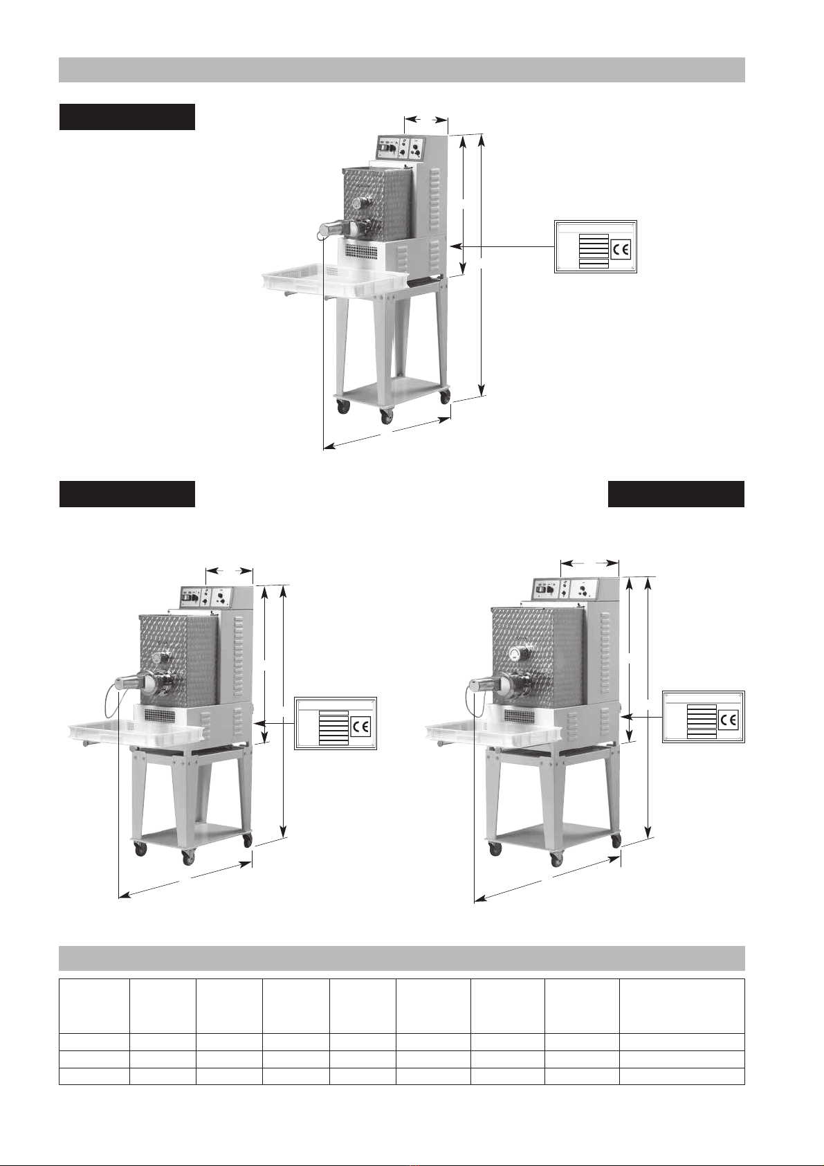
Model 3-phase standard power 1-phase optional power
230 50-60 Hz. 400 50-60 Hz. 415 50-60 Hz. 110 60 Hz. 230 50-60 Hz. 240 50 Hz.
TR 75/C YES YES YES YES YES YES
TR 95 YES YES YES /YES YES
TR 110 YES YES YES /YES YES
TRD 110 YES YES YES ///
TR 110 S YES YES YES ///
TRD 110 S YES YES YES ///
32
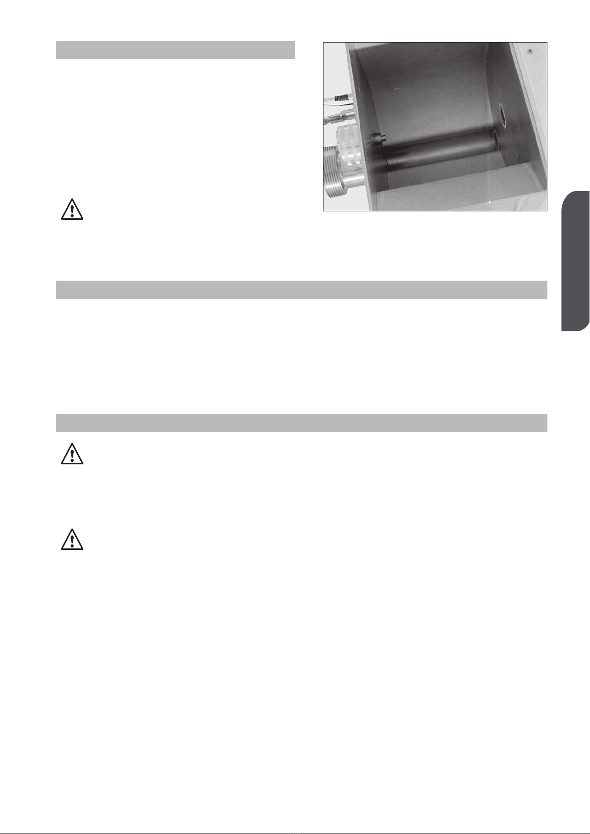
• The elements in contact with the noodles
are made of stainless steel or bronze for
foodstuffs.
• Moving parts mounted on ball bearings
with long-life sealing gaskets or with sup-
ports with greaser.
• Motor-powered; belt transmissions with
maintenance-free reduction gear and
mixer chain.
• Machine fitted with support toes with ela-
stic caps and, on request, trolley with four
wheels, 2 of which fitted with a brake and
machine corner retaining rims.
• Connection by flameproof power cable
according to the supply voltage required,
standard length L = 3 m, without terminal
plug.
• Accessories supplied:
- pasta-collecting frame
- metal ring blocking key
- liquid measuring jar.
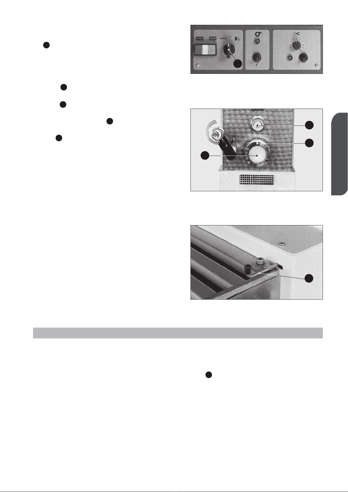
• Pasta cutting unit, fitted with a low voltage
operated motor and cutter.
• Fan for drying the pasta surface, to pre-
vent product from sticking.
• Working elements with the ability of turning
in two directions: this enables the knea-
ding of the initial dough, not yet ready,
without any damage to the drawing group.
• Iron parts are protected with stove-ena-
melled epoxy coating.
• Easy disassembling of the working parts;
the machine is freely accessible in order to
carry out thorough cleaning.
• The possibility of obtaining different pro-
ducts thanks to the change of the relevant
drawplate.
• Cooling unit with extrusion sleeve to ensu-
re an ideal temperature and control of
parts in contact with the product, from
model TR 95 to model TRD 110 S, on
request only on model TR 75.
• Mod. TRD 110 and TRD 110 S: Machine
with twin dough preparation tank for conti-
nuous production. Independent controls
and inspection of the second tank.
N DLES PR DUCING MACHINE
Produces different kinds of noodles and is basically made up of a
kneading part and an extrusion unit in order to cut the finished product
INSTRUCTIONS
The machine has been foreseen only for the preparation of cereal-based flour noodles
for noodle shops and catering facilities.
WARNING
For reasons of hygiene, health and warranty, it is strictly prohibited to use the
machine for the processing of substances other than foodstuffs. Any other uses
are contrary to the applications, as originally intended by the manufacturer, who shall
as a consequence, not be held liable for any damage to the machine itself or to other
objects, or for any injuries to persons that may arise thereof. In taking the risk of misu-
se, the user will be held responsible for any consequences.
Always keep children away from the machinery.
• Power:

33
ENGLISH
1. PREPARING THE MACHINE
Prepare the machine before every pro-
cess cycle.
BE SURE that the machine, especially
parts which come in contact with food
products (extrusion sleeve, Archimedean
screw, pool, mixer, drawplate and knife) are
perfectly clean (see chapter 6 CLEANING
on page 45).
Always clean with machine off.
Fig. 1
2. OPERATING PRINCIPLE
This machine kneads the different products desired and enables you to obtain different kinds
of noodles with a different group of lengths because it draws the dough, thanks to different
discs. This action is carried out thanks to a mixer linked to an Archimedean screw which obli-
ges the product to assume the desired shape going through a drawplate.
3. USE OF THE MACHINE
Only after making sure that the machine is completely clean, especially all the
parts which are directly in contact with the product (extrusion sleeve, Archimedean
screw, pool, mixer, drawplate, knife, lid, control system; if it is necessary, use some
warm water; see chapter 6 CLEANING page 45) you can carry out the requested ope-
rations in order to have the desired dough.
CAUTION: the machine will run only if the safety microswitch is serviceable and per-
fectly positioned.

34
CONTROL PANEL
5 3 6 9
4 2
10
8
CONTROL PANEL KEY
1 - Temperature reader only for TRD 110 S
2 - KNEAD÷DRAW selector
3 - Start button
4 - Start pilot lamp
5 - Stop push button
6 - Fan switch
7 - Fan pilot lamp
8 - Cutter switch
9 - Cutter operation pilot lamp
10 - Cutter speed variation control
11 - 2nd tank mixer control stop button
12 - 2nd tank mixer control start button
13 - 2nd tank mixer operating pilot light
16 -
Emergency stop button only for TRD and TRD S
TR 75 - TR 95
TR 110 - TR 110 S
Panel
7
4
1
7
10
16
12
13
35
2
11
6
9
8
TRD 110 S Panel
4
10
16
12
35
2
7
6
9
8
TRD 110 Panel
11
13

35
ENGLISH
After having turned the machine off:
• switch the selector to the “0” position (Fig.
2) and check the correct set-up of the
Archimedean screw, making sure that the
cylinder part is sustained by the dragging
shaft;
• then make sure that the plastic cap
(Fig. 3 ) which replaces the drawplate is
correctly positioned and the ring nut
(Fig. 3 ) is well-screwed on;
• finally block the mixer in its place, thanks to
the head-knob (Fig. 3 ).
Lift the tank lid by turning the coupling lever
(Fig. 4 ) and always put in the pre-establi-
shed ingredients in the following sequence:
flour and then, after closing the cap, all the
other liquid elements.
In order to obtain the right dough, you need
to create the precise ratio between the wei-
ght of the flour and the weight of the liquid
part; in order to obtain a very good product,
the flour has to contain a humidity percenta-
ge of no more than 15%; this allows the
addition of water equal to 33% or up to 35%
of the flour’s weight. If you are using flours
with different humidity contents, please
change the quantity of the liquid in the oppo-
site ratio. Moreover, in order to better use
the machine, the product inside the pool has
to be higher than at a minimum level which
coincides more or less with the position of
the mixer axle.
A
C
B
A
A
Fig. 2
Fig. 3
Fig. 4
A
A
B
C
Any kind of flour can be used (bran or bran-
flour). The dough can be kneaded only with
eggs or with a mix of water and eggs. Water
can be partially replaced by spinach or well-
cut vegetables in order to obtain green
noodles. Because the flour’s humidity chan-
ges according to the kind used, the environ-
ment and the place where it is stocked, the
quantities indicated have to be adapted to
the kind of flour which is used, lowering or
increasing the quantity of water. The dough
is the right one when, at the end of kneading
process, it is as big as coffee beans.
If the lumps form in the flour you have pou-
red in too much liquid.
In this case, before turning the switch
(Fig. 2 )FROM KNEAD TO DRAWPLATE
you will have to add some more flour and
knead a little longer. If the flour does not
form a ball and is too floury, add some more
water.
For the dough for the sheet of pasta which is
to be re-kneaded, use “00” flour and add two
eggs per kilo of flour (maximum). With these
quantities you will obtain a very stretchy
dough which is easy to knead.
A
3.1 USEFUL ADVICE IN ORDER TO OBTAIN A GOOD DOUGH
A

36
• Supposed weight of an egg: 50 grams.
• If you take 1 egg away you need to add 50 grams of water.
• To obtain a good dough: 1 kg of flour + 350 grams of humidity-liquid.
3.2 QUANTITIES IN ORDER TO OBTAIN A GOOD DOUGH
FLOUR-EGG MIXTURE FLOUR-EGG-WATER MIXTURE
Flour daN Egg No. Mixture daN Flour daN Egg No. Water l Mixture daN
1 7 1,35 1 4 0,15 1,35
2 14 2,70 2 8 0,30 2,70
3 21 4,05 3 12 0,45 4,05
4 28 5,40 4 16 0,60 5,40
5 35 6,75 5 20 0,75 6,75
6 42 8,10 6 24 0,90 8,10
7 49 9,45 7 28 1,05 9,45
8 56 10,80 8 32 1,20 10,80
9 63 12,15 9 36 1,35 12,15
10 70 13,50 10 40 1,50 13,50
Close the lid and put the selector on position . Press the start button.
Add the liquid part pouring it gradually but as quickly as possible through the small hole in
the lid. At the end of the kneading operation, which should take around 10 minutes, make
sure the product has the right thickness and should look like coffee beans (check through the
small holes of the lid).
Turn the machine off by switching the selector to “0”.
TR 75 - TR 95 - TR 110 - TR 110 S
Panel
TRD 110 S Panel TRD 110 Panel

37
ENGLISH
3.3 INSTALLATION OF THE DRAWPLATE
AND START-UP OF PRODUCTION
Make sure the machine is switched off.
Withdraw the filter (Fig. 5 ) and the draw-
plate (Fig. 5 ) requested from the contai-
ner filled with water where it was put after its
last use. Thoroughly rinse with plenty of run-
ning, warm water, in order to have the piece
at the right temperature (see chapter 6
CLEANING page 45).
Dry it with a soft cloth.
Unscrew the blocking ring nuts (Fig. 5 )
and carefully clean the internal part including
the edging.
Take the plastic cap off (Fig. 5 ).
Set up the filter and the drawplate while
taking good care of the Archimedean screw
(Fig. 5 ) at the center of the disk.
Close the metal ring with the help of the
wrench supplied (Fig. 6 ) and check that
the various parts are in place and are not
shifted axially because dough has added
thickness (Fig. 5 - point ).
In order to start production, position the
selector (Fig. 7 ) on the position and
press the start button (Fig. 7 ).
The initial product coming out of the machine
has an unacceptable appearance; this is the
reason why it has to be eliminated.
After a short time (a couple of minutes) the
product coming out is acceptable, the colour
goes from whitish to yellow and it has a
greater consistency.
In order to cut the pasta to the desired length
it is necessary to set up the cutting device
(Fig. 6 ), made up of motor and knife, cho-
sen from those available.
Set up the unit for this, by simply fitting the
cutter (Fig. 8 ) on the drive shaft in the
standby position. Placing the cutting unit
opposite the drawplate, taking care that the
cutter moves axially towards the motor and
is fits neatly with the drawplate.
To complete this operation, facilitate the
movement of the knife by helping yourself,
with your hands, closing the knife tang
between two fingers (Fig. 8).
Regulate the knife speed according to the
A
B
C
A
1
A
E
D
C
B
A
Fig. 5
E
C
B
A
D
Fig. 6
A
B
Fig. 7
C
A
B
Fig. 8
1
A
D

38
desired pasta length, by turning the speed-
control knob (Fig. 7 ).
If the product is quite wet and tends to be
sticky, it is best to dry the surface in any
case, by switching on the fan (Fig. 7 ).
The product may be collected on the frame
supplied (Fig. 9 ), leaning on retractable
rods (Fig. 9 ) supplied with the machine.
For machines fitted with an extrusion
sleeve cooling unit, switch on the system
taking account of a few operating parame-
ters of the dough and room temperature.
At any rate, with average dough, after 3 - 5
minutes, check the external temperature of
the ring nut and if it seems too high, gradual-
ly open the regulating valve.
Frequently check the temperature and regu-
late water flow, tending to keep temperature
constant.
NOTE: If the product is kneaded at an
excessive temperature, it tends to
change colour and/or blanch slightly.
3.4 VARIANT FOR MOD. TRD 110 S
Model TRD 110 S (Fig. 10) is fitted with a
temperature setting and control display (Fig.
10 ): when the machine is turned on, the
display button flashes for a few seconds
and, therefore, shows the momentary tem-
perature on the extrusion sleeve. To see the
last temperature selected, press button
“SET” once (Fig. 11 ).
If you want to vary the sleeve control tem-
perature, press the button “SET” and at the
same time button “UP” or “DOWN”
(Fig. 11 ) depending on whether you want
to increase or decrease the controlled tem-
perature, until you see the desired tempera-
ture appear on the display unit.
Release the pressed button; the system
memorizes the new temperature, even if
the machine is turned off. After a few
seconds, the temperature shown on the
sleeve will appear on the display unit.
B
A
A
B
A
D
B
Fig. 9
Fig. 12
Fig. 11
Fig. 10
A
B
A
B
Mod. TR 110 S
A
A

39
ENGLISH
3.5
VARIANT FOR MOD. TRD 110
The TRD 110 model uses the second tank
(Fig. 13 ) to enable dough to be kneaded
(press button - Fig. 12) simultaneously
with the worm screw extrusion stage. This
allows output to be increased considerably.
Make the dough as shown for the main tank
then tip it into the main tank while rotating it
manually. To carry out this operation release
the knob (Fig. 31) and rotate the tank by
means of the lever (Fig. 31 ), to obtain
continuous cycle production.
After the operation:
• stop the machine by switching the selector
(Fig. 15 ) as well as the others to the “0”
position;
• rotate the cutting group to the stop position
(Fig. 16);
• turn the selector (Fig. 15 ) to the knead
position for 10-15 seconds in order to
eliminate the pressure on the die caused
by the product ;
• return the switch to “0”;
• disassemble and wash the movable parts
(Fig. 17 - 18) and clean the machine (see
Unit 6 CLEANING page 45);
• close the water tap, for machines fitted with
a cooled extrusion sleeve.
D
C
B
A
A
B
Fig. 13
B
Fig. 15
A
Fig. 16
Fig. 17
Fig. 18

40
4. TRANSPORTATION AND HANDLING
The machine is placed on a pallet and ship-
ped enclosed in special package (Fig. 19)
fastened to the wooden pallet with straps.
Besides the machine, the package includes:
a disassembled trolley, when requested, with
machine support wheels, operating instruc-
tions and a declaration of compliance with
the EU directive. The accessories supplied
and cutting unit are placed inside the dough
preparation tank (Fig. 20), adequately
packaged and protected.
When unloading the machine from the tran-
sport vehicle, lift at the points marked on the
packaging using suitable equipment.
Unless you need to check the contents, you
are recommended not to open the packaging
until the moment of installation.
Remove straps, packing and polystyrene
strips.
Dispose of this material according to the
regulations in force. Lift the machine and
place on the installation site.
Remove the supporting pallet using straps of
suitable carrying capacity (approx. 6 times
the weight of the machine).
These will have to be positioned near the
feet as indicated in Fig. 21.
The whole operation is to be controlled by
adequate manual or power-driven lifting
equipment.
Machine fitted with a trolley and wheels
Assemble the trolley, tightening right down
the leg screws (Fig. 22 ) and the wheels
nuts (Fig. 22 ).
Then lift the machine about 20-25 mm.
above the height of the trolley, ensuring that
the clamped wheels (Fig. 22 ) are in the
front of the machine.
Then lower machine until it rests on trolley,
perfectly retained by leg corners.
The machine must be lifted and pla-
ced on the trolley by two persons.
Make sure that the trolley support level is
horizontal and compact.
The machine must be moved horizontally
by carefully pushing the unit from the
C
B
A
Fig. 22
AA
B
Fig. 19
Fig. 20
Fig. 21
Mod. TR 75÷95÷110
C

Fig. 24
41
ENGLISH
front or rear of the machine and not
sideways. Make sure that along the plan-
ned route there are no objects hindering
regular wheel rotation.
If these precautions are not followed, the
machine may be overturned.
4.1 VARIATION FOR MODELS TR 110 S,
TRD 110 AND TRD 110S
The machine shipped on a pallet in wooden
box (Fig. 23), including accessories and a
declaration of compliance.
Unpack the machine in its workplace, lift it
with the belts (Fig. 24) and remove the woo-
den pallet. Position the model TRD 110 (Fig.
25) on the previously-mounted trolley.
Push the trolley to the planned position,
taking the precaution to handle it carefully
since its top-heavy weight may make the
machine unstable when being moved.
Make sure there are no objects hindering
regular wheel rotation.
Fig. 25
Mod. TR 110 S - TRD 110 S
Mod. TRD 110
Fig. 23
Mod. TR 110 S - TRD 110 S

42
5. INSTALLATION, CONNECTION
AND SET-UP
Install and use the machine in a room that
can be efficiently ventilated, and where the
floor is smooth and compact and easy to
clean.
WARNING: While the machine is
operating, in order to obtain a product
with the right thickness and humidity,
avoid air currents which will cause pre-
cocious drying of the product together
with its deterioration.
To ensure the necessary stability of the
machine, check that the wheels rest firmly
on the floor, otherwise move the machine sli-
ghtly until the four wheels have been steadily
laid on the ground. Lastly, clamp the wheel
with the brake (Fig. 26 ).
Position the machine in the desired place
with a free back space of around 50 centi-
meters and a side space of 70-80 centime-
ters (Fig. 27) in order to guarantee easy use
of the machine and its cleaning.
For machines fitted with a trolley, make
sure that the brake provided is clamped by
pulling the lever down (Fig. 26 ).
Check that the voltage of the machine which
is written on the identification label, (Fig. 28)
matches the one foreseen by the system on
your premises.
Attach the right plug to the machine power
cable in order to make the electrical connec-
tion to the system.
WARNING:
Have
the plug fitted
to
the power supply
by qualified person-
nel. Take the necessary precautions to
prevent the cable from being crimped
or damaged.
5.1 CUTTING UNIT ASSEMBLY
Remove the components in the tank.
Assemble the cutting unit, after removing
B
A
Fig. 26
B
A
50
cm
Fig. 27
70÷80
cm
MODELLO
N°DI SERIE
ANNO
VOLT
Hz
Kw
PESO
MADE IN ITALY
70÷80
cm

43
ENGLISH
the socket-head screw (Fig. 29 ) from the
bearing. Then tighten the screws right down
again (Fig. 29).
Plug the unit into the power supply socket
(Fig. 29 ) of the machine; let the safety
coupling click in.
5.2 CONNECTION TO THE WATER SYSTEM
For machines supplied with an extrusion
sleeve cooling system, connect the machi-
ne to the water system, install the sending
tube, (when it is non-existant: use a tap, pos-
sibly with screw-control) to the outer part of
the machine, in order to regulate the water
flow. The exit-flow tube must allow free water
discharge. We recommend that the water
pressure inside the machine, does not
exceed the 1.0 - 1.5 bar.
To connect the external parts, use a flexible
tube with an inside diameter of 13 mm,
safely fixed by a metal band with a screw
that can be closed with a screw-driver or key
(Fig. 30).
5.3
VARIANT FOR MOD. TRD 110 S
The TRD 110 S model uses the second tank
(Fig. 31 ) to enable dough to be kneaded
(press button - Fig. 31) simultaneously
with the worm screw extrusion stage. This
allows output to be increased considerably.
Make the dough as shown for the main tank
then tip it into the main tank while rotating it
manually. To carry out this operation release
the knob (Fig. 31) and rotate the tank by
means of the lever (Fig. 31 ), to obtain
continuous cycle production.
D
C
B
A
B
A
Fig. 30
Fig. 31
Fig. 29
A
B
A
C
D
B

44
5.4 CONTROL OF THE INSTALLATION
N.B.: Every operation is voluntarily com-
manded by means of the start but-
ton with the tank safety lid closed
by means of the double safety devi-
ce.
Turn the selector to the knead position
(Fig. 32 ) and check:
• Make sure that the mixer is rotating coun-
ter-clockwise, facing the front of the machi-
ne, when the switch (Fig. 32 ) is placed
on the “mix” position , (the Archime-
dean screw also turns counter-clockwise).
In the “0” position all of the machine’s ele-
ments should be still; in the drawplate posi-
tion , the mixer turns clockwise, the
Archimedean screw should turn the same
way (check from the lid slits).
• Check the efficiency of the double safety
device on the lid. The device sets off two
micro-switches; one is controlled by the lid
hook (Fig. 33 ), inside the stop slot; and
the other from the lid itself.
To check this, make sure that microswitch
in the slot begins to be enabled when the
hook has not yet gone out of the slot itself.
The lid microswitch must be heard to click
when the lid is lifted approx. 10 - 15 mm.
(Fig. 33).
• Operation of the buttons and pilot lamps
according to the signs given (Fig. 32).
• The knife in its working position should be
turning clockwise.
• The correct connection of the water cooling
system, should include checking for even-
tual water leaks.
If the machine or some of its parts
breakdown, call your local authorised
dealer or concessionaire for repairs.
A
A
A
Fig. 32
Fig. 33
10-15
mm
A
A

45
ENGLISH
6. CLEANING
Warning: For healthy and
hygienic processing of food
products, be sure to keep your
machine and the surrounding
environment clean.
DANGER: Always cut off the power
supply before cleaning.
You have to properly clean all the elements
which are in contact with the product
(Fig. 34 - 35) protection lid, pool, mixer,
Archimedean screw, drawplate, filter, ring nut
and knife, when the product is still soft.
The moving parts have to be disassembled
as follows:
• Mixer: make sure the external shovel
(Fig. 35 ) is in the upper vertical position
(only this position allows the disassembling
of the piece) (Fig. 35).
Disassemble the mixer by unscrewing the
external movable support (Fig. 35 ) until
releasing the mixer; unthread the shaft
from its place and at the same time, rotate
the external pin towards the top.
If you want to assemble the piece follow
these instructions vice versa. Line the cen-
tral point of the shaft with the peg of the
moving support; thereafter, screw the sup-
port, but without blocking it.
• Metal ring, drawplate and filter: unscrew
the metal ring with the appropriate wrench
(Fig. 36 ) being careful not to let any pie-
ces fall, since the metal ring is moved from
its place, the product and parts still weigh a
few kilos and can easily slip from your
hands, causing damage both to people or
to the pieces themselves.
• Archimedean screw: after disassembling
the ring nut, the drawplate (Fig. 36 ) and
the filter, the Archimedean screw can
easily be taken off the machine by pushing
its spiral from the internal end.
B
A
B
A
Fig. 34
Fig. 35
Fig. 36
A
A
B
B
This manual suits for next models
5
Table of contents