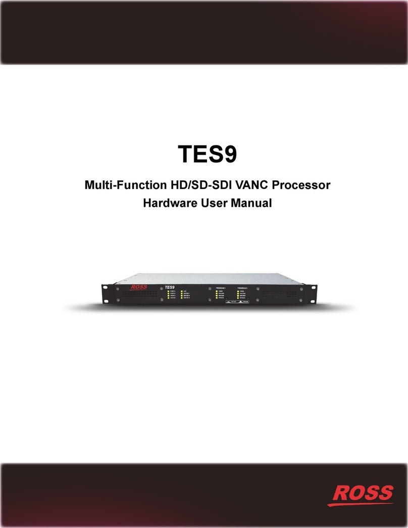
Ross TES9 User manual

TES9
Multi-Function HD/SD-SDI VANC Processor
Software User Manual

Thank you for choosing Ross
You've made a great choice. We expect you will be very happy with your purchase of Ross Technology.
Our mission is to:
1. Provide a Superior Customer Experience
• offer the best product quality and support
2. Make Cool Practical Technology
• develop great products that customers love
Ross has become well known for the Ross Video Code of Ethics. It guides our interactions and
empowers our employees. I hope you enjoy reading it below.
If anything at all with your Ross experience does not live up to your expectations be sure to reach out to
David Ross
CEO, Ross Video
Ross Video Code of Ethics
Any company is the sum total of the people that make things happen. At Ross, our employees are a
special group. Our employees truly care about doing a great job and delivering a high quality customer
experience every day. This code of ethics hangs on the wall of all Ross Video locations to guide our
behavior:
1. We will always act in our customers’ best interest.
2. We will do our best to understand our customers’ requirements.
3. We will not ship crap.
4. We will be great to work with.
5. We will do something extra for our customers, as an apology, when something big goes wrong and
it's our fault.
6. We will keep our promises.
7. We will treat the competition with respect.
8. We will cooperate with and help other friendly companies.
9. We will go above and beyond in times of crisis. If there's no one to authorize the required action in
times of company or customer crisis - do what you know in your heart is right. (You may rent
helicopters if necessary.)

TES9 Software User Manual
• Ross Part Number: TES9DR-004B-04
• Release Date: January 27, 2015.
Copyright
© 2015 Ross Video Limited. Ross®, openGear®, and any related marks are trademarks or
registered trademarks of Ross Video Ltd. All other trademarks are the property of their respective
companies. PATENTS ISSUED and PENDING. All rights reserved. No part of this publication
may be reproduced, stored in a retrieval system, or transmitted in any form or by any means,
mechanical, photocopying, recording or otherwise, without the prior written permission of Ross
Video. While every precaution has been taken in the preparation of this document, Ross Video
assumes no responsibility for errors or omissions. Neither is any liability assumed for damages
resulting from the use of the information contained herein.
Patents
Patent numbers US 7,034,886; US 7,508,455; US 7,602,446; US 7,802,802 B2; US 7,834,886;
US 7,914,332; US 8,307,284; US 8,407,374 B2; US 8,499,019 B2; US 8,519,949 B2; US
8,743,292 B2; GB 2,419,119 B; GB 2,447,380 B; and other patents pending.

Environmental Information
The equipment that you purchased required the extraction and use of natural
resources for its production. It may contain hazardous substances that could
impact health and the environment.
To avoid the potential release of those substances into the environment and to diminish the need
for the extraction of natural resources, Ross Video encourages you to use the appropriate
take-back systems. These systems will reuse or recycle most of the materials from your
end-of-life equipment in an environmentally friendly and health conscious manner.
The crossed out wheelie bin symbol invites you to use these systems.
If you need more information on the collection, reuse, and recycling systems, please contact your
local or regional waste administration.
You can also contact Ross Video for more information on the environmental performance of our
products.

Company Address
Ross Video Limited Ross Video Incorporated
8 John Street P.O. Box 880
Iroquois, Ontario, K0E 1K0 Ogdensburg, New York
Canada USA 13669-0880
General Business Office: (+1) 613 • 652 • 4886
Fax: (+1) 613 • 652 • 4425
Technical Support: (+1) 613 • 652 • 4886
After Hours Emergency: (+1) 613 • 349 • 0006
E-mail (General Information): solutions@rossvideo.com
Website: http://www.rossvideo.com


TES9 Software User Manual (Iss. 04) Contents • i
Contents
Introduction 1
Data Distribution Overview................................................................................................. 1-2
Video Source ......................................................................................................... 1-3
Transmit Computer................................................................................................ 1-3
How to Use this Manual ...................................................................................................... 1-5
Installation 2
Installation ........................................................................................................................... 2-2
TES9 as an Encoder............................................................................................... 2-2
TES9 as a Receiver................................................................................................ 2-2
Encoder Configuration 3
Installing the Setup Software............................................................................................... 3-2
Configuring the Encoder for Setup Mode............................................................................ 3-3
Starting TES9Set.................................................................................................................. 3-4
To start TES9Set ................................................................................................... 3-4
Types of Connections ............................................................................................ 3-4
Main TES9Set Menu ........................................................................................................... 3-6
ID Area .................................................................................................................. 3-6
TCP/IP Area .......................................................................................................... 3-6
Program 1/Program 2 Tabs.................................................................................... 3-7
General Config Area.............................................................................................. 3-7
Line Usage Button................................................................................................. 3-8
Stream Setup Area................................................................................................. 3-9
Save and Exit Button............................................................................................. 3-9
Cancel Button ........................................................................................................ 3-9
Load Factory Defaults Button ............................................................................... 3-9
Transparent Module 4
Overview.............................................................................................................................. 4-2
Features................................................................................................................................ 4-3
Data Type .............................................................................................................. 4-3
Port Selection ........................................................................................................ 4-4
Send Field Indicator .............................................................................................. 4-4
Data Direction ....................................................................................................... 4-4
Line Selection........................................................................................................ 4-4
Settings .................................................................................................................. 4-4
Byte Mode ............................................................................................................. 4-5
Packet Mode Priority............................................................................................. 4-6
Data Throughput Calculations ............................................................................................. 4-8
Captioning Module 5
Overview.............................................................................................................................. 5-2
Features................................................................................................................................ 5-3

ii • Contents TES9 Software User Manual (Iss. 04)
Data IDs ................................................................................................................. 5-3
Line Selection ........................................................................................................ 5-3
Caption Service Information Defaults ................................................................... 5-3
Port Settings ......................................................................................................................... 5-4
Primary Captioning Port Tab................................................................................. 5-4
Secondary Captioning Port Tab............................................................................. 5-6
XDS Port Tab ........................................................................................................ 5-6
708 Output Port Tab .............................................................................................. 5-7
608 Output Port Tab .............................................................................................. 5-7
Redistribution Control (Broadcast Flag).............................................................................. 5-8
Constant Data Module 6
Configuration ....................................................................................................................... 6-2
Bridging Module 7
Overview .............................................................................................................................. 7-2
Troubleshooting 8
Troubleshooting Questions .................................................................................................. 8-2
STATUS 1-3 LEDs .............................................................................................................. 8-4
Appendix A. Software Interface for LAN 9
Overview .............................................................................................................................. 9-2
Example................................................................................................................................ 9-3
Appendix B. Captioning Commands 10
The Command Set.............................................................................................................. 10-2
Reset Encoder ...................................................................................................... 10-4
Enter Realtime Mode ........................................................................................... 10-4
Enter Pass-Through Mode ................................................................................... 10-5
Set Null Mode......................................................................................................10-5
Set Transparent Mode.......................................................................................... 10-6
Turn Off Channels ............................................................................................... 10-6
Turn On Channels................................................................................................ 10-6
Start Encoding Text Data..................................................................................... 10-6
Stop Encoding Text Data..................................................................................... 10-7
Start Encoding XDS Data (Interval Packets)....................................................... 10-7
Start Encoding XDS Data (Fill Packets) ............................................................. 10-8
Stop Encoding XDS Data .................................................................................... 10-9
Specify Upstream Packet Priority........................................................................ 10-9
Store and Forward Upstream Packets.................................................................. 10-9
Start Encoding Program Descriptor..................................................................... 10-9
Stop Encoding Program Descriptor ................................................................... 10-10
Service Information Enquiry ............................................................................. 10-11
Set Operating States........................................................................................... 10-12
Set Baud Rate .................................................................................................... 10-12
Vendor and Version Enquiry ............................................................................. 10-12

TES9 Software User Manual (Iss. 04) Introduction • 1–1
Introduction
In This Chapter
This chapter contains the following sections:
• Data Distribution Overview
• How to Use this Manual
A Word of Thanks
Congratulations on choosing a TES9 Multi-function HD/SD-SDI VANC Processor. Your TES9 is
part of the Ross family of products, backed by Ross Video’s experience in engineering and design
expertise since 1974.
You will be pleased at how easily your new TES9 fits into your overall working environment.
Equally pleasing is the product quality, reliability and functionality. Thank you for joining the
group of worldwide satisfied Ross Video customers!
Should you have a question pertaining to the installation or operation of your TES9, please
contact us at the numbers listed on the back cover of this manual. Our technical support staff is
always available for consultation, training, or service.

1–2 • Introduction TES9 Software User Manual (Iss. 04)
Data Distribution Overview
The TES9 is part of a system that allows data to be inserted into the VANC (Vertical Ancillary)
area of one or two SMPTE 292M or 259M video signals for distribution over a video network.
This method of data embedding ensures that the data follows the video signal wherever it is
routed. Eventually, the video signal reaches a location where the data is extracted and processed.
The TES9 family is comprised of two models. One model supports a single video stream. The
other model supports two video streams.
The TES9 can be used to add the data to the digital video stream, or extract it, or both. Figure 1.1
shows the flow of video and data through the TES9. This shows that each channel is equipped
with a VANC/VBI decoder that provides extracted data to the CPU, and a VANC/VBI encoder
that accepts data from the CPU for insertion into the video. The CPU also has access to a variety
of standard data ports: RS-232, LAN and modem.
These facilities allow the TES9 to perform a number of functions:
• Inserting data received from one or more of the data ports into the video. This is normally
called “encoding”, “inserting” or “embedding”.
• Extracting data from the video and forwarding it to one or more data ports. This is
normally called “decoding”, “extracting” or “disembedding”.
• Inserting data extracted from one video signal into the other. This is called “bridging”.
It should be noted that the TES9 is designed to be primarily a VANC encoder/decoder. For this
reason, its use of VBI data is limited the Bridging module, which allows WST data from a
SMPTE 259 video signal to be bridged to VANC data in a SMPTE 292 video signal, or vice
versa.
Figure 1.1 Simplified Dataflow Diagram
Figure 1.2 shows the pieces of equipment involved in a simple data distribution system. Each of
the pieces in this system is described briefly in the following sections. For clarity, only one video
signal and one data stream are used in this example.
Note — On some models of TES9, the two video channels may be labeled “PROGRAM”
and “AUXILIARY”, instead of “PROGRAM 1" and “PROGRAM 2", respectively. Their
functions are nevertheless identical.
PGM 1
IN DESERIALIZE
DESERIALIZE
PGM 2
IN
CPU
Video
Data
Legend
10/100
base-T LAN
MODEM
RS-232
VANC/VBI
DECODE
VANC/VBI
DECODE
PGM 1
OUT
SERIALIZE
VANC/VBI
ENCODE
PGM 2
OUT
SERIALIZE
VANC/VBI
ENCODE

TES9 Software User Manual (Iss. 04) Introduction • 1–3
Figure 1.2 Workflow Diagram — Simple Data Distribution System
Video Source
The video source provides the serial digital video signal into which the TES9 encoder inserts the
VANC data. The video signal may be any of those listed in Table 1.1.
Transmit Computer
The transmit computer executes application programs that
• configure the encoder; and/or
• supply data to the encoder
TES9Set, the application program used to configure the TES9, is supplied with the TES9. This is
for use on computers with Microsoft® Windows 98® operating system or later.
Data is sent to the encoder by application programs which may be written specifically for the data
distribution system (e.g. a closed captioning server), or may be a generalized source of a serial
data stream.
Table 1.1 Supported Video Formats
Type Format Defining Standards
259M
525 lines, 59.94 Hz ITU-R BT.601, SMPTE 125M
625 lines, 50 Hz ITU-R BT.601
292M
1080i, 50 Hz SMPTE 274M
1080i, 59.94 Hz SMPTE 274M
1080i, 60 Hz SMPTE 274M
1080p, 23.98 Hz SMPTE 274M
1080p, 24 Hz SMPTE 274M
1080sf, 23.98 Hz SMPTE 274M, RP211
1080sf, 24 Hz SMPTE 274M, RP211
720p, 50 Hz SMPTE 296M
720p, 59.94 Hz SMPTE 296M
720p, 60 Hz SMPTE 296M
VIDEO
SOURCE
TRANSMIT
COMPUTER
RECEIVE
COMPUTER
TES9
ENCODER
TES9
RECEIVER
Broadcast
Network
Video
Legend
RS-232, LAN, or MODEM
RS-232, or LAN

1–4 • Introduction TES9 Software User Manual (Iss. 04)
Transmit Computer to TES9 ENCODER LINK
The link between the transmit computer and encoder is a combination of LAN and serial
connections.
The LAN system is Ethernet 100baseT using TCP/IP, with up to eight data connections.
In addition to the eight possible LAN connections, there can be up to 4 serial feeds connected to
the encoder. Three of these are RS-232 operating at speeds up to 115,200 baud. The fourth serial
feed is a 33.6K bps modem connection.
TES9 ENCODER
The TES9 can be loaded with up to a total of sixteen software modules. It can encode up to eight
different input data streams into VANC lines of each PROGRAM 1 and PROGRAM 2 video
signals. The software modules in the encoder determine the format of VANC data that is inserted.
The software modules currently available for the encoder, and described in this manual, are:
• Transparent
• Closed Captioning (with optional Redistribution Control feature)
• Constant Data
• OP-47 Bridge
TES9 RECEIVER
The TES9 receiver is identical to the TES9 encoder, but has been configured by the user (with
TES9Set) to operate as a receiver. In this mode, it extracts the data from the VANC data area of
the SMPTE 292M signal, and sends it to the receive computer via LAN and serial connections.
TES9 RECEIVER to RECEIVE Computer Link
The link between the TES9 receiver and the receive computer can be any combination of LAN
and serial connections, as discussed above for the Transmit Computer to TES9 Encoder link.
RECEIVE Computer
The receive computer processes the extracted VANC data. The program that processes the data
can be either a Ross Video application program or a user-provided program. The term “computer”
is used here to represent any type of device that can accept data from the TES9; for example, in
the case of captioning data, this might be an MPEG video encoder.
Note — In this section of the manual, the term 'encoder' is used to refer to a TES9 which
is being used to insert data into the video signal, and 'receiver' is used to refer to a TES9
which is extracting data from the video signal. In general, however, the TES9 is often
referred to as an encoder, regardless of its current function; it can, in fact, be used to insert
and receive data simultaneously

TES9 Software User Manual (Iss. 04) Introduction • 1–5
How to Use this Manual
The following is a brief description of the contents of each chapter in this manual:
• Chapter 1— Introduction
• Chapter 2 — Describes the installation of the TES9.
• Chapter 3 — Describes the part of the configuration program that applies to all types of
modules.
• Chapter 4 — Describes the Transparent module.
• Chapter 5 — Describes the Captioning module.
• Chapter 6 — Describes the Constant Data module.
• Chapter 7 — Describes the Bridging module.
• Chapter 8 — Gives troubleshooting procedures for various situations.
• Appendix A — Describes the interface between the transmit computer software and the
LAN encoder.
• Appendix B — Describes the captioning command set.
You should read chapters 1 to 3 and the chapters for the software modules that you have installed
in your encoder. Consult Chapter 8 if you are having problems using your TES9.

1–6 • Introduction TES9 Software User Manual (Iss. 04)

2–2 • Installation TES9 Software User Manual (Iss. 04)
Installation
The procedure for installing the TES9 is as follows:
1. Install and connect the TES9 chassis, following the procedure described in the TES9
Hardware Manual.
2. It is advisable to make all your connections to the TES9 rear panel with the power off.
3. Once you have made all necessary connections, you can turn the power on.
TES9 as an Encoder
If you plan to use the TES9 as an encoder, proceed as follows:
1. Connect the equipment providing the video signal source to the PROGRAM 1 IN
connector on the encoder.
2. Connect the PROGRAM 1 OUT connector on the encoder to the equipment that is to
receive the video signal with the inserted VANC data.
3. If using a serial data connection, connect the transmit computer(s) to the serial port(s) on
the encoder using a null modem cable (a null modem cable is shipped with the encoder).
Alternatively, connect the transmit computer to the LAN connector on the encoder via
an Ethernet LAN, using a standard RJ45 cable.
TES9 as a Receiver
When using the TES9 as a receiver, proceed as follows:
1. Connect the equipment providing the video signal containing the VANC data to be
received to the PROGRAM 1 IN connector on the encoder.
2. Connect the TES9's PROGRAM 1 OUT connector to other equipment that needs this
video signal; if there is none, connect a 75 ohm termination to PROGRAM 1 OUT.
3. If using a serial data connection, connect the receive computer(s) to the serial port(s) on
the encoder using the supplied null modem cable. Alternatively, connect the receive
computer to the LAN connector on the encoder via an Ethernet LAN, using a standard
RJ45 cable.
4. If your TES9 is equipped with a second program video channel and you plan to use it,
follow the procedure described above for the Program 1 channel, connecting to
PROGRAM 2 IN and OUT instead of PROGRAM 1 IN and OUT.
Note — For proper operation, it is essential that the output be terminated in 75ohms.

TES9 Software User Manual (Iss. 04) Encoder Configuration • 3–1
Encoder Configuration
In This Chapter
A computer running Microsoft® Windows 98® operating system or later is required in order to
execute the TES9Set configuration program. As discussed previously, the computer and the
encoder can be connected locally via RS-232, or remotely using the modem or LAN port.
For an RS-232 connection, connect the supplied null modem cable from the encoder's Port A jack
to a COM port on the setup computer. Note that this can be the “transmit computer” connected in
Chapter 2.
The following topics are discussed:
• Installing the Setup Software
• Configuring the Encoder for Setup Mode
• Starting TES9Set
• Main TES9Set Menu

3–2 • Encoder Configuration TES9 Software User Manual (Iss. 04)
Installing the Setup Software
The configuration program, TES9Set, is supplied with the TES9 on a CD-ROM.
To install TES9Set on the computer's hard drive
1. Place the TES9Set disk in the CDROM drive.
2. If the setup program does not start automatically:
•GototheStart menu in and select Computer.
• Double-click the Compact Disk drive you inserted theTES9Set disk into.
• Double-click Autorun.EXE.
3. Click Install TES9Setup Software and follow the on-screen instructions.
Configuring the Encoder
There are three steps involved in configuring the encoder:
1. Connect the computer to the encoder through Port A or the modem or LAN jack. Refer
to the TES9 Hardware Manual for details.
2. Put the encoder into Setup mode (this is not necessary for the LAN encoder if its IP
address has already been set up). Refer to the section “Configuring the Encoder for
Setup Mode” on page 3-3 for details.
3. Run TES9Set as outlined the section “Starting TES9Set” on page 3-4.

TES9 Software User Manual (Iss. 04) Encoder Configuration • 3–3
Configuring the Encoder for Setup Mode
Whenever the TES9’s power is turned on, it begins operation using parameters stored in its
configuration memory. In order to change these operating parameters via Port A or the modem,
the TES9 must be placed in setup mode. All data sources should stop sending data to the encoder
before running TES9Set.
To select Setup mode
1. Ensure that the TES9 has completed its power-up sequence and is operational.
2. Press and hold the LOAD switch located on the TES9's rear panel for at least two
seconds. Refer to the TES9 Hardware Manual for switch location.
3. When the STATUS 1 LED begins alternating between green and yellow, the TES9 is
ready to be configured, and waiting for TES9Set to communicate with it using one of its
ports (Port A, modem or LAN).
4. The TES9 will leave Setup mode when you exit from TES9Set or you turn the TES9's
power off and on again.
To use setup via the LAN
1. You need to initially set the encoder's IP address through Port A or the modem, using
the above procedure.
2. After this initial setup, the TES9's configuration can be changed via the LAN connection
at any time, without pressing the LOAD switch to select Setup mode.

3–4 • Encoder Configuration TES9 Software User Manual (Iss. 04)
Starting TES9Set
This section outlines how to start the TES9Set program and the possible types of connections to
use.
To start TES9Set
1. Select the TES9Set menu entry from the Start > Programs menu.
2. Select the type of connection you wish to use from the Connection Method menu.
Connection Method Menu — Serial Connection Selected
Types of Connections
This section outlines the connection types available in the Connection Method menu.
Serial Port Connection
After selecting Serial as the method of connection, the COM port can be selected from the pull
down list. Click OK to proceed with the connection.
Modem Connection
Selecting the Modem as the configuration method allows the COM port and phone number to be
entered. Clicking the Properties button displays the following dialog.
Modem Settings Menu
Modem Settings allows you to select values which will work with your modem. The default
settings will work with many of the modern modems. If the defaults do not work then it is
recommended that you try changing the Modem Initialization first. There are five choices,
Modem1 through Modem4 and Custom. Selecting Modem1 through Modem4 will allow you to
try a different modem initialization string. If you have the exact initialization string required by
your modem, you can specify it by selecting Custom. The Dialing Prefix should not need to be
changed. Clicking Reset Defaults will restore the modem settings to the recommended defaults.
Other manuals for TES9
1
Table of contents
Other Ross Computer Hardware manuals
Popular Computer Hardware manuals by other brands

ADLINK Technology
ADLINK Technology aTCA-9710 user manual

Ista
Ista AMF2.0 Operator's manual

EK-Quantum
EK-Quantum Vector2 Strix RTX 3080 D-RGB manual

Alphacool
Alphacool Eisblock Aurora Acryl RTX 4080 AMP Trinity quick start guide

Freescale Semiconductor
Freescale Semiconductor e200z3 Reference manual

Shuttle
Shuttle MS52PN user manual