Rossato IRIS SLIM / IN Reference manual

IRIS SLIM / IN
Manual of installation and use
Rev. 1.1
ENGLISH

Copyright © January 2020 Rossato Group Srl
Dear customer, thank you for your attention to Rossato products.
All rights relating to this document are reserved by the Rossato Group and reproduction, even partial, is only possible with the authorisation of
the company. Rossato Group reserves the right to make any changes necessary to improve the product or document at any time, without prior
notice.
Translation in English of original in Italian language.

Table of contents
1.
Introduction ................................................................................................................................................. 4
1.1. General information .......................................................................................................................... 4
1.1.1. Description of symbols .......................................................................................................... 4
1.1.2. General information................................................................................................................. 4
2.
Unit description ............................................................................................................................................. 6
2.1. Destination of use .............................................................................................................................. 6
2.2. Unintended use ................................................................................................................................. 6
2.3. Identification plate ............................................................................................................................. 6
2.4. Technical features ............................................................................................................................. 7
2.5. Operating limits ................................................................................................................................. 8
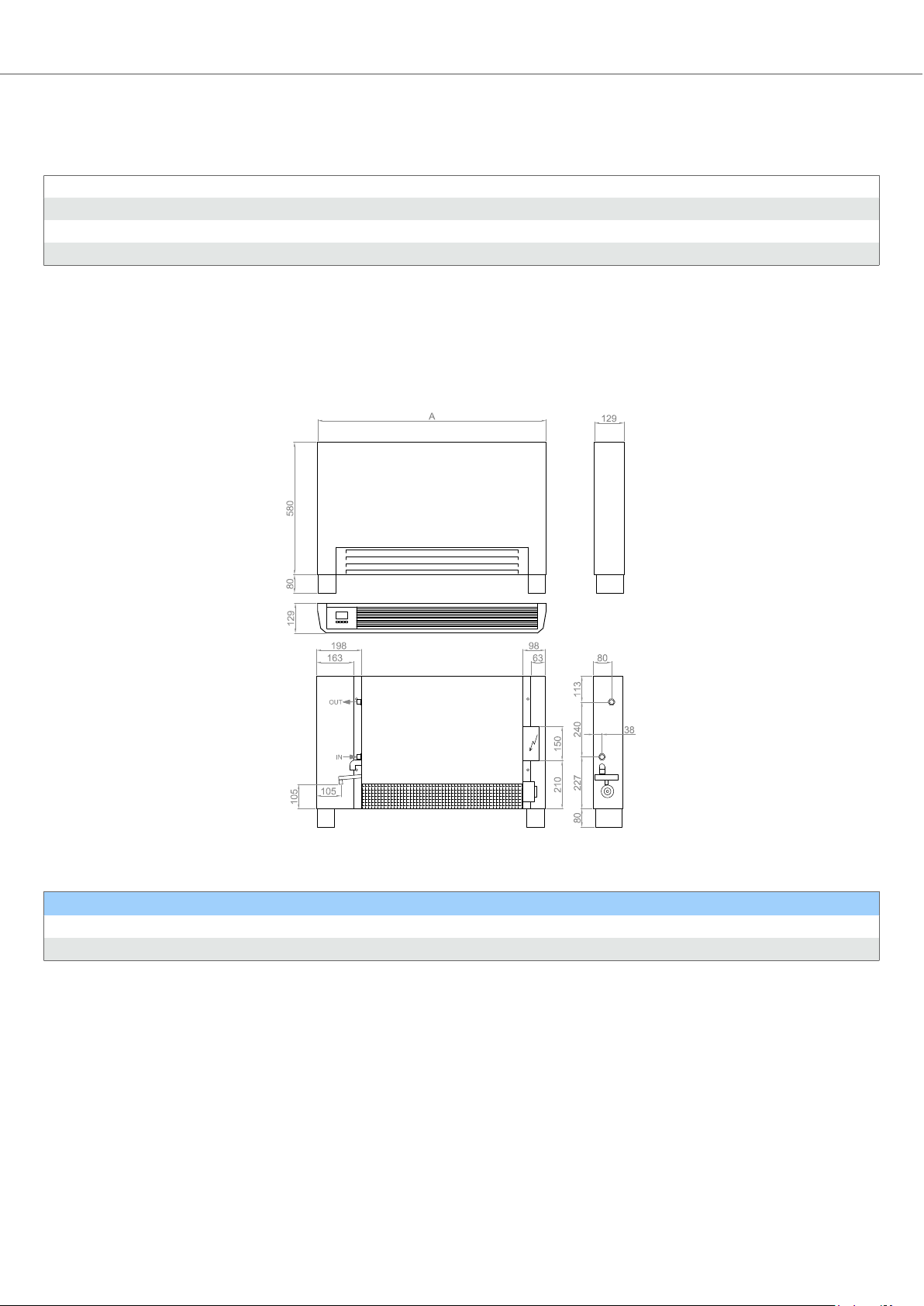
2.6. Dimensions ....................................................................................................................................... 8
2.6.1. IRIS Slim - vertical with outer casing ........................................................................................ 8
2.6.2. IRIS Slim - vertical built-in ....................................................................................................... 9
3.
Lifting, unpacking and content checking ......................................................................................................... 11
3.1. Lifting and shipping ........................................................................................................................... 11
3.2. Unpacking ........................................................................................................................................ 11
3.3. Content checking .............................................................................................................................. 11
4.
Installation ................................................................................................................................................... 12
4.1. Preparing for installation..................................................................................................................... 12
4.2. Positioning ....................................................................................................................................... 13
4.3. Electrical supply ............................................................................................................................... 14
4.3.1. Hydraulic connections ............................................................................................................ 14
4.3.2. Electrical connections ..............................................................................................................17
4.4. Supporting feet installation (optional accessory) ................................................................................. 18
5.
Control and regulation devices ..................................................................................................................... 20
5.1. Controls .......................................................................................................................................... 20
6.
Maintenance ................................................................................................................................................ 21
6.1. Ordinary maintenance ...................................................................................................................... 21
6.1.1. Cabinet cleaning .................................................................................................................... 21
6.1.2. Filter cleaning ........................................................................................................................ 21
6.2. Extraordinary maintenance ................................................................................................................ 23
6.2.1. Motor and fan ........................................................................................................................ 23
6.2.2. Battery ................................................................................................................................... 24
6.3. Troubleshoouting .............................................................................................................................. 25
6.3.1. Troubleshooting IRIS Slim ...................................................................................................... 26
7.
Disposal ...................................................................................................................................................... 27
IRIS SLIM / IN
Rossato Group Srl 3

1. Introduction
PRIMA DI EFFETTUARE QUALSIASI OPERAZIONE SULLE MACCHINE GLI OPERATORI ED I TECNICI INCARICATI
DEVONO LEGGERE ATTENTAMENTE BEFORE CARRYING OUT ANY OPERATION ON THE MACHINES, THE
OPERATORS AND TECHNICIANS IN CHARGE MUST CAREFULLY READ THE INSTRUCTIONS CONTAINED
IN THIS MANUAL AND FOLLOW THEM WHILE CARRYING OUT THE WORK.
IF YOU HAVE ANY DOUBTS ABOUT THE CORRECT INTERPRETATION OF THE INSTRUCTIONS, PLEASE
CONTACT OUR SUPPORT SERVICE FOR CLARIFICATION.
1.1. General information
The installation and maintenance of the device is to be carried out by qualified persons (each for his own task) who have
received the necessary instructions. These operations must be carried out in accordance with the safety regulations in
force. These regulations may concern, for example, safety at work (use of eye and hand protection, etc.), electrical
equipment and installations, pressure vessels, refrigeration equipment, lifting equipment.
The manufacturer/vendor shall not be liable for any damage to persons or property resulting from failure to comply with
the requirements set out in this manual, failure to perform regular maintenance or use of non-original spare parts or
alteration of the condition of the product compared to the time of receipt. Furthermore, in these cases the official warranty
on the product is considered to have expired. This manual must be kept with the machine.
1.1.1. Description of symbols
DANGER
DANGER:
This symbol indicates accident prevention regulations for the user.
Failure to comply with these instructions may result in death or serious or permanent damage to health.
CAUTION
ATTENTION:
This symbol indicates danger to the unit and its components.
Failure to follow these instructions may result in damage to the unit and/or its components.
IMPORTANT
WARNING:
This symbol indicates rules of conduct for the user.
Failure to comply with these instructions may result in malfunction of the unit or exclusion from the warranty.
NOTE
NOTE:
This symbol indicates useful information.
1.1.2. General information
This instruction manual refers to:
TYPE OF MACHINE:
SERIES:
This manual contains the main information indicated in the table of contents, is an integral part of the machine and must
be kept carefully until the machine is finally dismantled in order to allow reference for future updates.
In the event of damage that renders the copy of the manual in your possession unusable, you may ask for a copy:
Rossato Group Srl
IRIS SLIM / IN
Rossato Group Srl 4

Via del Murillo, km 3,500
04013 Sermoneta (LT) - Italy
Tel. +39 0773 844051
Web: www.rossatogroup.com
E-mail: assistenza@rossatogroup.com
specifying the type of machine and the serial number on the machine's name plate.
The official language chosen by the manufacturer is: Italian
No liability is accepted for translations into other languages which do not conform to the original meaning.
This manual reflects the state of the machine at the time of delivery and may not be considered inadequate simply
because it has been subsequently updated on the basis of new studies or experience.
You may receive future revisions or updates to integrate and consider.
Rossato Group Srl reserves the right to update production and manuals without the obligation to inform users of
previously supplied machinery. The notification of proposals to update manuals and/or machines are in any case to be
considered forms of courtesy.
The Customer Service is in any case available to provide, upon request, information on the updates that Rossato Group
Srl has made to the devices.
IRIS SLIM / IN
Rossato Group Srl 5

2. Unit description
2.1. Destination of use
Iris Slim units are designed for heating, cooling, dehumidification and filtration of residential and tertiary environments
(offices, public premises, or similar).
2.2. Unintended use
Following applications are not permitted:
•Outdoor operation
•Operation in humid or explosive or dusty environments
•Operation in corrosive environments, particularly for the aluminium fins of the battery
•Operation in environments subject to electromagnetic interference
The machines are not intended for use by persons (including children) with reduced physical, mental or sensory
capabilities, or persons who have not received adequate information, unless they are supervised by a person responsible
for their safety.
2.3. Identification plate
Serial number label
The serial label is located on the unit and allows all the machine's characteristics to be traced. The serial label must never
be removed.
The serial number label carries the information required by the regulations.
Serial number
It uniquely identifies each machine.
It allows the identification of specific spare parts for the machine.
Request for technical assistance
Make a note of the characteristic data on the identification label and write them down on the service request form if
necessary. In case of a service request, always provide:
•type of unit
•serial number
•year of purchase
The request for intervention must be made by filling in the appropriate form on the website www.rossatogroup.com in the
"Technical Assistance" section.
IRIS SLIM / IN
Rossato Group Srl 6

2.4. Technical features
SIZE 601 801 1001 1201
Air flow rate MAX m3/h 180 340 500 600
MED m3/h 130 235 340 415
MIN m3/h 60 120 175 215
Cooling performance (Ambient air D.B.T. 27°C - D.B.19°C - Water 7 -12°C)
Total cooling capacity MAX kW 0,83 1,61 2,56 3,28
MED kW 0,66 1,24 1,93 2,48
MIN kW 0,37 0,74 1,14 1,46
Sensible cooling capacity MAX kW 0,68 1,32 2,02 2,53
MED kW 0,53 0,98 1,49 1,88
MIN kW 0,28 0,56 0,85 1,07
Water flow rate MAX l/h 142 277 440 564
MED l/h 114 214 332 427
MIN l/h 63 127 196 250
Pressure drop at the exchanger MAX kPa 9 6 18 33
MED KPa 6 4 11 20
MIN KPa 2 2 4 8
Heating performance (Ambient air D.B.T. 20°C - Water 45-40 °C)
Heating capacity MAX kW 0,97 1,88 2,83 3,51
MED kW 0,75 1,4 2,07 2,59
MIN kW 0,4 0,8 1,18 1,47
Water flow rate MAX l/h 169 325 490 607
MED l/h 131 242 359 449
MIN l/h 69 137 204 254
Water pressure drop at the exchanger MAX kPa 10 7 19 33
MED kPa 7 5 11 19
MIN kPa 2 2 4 7
Sound levels
Sound power MAXdB (A) 53 53 54 54
MED dB (A) 45 46 46 46
MIN dB (A) 37 38 38 38
Sound pressure MAX dB (A) 44 44 45 45
MED dB (A) 36 37 37 37
MIN dB (A) 28 29 29 29
Electrical data
Absorbed power MAX W 11 19 20 24
MED W 6 11 12 15
MIN W 5 6 7 9
Max. motor power consumption A W 0,1 0,2 0,2 0,2
IRIS SLIM / IN
Rossato Group Srl 7

2.5. Operating limits
Tabella 1. Operating limits
Power supply 220 - 240 V / 50 Hz
Battery inlet water temperature 5 - 70 °C
Air intake temperature 10 - 35 °C
Air intake relative humidity 10 - 70 %
It is advisable to operate the device at the extremes of these operating limits for short periods only, as operation for long
periods may reduce the normal life of the components.
2.6. Dimensions
2.6.1. IRIS Slim - vertical with outer casing
Figura 1. IRIS Slim - vertical with outer casing
Tabella 2. Dimensions and weight
Size 601 801 1001 1201
A (mm) 600 800 1000 1200
Weight (kg) 17 20 23 26
IRIS SLIM / IN
Rossato Group Srl 8

2.6.2. IRIS Slim - vertical built-in
Figura 2. IRIS Slim - vertical built-in
Figura 3. Outer casing
IRIS SLIM / IN
Rossato Group Srl 9

Figura 4. Front panel
Tabella 3. Dimensions and weight
Size 601 801 1001 1201
B (mm) 305 505 705 905
L (mm) 715 915 1115 1315
L1 (mm) 795 995 1195 1395
Weight (kg) 9 12 15 18
IRIS SLIM / IN
Rossato Group Srl 10

3. Lifting, unpacking and content checking
3.1. Lifting and shipping
When unloading and positioning the unit, great care must be taken to avoid sudden or violent manoeuvres. Internal
transport should be carried out carefully and gently, avoiding using the components of the machine as a point of force.
CAUTION
In all lifting operations, ensure that the unit is securely anchored to avoid accidental tipping or falling.
The machines are delivered packed in cardboard boxes. Do not put weights on top of the boxes and do not stack more
boxes than they are at the time of delivery.
Check that the identification label bears the same code as ordered and that there is no damage to the packaging or the
product. In case of non-conformity, contact the manufacturer or seller immediately and do not proceed with the
installation.
Do not dispose of the packaging in the environment; dispose of it in accordance with the regulations on waste disposal.
3.2. Unpacking
The unit's packaging must be removed with care, avoiding possible damage to the machine; the materials that make up
the packaging are of different types, wood, cardboard, nylon, etc. It is good practice to store them separately and deliver
them for disposal or possible recycling, to the companies in charge of this purpose, thus reducing their environmental
impact. It is a good idea to store them separately and hand them over for disposal or recycling to the appropriate
companies to reduce their environmental impact.
3.3. Content checking
Upon receipt of the delivery ensure that:
•The components have not been damaged in transit or the packaging has not been tampered with and parts have not
been removed.
•That the material delivered corresponds to what is indicated on the transport document by comparing the data with the
serial number label placed on the packaging.
In case of damage or malfunction:
•Immediately note the damage on the transport document and include the words: 'Withdrawal with reservation due to
obvious shortages/transport damage'.
•Report the transport damage to the supplier by e-mail, including photos and a detailed description.
IMPORTANT
Complaints must be made within 8 days of receipt.
Complaints made after this deadline are not valid and will not be accepted.
IRIS SLIM / IN
Rossato Group Srl 11

4. Installation
4.1. Preparing for installation
Remove the cardboard packaging and all external polystyrene side protections before installation. The unit should always
be handled by two people and should only be grasped on the adequately resistant points (main metal structure), taking
care not to damage the less resistant parts, in particular the filters, grills and control.
If the optional feet are present, install them as described in the specific paragraph. For units
equipped with a cabinet, it must first be removed by following the procedure below.
Using a Phillips screwdriver with a maximum diameter of 3.5 mm, remove the screw from the hole at the right end of the
front intake grille. Rotate forward and lift the suction grille to remove it.
Remove the screws that secure the cabinet to the fan-coil structure, behind the intake grille.
Remove the screw at the right end of the discharge grille (if it has blades pointing forwards) or left end (if it has blades
pointing backwards) and remove the grille by releasing it from the side opposite the screw.
Remove the screws securing the cabinet beam to the fan-coil structure and remove the cabinet by lifting it upwards.
IRIS SLIM / IN
Rossato Group Srl 12

At the end of the installation, it will be necessary to reassemble all the components in the reverse order in which they
were disassembled. It is absolutely forbidden (serious risk of personal injury) to use the unit if any components have been
correctly reassembled.
The unit has four slots for fixing it to the wall using dowels and screws.
Weight U.M. 601 801 1001 1201
Weight kg 17 20 23 26
Battery inner volume liters 0.47 0.8 1.13 1.46
Drill the wall with the centre distances shown and insert the four dowels into the holes.
601 801 1001 1201
A (mm) 351 551 751 951
Secure the unit to the wall with four screws (washers may be required depending on the size of the screw heads). At the
end of the installation the unit must be perfectly horizontal or with a slight slope in the direction of the condensate drain.
Installations with a slope opposite to the condensate drain are not permitted as this can prevent natural drainage.
4.2. Positioning
The unit must be installed on a wall which must be perfectly vertical (90° to the floor).
Observe the minimum dimensions shown in the figure, which are necessary for the smooth installation and correct
operation of the unit.
IRIS SLIM / IN
Rossato Group Srl 13

The unit must not be exposed to direct sunlight or heat sources. Provide a position in the room so that the unit can treat
the whole room uniformly, without directly hitting the occupants with the air flow.
4.3. Electrical supply
4.3.1. Hydraulic connections
The machine is equipped with a battery suitable for working with water, possibly mixed with glycol.
To avoid the formation of condensation on the surface of the unit during the summer period, when the fan is not running, it
is recommended to interrupt the flow of chilled water by means of a motorised valve.
All pipes, particularly those for chilled water, must be insulated to prevent condensation dripping.
To facilitate maintenance, it is advisable to provide manual ball valves, so that the machine can be shut off from the
system.
When connecting the pipes, in order not to touch the coil and valve pipes, it is recommended to use a spanner and
counter spanner.
The valves can be pre-installed or supplied in kit (to be assembled by the installer).
In any case, take care to respect the indications regarding water inlet and outlet.
IRIS SLIM / IN
Rossato Group Srl 14

Vertical version without valve
Horizontal version without valve
With valve V23
After completing the hydraulic installation and charging the system, the coil must be vented using the needle valve
provided. Repeat the venting operation after starting the circulation pump, until it is certain that all bubbles have been
eliminated.
A = Drain valve
IRIS SLIM / IN
Rossato Group Srl 15

Before connecting the condensate drain pipe, check that the main tray is level or slightly sloping towards the drain. In the
vertical version, also check that the auxiliary tray is correctly fixed to the side and that the rubber elbow is adherent to the
drain of the main tray. In horizontal versions, check that the rubber discharge pipe is adherent to the metal elbow of the
main pan.
A = Gomito di gomma
B = Vaschetta ausiliaria
Use a drain pipe with a diameter of at least 16 mm. It is advisable to use a white water drain; if there is a possibility of
odours rising, a siphon must be installed. The slope of the pipe must be constant and not less than 1%; if it is necessary
to overcome counter-slopes, install a drain pump (follow the instructions on the pump installation sheet), the pump must
in any case be installed below the level of the unit's tray.
For vertical units, connect the condensate drainage pipe to the auxiliary tray. For horizontal units, extend the existing
drainage pipe, which is connected to the metal elbow of the main tray. When mounting the front panel, make sure that the
drainage pipe is never at an angle.
After completing the installation of the condensate drain, pour at least 2 litres of water into the tray with a bottle (slowly, in
small doses over a period of 5 minutes) and check that it flows correctly.
3-Way Valve Kit Installation (Optional Accessory)
The valves can be supplied either assembled to the unit or in kit form (disassembled components). Valves supplied in kit
form must be assembled to the unit as shown in the figures in the dedicated section.
Always place flat fibre or rubber seals between each hydraulic element (e.g. between valve and pipe or between battery
and pipe).
Insulate all pipes (upstream and downstream of the valves) and the valve body itself to prevent condensate dripping out
of the auxiliary tank.
Make sure that the actuator is facing upwards or at least horizontally to the valve body. Installations with the actuator
facing downwards are not permitted.
IRIS SLIM / IN
Rossato Group Srl 16

3-way / 4-port valve kit assembly
After assembling the kit, remove the protective cap from the valve and secure the actuator by means of the threaded ring
nut (the shape of the component may differ from that shown depending on the type).
A = Actuator
B = Protecting cap
4.3.2. Electrical connections
Provide a manual disconnect near the unit so that it can be disconnected from the power line during maintenance
operations.
Provide a fuse or circuit breaker to protect the unit.
The power supply cables must be sized taking into account the maximum absorption of the machine, as indicated on the
label and in the technical manual, in any case not less than 0.75 sq. mm.
Check that the mains voltage and frequency is 230 V - 50 Hz.
Before carrying out any maintenance work on the machine, make sure that the main power supply is switched off and
cannot be switched on unintentionally. Before opening the electrical box, wait at least 60 seconds after the power supply
has been switched off. In any case, after opening the electrical box, before touching the board or the electrical
connections, check with a tester (set to V direct) that the voltage at the ends of the capacitor is lower than 38 V (for this
purpose, measuring points are provided on the board itself). Do not continue with the intervention if the voltage is higher
than 38 V.
IRIS SLIM / IN
Rossato Group Srl 17

The unit has the hydraulic and electrical connections on opposite sides; if the electrical connection has been made on the
same side as the hydraulic connections, it is possible to reach the opposite side by running the wires over the backrest;
the wires so arranged will then be covered by the crossbar of the cover unit.
To remove the switchboard cover, unscrew the two screws that secure it to the side of the unit.
Before proceeding with the electrical installation, refer to the unit-specific wiring diagram supplied with the unit.
After completing the electrical installation, replace the cover of the electrical panel and secure it with the two screws.
Wiring diagrams IRIS SLIM
Refer to the document supplied with the unit for the wiring diagrams.
4.4. Supporting feet installation (optional accessory)
Remove the cabinet and filters (as described in the specific paragraphs). Fix the two galvanised sheet metal brackets to
the left and right sides with the screws provided.
IRIS SLIM / IN
Rossato Group Srl 18

Fix the two feet (right and left, not interchangeable) with six self-tapping screws as shown in the figure using the holes
provided. Finally, make sure that they are firmly attached to the structure of the fan-coil.
Remove the filters and the cabinet.
IRIS SLIM / IN
Rossato Group Srl 19

5. Control and regulation devices
5.1. Controls
The unit is supplied with SP3-BLDC power board already mounted on the machine and TOP3 keypad. The unit can be
controlled in one of the following ways:
•From TOP3 wall keypad
•From TOP3 - BI keypad (mounted on board)
•As slave of a master unit
•From supervisory system (MODBUS) with optional card
Depending on the configuration chosen, air and/or water temperature probes may be required, refer to the control manual
for more information.
IRIS SLIM / IN
Rossato Group Srl 20
Table of contents
Other Rossato Dehumidifier manuals
Popular Dehumidifier manuals by other brands

Santa Fe
Santa Fe Compact 2 Installation and operation instructions

Desert Aire
Desert Aire LW Installation and operation manual

Trotec
Trotec TTR 250 EX operating manual

Stadler Form
Stadler Form Theo operating instructions

Harison
Harison HD Series user manual

Morris
Morris Premier plus MDD-10251W instruction manual