Rossi Welders Cut 40 User manual

Inverter Welder
Cut 40 Cutter Machine
User Manual
RETAIN THIS MANUAL FOR FUTURE REFERENCE
PLEASE READ THIS MANUAL CAREFULLY BEFORE USE

Inverter Welder - Cut 40 Cutter Machine
i
Table of Contents
Introduction ................................................................................................................................................................. 1
Safety............................................................................................................................................................................ 1
Warning..............................................................................................................................................................1
Electric Shock may be Fatal to Life....................................................................................................................2
Smoke may be Harmful to Your Health.............................................................................................................2
Arc-Emission may be Harmful to Your Eyes and Skin ......................................................................................2
Too Much Noise may be Harmful to Your Hearing............................................................................................2
Ask for Professional Help...................................................................................................................................2
Technical Data ............................................................................................................................................................ 3
Parts Schematic.......................................................................................................................................................... 3
Air Adjuster Assembly Diagram .........................................................................................................................4
Power Input Diagram..........................................................................................................................................4
Installation................................................................................................................................................................. 5
Input Cable Connection......................................................................................................................................5
Output Cable Connection...................................................................................................................................6
Checking......................................................................................................................................................................... 6
Pre-Operation.....................................................................................................................................................6
Operation....................................................................................................................................................................... 6
Operating Environment......................................................................................................................................6
Notes on Cutting.................................................................................................................................................6
Maintenance ................................................................................................................................................................ 7
Troubleshooting ......................................................................................................................................................... 7
Technical Specifications .......................................................................................................................................... 8

Inverter Welder - Cut 40 Cutter Machine
1
Introduction
Thank you for purchasing our welder/cutter.
For your safety, please read this manual and understand its contents before operation.
The Inverter Plasma Cutter is made by the most internationally advanced inverter technology. 50/60 Hz
frequency is inverted to high frequency (frequency that is over 100 KHz) by V-MOSFET, and then reduces the
voltage and rectification current. The inverter power supply generates powerful DC welding current through
PWM technology. Because the inverter technology of the switch power is used, the dimensions and weight of
the main transformer has been reduced significantly and efficiency has increased by 30%. The Piloting Arc
System can strike arcs easily with the principle of high-frequency oscillation. It can supply gas ahead of time and
it can also turn off gas at a later time.
Our Inverter Plasma Cutter has the following characteristics:
•
Stabilizing.
•
Reliability.
•
Lightness.
•
Energy-saving and does not generate any noise.
•
High-speed cutting.
•
Cuts smoothly; no need for further polishing.
The Inverter Plasma Cutter can be used in a wide variety of ways; it is suitable for cutting stainless steel, alloy
steel, mild steel, copper and other coloured-metal materials.
We welcome you to use the product of our company and make suggestions; we will try our best to improve our
products and services.
Guarantee
We give our unreserved guarantee that the Inverter Welding and Cutting Power Source series comply with
IEC974 international safety standard; maintenance for one year from the date of purchase.
Safety
Warning
•
Make sure that the working area is adequately ventilated.
The Inverter Plasma Cutter is light and compact. The electromagnetic fields are generated by high currents.
Natural wind will not sufficiently cool down the components, there is one axial-flow fan within the machine in
order to cool it down.
NOTE: The exhaust shutter must not be blocked or covered within a 0.3m radius from the machine to
objects. Make sure to always keep improving the ventilation of the environment; it is very important for the
Inverter Plasma Cutter.
•
Do not overload!
The limits of the cutting current is strictly in accordance to the maximum allowable current with all kinds of
duty cycles.
Do not exceed the working load in order to prevent the Inverter Plasma Cutter from shortening its life as well
as to avoid burning up the machine.

Inverter Welder - Cut 40 Cutter Machine
2
•
Do not overcharge!
The power voltage range of the Inverter Plasma Cutter is in accordance to the main technical data sheet.
Voltage automatic compensation circuit will prevent it from exceeding the allowable range. If the power
voltage is too high, the internal components could be damaged. User must exercise caution.
•
There is a grounding screw, which is marked “grounding” behind the Inverter Plasma Cutter. Make sure that
the mantle is grounded reliably by a cable whose width is 6 millimetres square in order to prevent electricity
from leaking and producing electro-static.
•
The inter-heat variable component will start if the machine exceeds its duty cycles. That will cause the
Inverter Plasma Cutter to stop working immediately and the red diode to light up. User does not need to
break the circuit; the fan will continue working in order to cool down the machine. Once the temperature is
reduced to a more suitable range, the machine can then be operated again.
•
During welding or cutting, do not switch in-between functions. It could damage the machine.
•
Plug-off the air plug that is connected to the electrode holder to make sure that the holder is separated from
the main machine to avoid an electric shock.
•
A certain switch is needed to protect the machine from voltage-leakage.
•
Pl ease use high-quality welding and/or cutting tools.
•
Operators should be trained and qualified for welding or cutting.
Electric Shock may be Fatal to Life
•
Set the earth cable to standard.
•
Do not touch electrical parts with bare hands, wet hands and/or clothes.
•
Make sure that you and the working piece are properly insulated.
•
Make sure that you prioritise your safety while working.
Smoke may be Harmful to Your Health
•
Keep your head out of any smoke.
•
When welding or cutting, make sure that the air is well-ventilated to avoid breathing in the smoke.
Arc-Emission may be Harmful to Your Eyes and Skin
•
Wear appropriate welding or cutting mask and clothes to protect your eyes and skin.
•
Use suitable screens or curtains to protect the look-ups from the emission.
•
The welding or cutting sparks may cause fire; make sure that there are no flammable materials nearby in the
working place.
Too Much Noise may be Harmful to Your Hearing
•
Please wear protective gears like earmuffs to protect your ears from loud noises.
•
Warn the look-ups of the harm the noise may cause.
Ask for Professional Help
•
If you have any problems in setting up or operating the tool, please consult this manual first.
•
If you still can’t understand after reading this manual, please contact your supplier or manufacturer to get
professional help.

Inverter Welder - Cut 40 Cutter Machine
3
Technical Data
Item/Data Cut-30 Cut-40 Cut-50 Cut-60/220 Cut-60/380
Power Single Phase Single Phase Single Phase Single Phase Three Phase
Voltage (V) 220 ± 15% 220 ± 15% 220 ± 15% 220 ± 15% 380 ± 15%
Rated Input Power (KVA) 3.2 4.7 6.5 8.7 9
No-Load Voltage (V) 220 220 225 240 240
Rated Output Current (A) 30 40 50 60 60
Rated Output Voltage (A) 90 100 110 120 120
Duty Cycle 60% 60% 60% 60% 60%
Pilot Arc Model HF HF HF HF HF
Burner Inner Diameter (mm) 1.0 1.0 1.0 1.2 1.2
Pressure of Air Compressor
(Mpa) 0.4 0.45 0.45 0.5 05
Thickness (mm) 1-8 1-12 1-16 1-23 1-23
Weight (kg) 8 9 13 16 17
Dimensions (mm) 390 X 155 X
250 390 X 155 X
250 425 X 205 X
355 425 X 205 X
355 510 X 200 X
350
Parts Schematic

Inverter Welder - Cut 40 Cutter Machine
4
Air Adjuster Assembly Diagram
Power Input Diagram

Inverter Welder - Cut 40 Cutter Machine
5
Installation
Input Cable Connection
See diagrams above.
•
Each machine is equipped with a power cable, which must be connected to the correct voltage class
according to the input voltage of the Inverter Plasma Cutter. If the Inverter Plasma Cutter, whose power
voltage is 220V, is connected to the wrong AC 380V, it will cause the components of the machine to burn up.
•
Make sure that the power cable is connected to the power switch reliably so as to avoid it from oxidising.
Make sure that the power voltage stays within the recommended range.

Inverter Welder - Cut 40 Cutter Machine
6
Output Cable Connection
•
Make sure that the tube of compressed air is firmly connected to the copper connector by a high-pressure
rubber tube.
•
Make sure that the copper screw at the other end of the torch is connected to power-up the integration
terminal, then tighten them in a clockwise direction (preventing it from leaking gas). For the mobile plug at
the other end of the grounding cable pincer, make sure to connect it to the positive terminal of the front
panel, then tighten it.
•
Make sure that the air plug of the torch is connected to the switch connector of the panel (if it is an arc-
supporting cutter, the arc-supporting cable of the torch should be connected to the terminal of the arc-
supporting).
Checking
•
Check if the Inverter Plasma Cutter is grounded reliably according to required standards.
•
Check if all of the connectors are connected firmly.
•
Check if the power voltage is correct.
Pre-Operation
1. Open the power switch of the front panel, switch in into the “ON” position. With this, the time indicator of the
power switch is also turned on. Screen will then show the current volume.
2. Adjust the gas pressure in a way that is suitable to the machine, then open the valve of compressed air.
3. Press the control knob of the torch, which should start the electromagnetic valve. After which, the sound of
HF arc-strikes can be heard and that the burner of the torch should be emitting gas (Burner of the arc-
supporting cutter should spurt).
4. Make sure that the cutting current is suitable for the machine according to the thickness of the cutting piece
flame.
5. The distance from the copper tip to the work piece should be 1mm (Farther if it is the arc-supporting cutter).
Press the knobs of the torch and the burn and strike arc. Sparks of HF arc-strikes will diminish immediately.
User can now begin to cut.
Operation
Operating Environment
•
The Inverter Plasma Cutter can perform in an environment where conditions are particularly harsh and with
outside temperatures between -10 and +40 degrees centigrade, with a dampness level of max. 80%.
•
Avoid using the Inverter Plasma Cutter under direct sunlight; do not drop the Inverter Plasma Cutter.
•
Keep the Inverter Plasma Cutter dry and avoid letting it make contact with water and other liquids.
•
Do not use the Inverter Plasma Cutter in an environment where the condition is filled with a high
concentration of dust and/or corrosive gases in the air.
Notes on Cutting
•
Make sure that the copper tip should not connect to the work piece directly when user is cutting. Torch
should be held inclined and 1mm from the inter-hole of the copper tip to the work piece in order to protect the
copper tip.
•
As an arc-supporting cutting machine, if the arc-supporting frequency is down or if there is no arc-supporter,
user can get rid of the oxidised film of the inner electrode with an abrasive paper. Then the machine can be
operated normally.

Inverter Welder - Cut 40 Cutter Machine
7
Maintenance
•
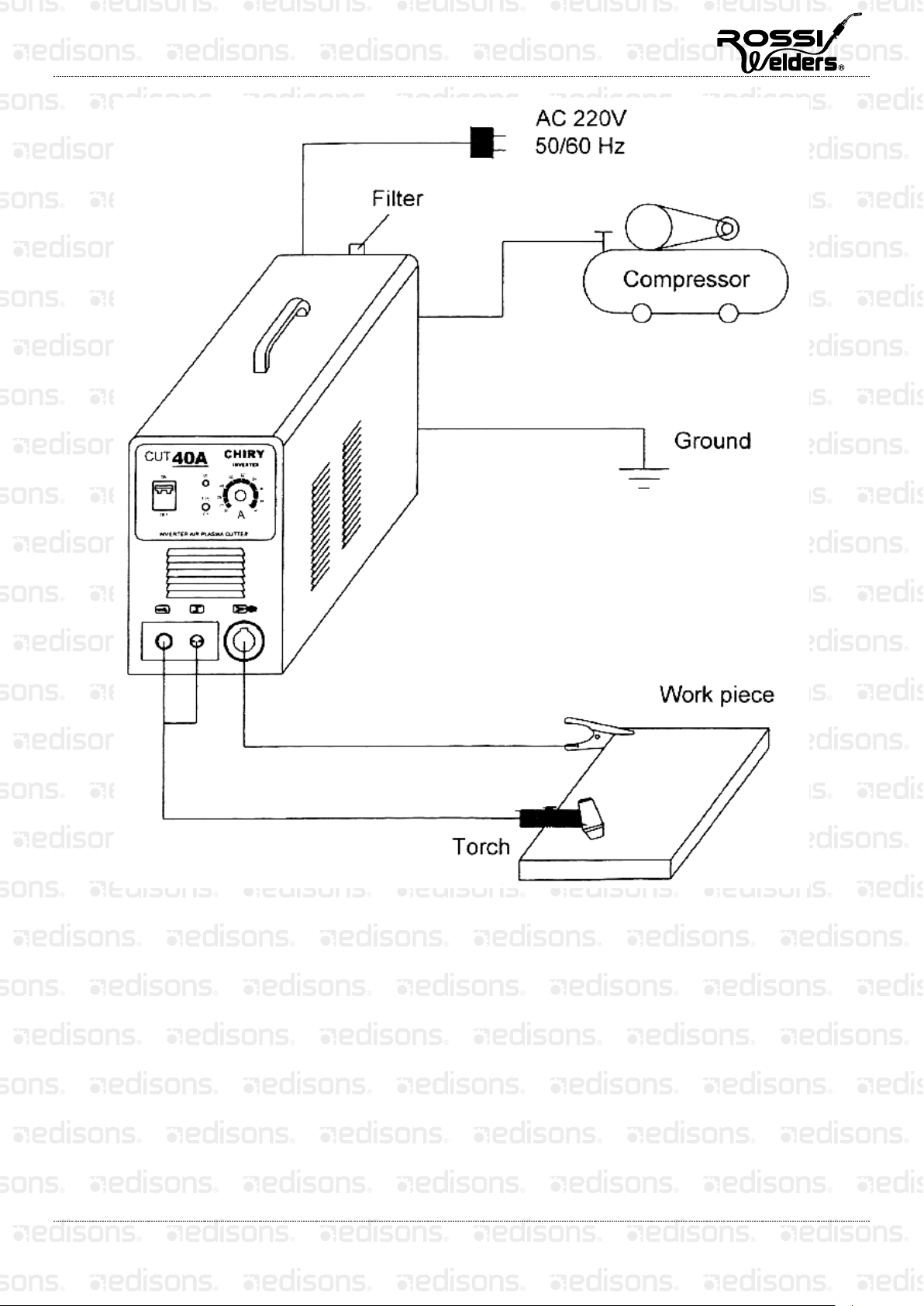
Remove dust and/or dirt with compressed air regularly. If the Inverter Plasma Cutter is placed in an
environment where the condition is filled with smoke and/or dust, the Inverter Plasma Cutter must be
cleaned of dust/dirt every day.
•
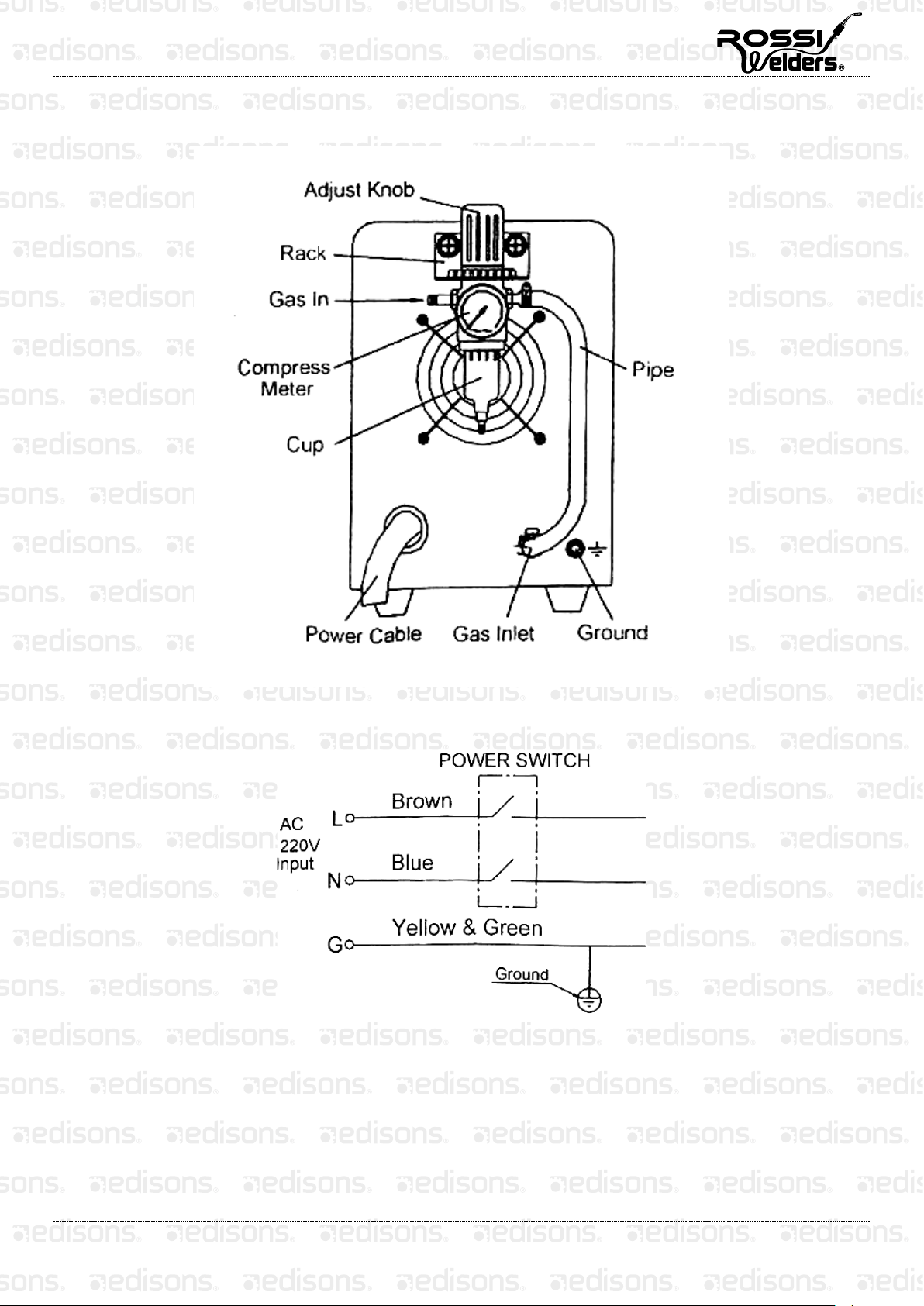
Adequate pressure is set for cutting in order to protect the little components in the machine.
•
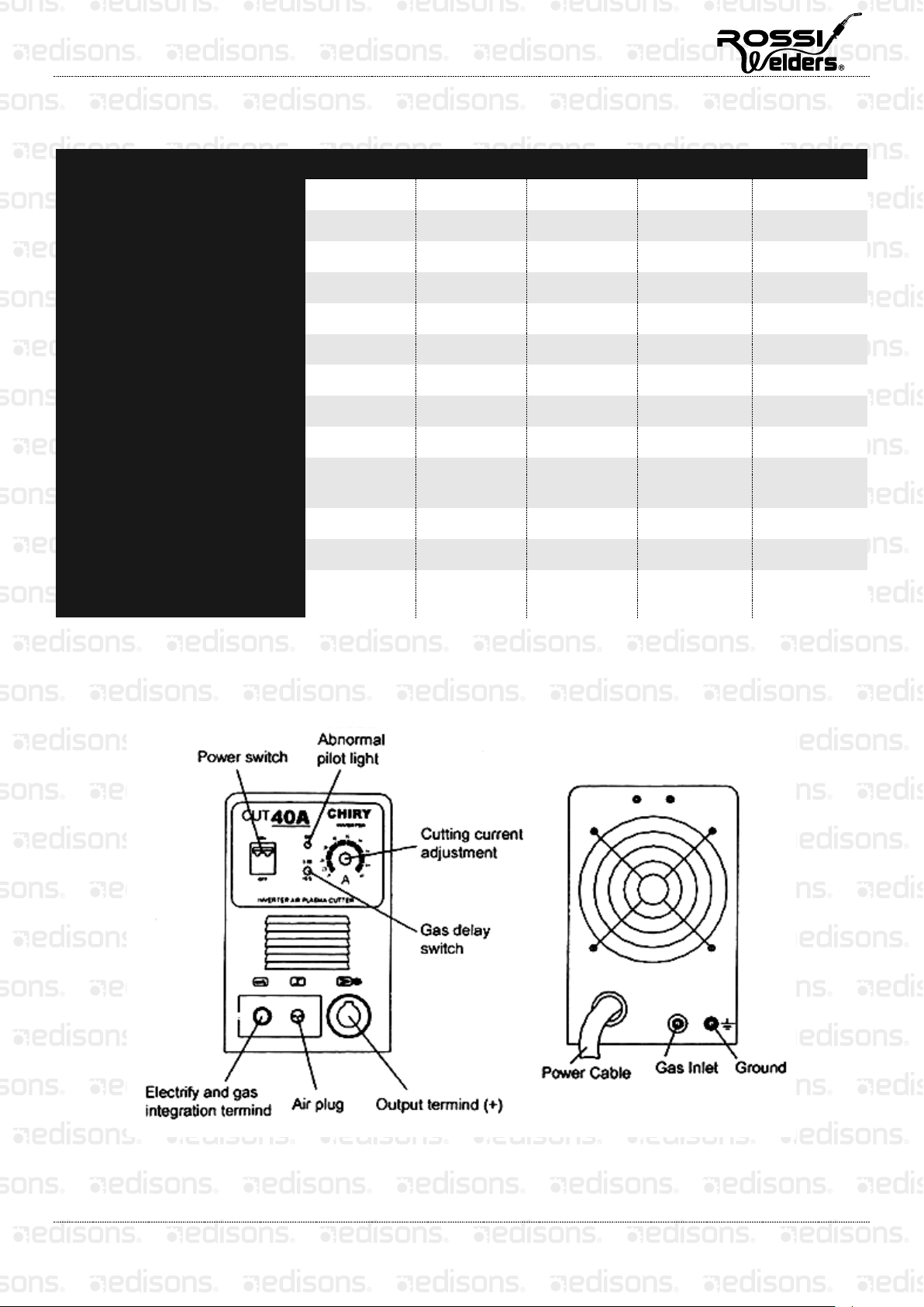
Check the electrical connectors and make sure that the connectors are connected firmly (especially when
connecting and inserting components). If not, tighten the connectors.
•
Avoid contact with water or other liquids. If the machine has been exposed to wetness/dampness, it must be
dried immediately and measure the insulation by meters. After ascertaining that there are no problems, the
machine can then be operated again.
•
If the Inverter Plasma Cutter will not be used for a long time, it should be put in its own packing box and
stored in a dry environment.
Troubleshooting
Faults Solutions
The power pilot light isn’t on, and the
fan isn’t working; no cutting voltage
output
The power switch is broken.
Check whether the electric net connected to the input wire has electricity.
Check whether the input cable has short-circuited.
The power switch is turned on, but
the fan isn’t revolving or only
revolving slowly; there is no cutting
voltage output.
It may be wrongly connected to the 380V power supply, thus causing the
over-voltage protection to kick in. Re-connect it to a 220V power supply, then
restart the machine.
The fan is on and the warning pilot
light is not on; no HF electricity being
emitted; cannot start the arc.
The voltage from the power board to the MOSFET should be about DC308.
−Whether it short-circuited or whether the bridge wire is well- connected.
−There are four capacitors on the bottom board, one of which may be
leaking; just replace it.
The assistant power supply is abnormal, it should be DC24V.
Check all of the connections in the machine.
Something is wrong with the control circuit, find the problem or contact the
seller.
The warning pilot light is off; no
sound when electricity has been
released; no cutting voltage output.
The welding cable is broken.
The earth cable is broken or it is not connected to the work piece.
The “+” output terminal is not connected well.
The warning pilot light is not on; no
sound when electricity has been
released.
The primary wires of the transformer and the power board are not well-
connected; re-connect them.
The nozzle has been oxidised or too far away; remove the oxidisation on the
surface. Place the distance to 1mm.
The warning pilot light is on It may be due to the over-charge protection kicking in. Please turn off the
power until the warning pilot light is off, and let the machine recover.
It may be due to the over-charge protection kicking in. No need to turn it off,
just wait for two or three minutes; or there may be something wrong with the
inverter circuit. If so, unplug the power plug on the MOSFET of the main
transformer, and then restart the machine.
−If the warning pilot light is still turned on, turn off the machine and unplug
the HF arc-leading power plug, and then restart the machine.

Inverter Welder - Cut 40 Cutter Machine
8
If the warning pilot light is on, there is something wrong with the
MOSFET, check and replace the MOSFET.
If the warning pilot light is not on, there is something wrong with the
step-up transformer; if so, replace it.
−If the warning pilot light is not on:
There may be something wrong with the transformer on the centre
PCB. You can use the electric bridge to measure the transformer. L
= 0.9 - 1.6mH Q > 35.
There may be something wrong with the secondary rectifier. (Model:
F30U60DN) on the centre PCB; check and then replace it.
There may be something wrong with the connection (CN12) on the
centre board; check and then replace it.
The feedback circuit may have short-circuited.
The output current is not stable, or
out of the control of the
potentiometer; current is not stable.
The 1K potentiometer is broken; replace it.
The connections are not well-connected, especially the plug-ins.
Cutting power is not enough; arc is
not consistent
The
Current input voltage is too low.
The earth cable is too long or not well-connected.
The air pressure is too high or too low.
The nozzle and the electrode of the torch don’t match well or not good
enough, and the being given is too small.
If you still cannot solve the problem after consulting the above table, please contact the manufacturer or an
authorised service centre.
Technical Specifications
Input Voltage 220-240V 50Hz (10A Plug)
Output Current 20-40 Amps
Post Flow Timer 2.5-5 Seconds
Output Voltage 100V
Duty Cycle 60%
Input Air Pressure 0.45Mpa
Cutting Capacity 1-14mm
Pilot Arc Mode HF
Efficiency 85%
GENERATOR SAFE 5.5kVA recommended

Some experts believe the incorrect or prolonged use of almost any
product could causeserious injury or death. For information that
may reduce your risk of serious injury or death consult thepoints
below and additionally, the information available at
www.datastreamserver.com/safety
- Consult all documentation, packaging and
product labelling be fore use. Note that some
products feature online documentation which
should be printed and kept with the product.
- Check product for loose / broken / damaged /
missing parts, wear or leaks (if applicable) be fore
each use. Never use a product with loose / broken
/ damaged / missing parts, wear or leaks (if
applicable).
- Products must be inspected and serviced (if
applicable) by a qualified specialist every 6
months assuming average residential use by a
person of average weight and strength, ab ove
average technical aptitude, on a property
matching average metropolitan specification.
Intended use outside these guidelines could
indicate the product is not suitable for intended
use or may require more regular inspection or
servicing.
- Ensure all possible users of the p roduct have
completed an industry recognised training course
before being given access to the product.
- The product has been supplied by a general merchandise
retailer that may not be familiar with your specific applic ation or
your description of the application. Be sure to attain third party
approval for your application from a qualified specialist before use
regardless of prior assurances by the retailer or its representatives.
- This product is not intended for use where fail-safe operation is
required. As with any product (take an automobile, aircraft,
computer or ball point pen for example) there is always a small
chance of a technical issue that needs to be repaired or may
require replacement of the product or a part. If the possibility of
such failure and the associated time it takes to rectify could in any
situation inconvenience the user, business or employee or could
financially affect the user, business or employee then the product
is not suitable for your requirements. This p roduct is not for use
where incorrect operation or a failure of any kind, including but
not limited to a condition requiring product return, replacement,
service by a technician or replacement of parts could cause a
financial loss, loss of employee time or an in convenience
requiring compensation.
- If this item has been purchased in error considering the points
above simply contact the retailer directly for details of their
returns policies if required.
Table of contents
Other Rossi Welders Welding System manuals
Popular Welding System manuals by other brands

Holzmann
Holzmann EISA162 user manual

EWM
EWM MT221G X Series operating instructions

Taylor
Taylor SYSTEM CD200 SERIES operating manual

Thermal Dynamics
Thermal Dynamics PAK Master 150XL operating manual

GÜDE
GÜDE GPS-E 40 A Translation of the original instructions

Nupi
Nupi EloFIT SMARTFLEX 00E9001 Manual of use and maintenance

Spartus
Spartus ProMIG 335DP user manual

ims PRO
ims PRO POWERMIG 200-4S manual

Chicago Electric
Chicago Electric 68887 Owners manual & safety manual

WeldKing
WeldKing Mig Sonic 252S owner's manual

Thermal Arc
Thermal Arc 281 FABRICATOR Service manual

Castolin Eutectic
Castolin Eutectic MIG PULSE 3003 DP instruction manual