SA-02N
Supervised Wireless Magnetic Contact Sensor
Installation Manual
1
1. General Description
The SA-02N Supervised Wireless Magnetic Contact Sensor is a high-
performance intrusion sensor, developed with the highest level of
technology to make it ideal for residential and commercial applications.
1.1 Standard Features
Supervisor
Case and Back Tamper Detectors
ASIC and Microprocessor Technology
Up to 3-year battery life with SPS
Ultra-low current consumption
Readily replaceable 3.6 V – 1/2 AA Lithium battery
SMD component technology
LED Test Function
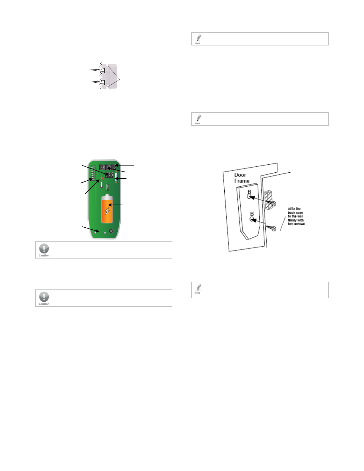
Figure 1: SA-02N
2. Technical Specifications
2.1 Electrical Characteristics
Battery CR123A 3V 1400 mAh (low battery signal when V =
2.5 V)
Current Standby – 3 to 8 uA; Transmit – 5 mA
Pulse Count Fixed at single pulse
Detect Range Sensitivity of up to 2 cm from magnet
Alarm Transmit One second
Indication LED EN/DIS
2.2 Physical Characteristics
Dimensions (H x W x D): 87 x 35 x 25 mm (3.5 x 13.8 x 1 in.)
Weight 37 g (1.30 oz) without battery
Standards FCC, CE, EN 50131-2-6, EN 50131-6, EN 50130-5,
EN 50130-4, Security Grade 2, Environmental Class
II
2.3 Environmental Characteristics
Operating Temperature
Range
-20°C to 50°C (-4°F to 122°F)
Operating Humidity
Range
Up to 95% (non-condensing) (max.)
RF Frequency Available in 433.92 MHz or 868.35 MHz, with 1 m
Watt
Installation Indoor
Magnet Standard magnet with plastic housing and wall
spacer, adjustable height
Tamper Switch 1 Detects removal of Magnetic Contact Sensor Front
Cover (protected by case tamper switch)
Tamper Switch 2 Detects removal of Magnetic Contact Sensor from
the wall or from corner mount (protected by rear
tamper switch)
Supervisor The supervisory signal is routinely transmitted to the
panels every 20 minutes, advising the Tamper
Status, Battery Status, and Event Activation Status to
the panel
3. Installation Recommendations
The SA-02N Magnetic Contact Sensor detects the opening and closing
of doors and windows, and transmits this information to the receiver
panel.
AVOID placing the Magnetic Contact Sensor near strong magnetic
or electrical fields other than the magnet with which it is intended
to be used; otherwise, performance may be affected and false
alarms may occur.
AVOID mounting on or near large metal surfaces and multiple
concrete/steel walls, as this may interfere or block the wireless
signals. Make sure to test the range from any location by using the
RF Test Procedure to ensure reception.
Install the magnetic contact sensor on windows or doors that
have firm hinges and firm locking action to prevent false
alarms associated with wind or bumping.
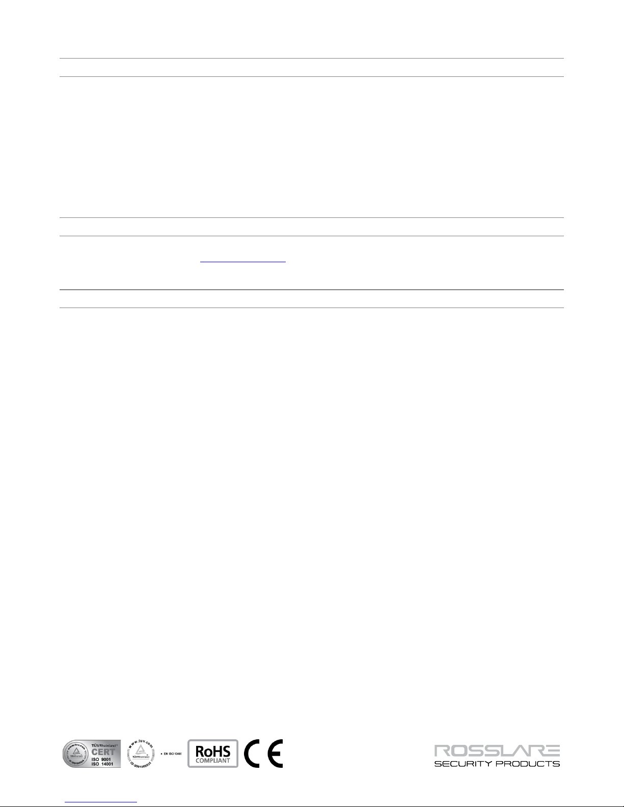
4. Installation Instructions
4.1 Selecting the Location
The location and mounting of the SA-02N affects both the
transmission range and the wear and tear of the transmitter. Preferably
the transmitter should be installed as close as possible to the receiver,
and mounted in a high location so that the transmission has less
interference.