| 9
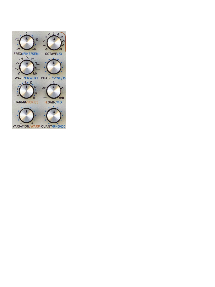
QUANT/RND/DC Selects the scale for the
Mix output quantizer.
Option 1: Adds random frequency variation
to all channels’ outputs.
Option 2: Adds a DC oset (+/- 12 semitones)
to the Mix output.
Mixed Mode
When Hex mode is enabled and one or
more channels are selected, all parameter
edits will aect the selected channels, not
the Hex layer. However, Mob of Emus will
continue to apply the Hex layer osets and
modifications, allowing you to make edits to
the individual channels while hearing the Hex
Mode osets.
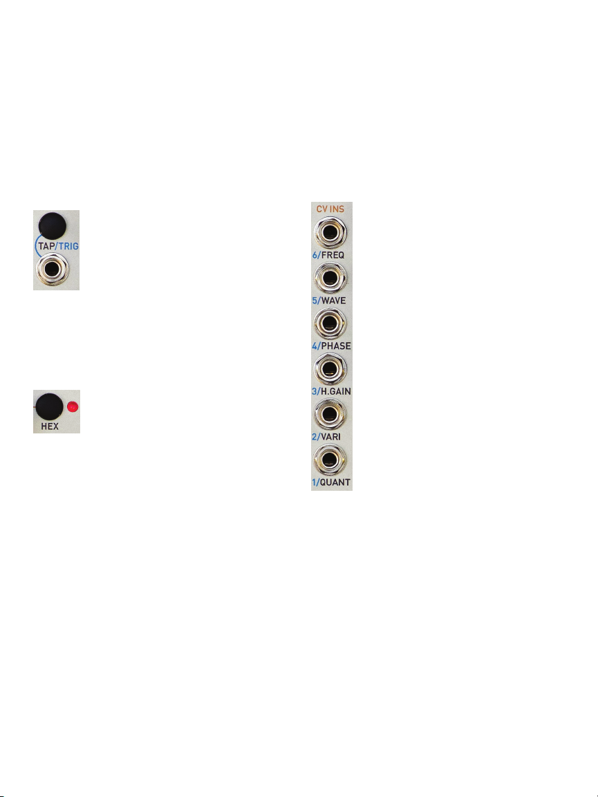
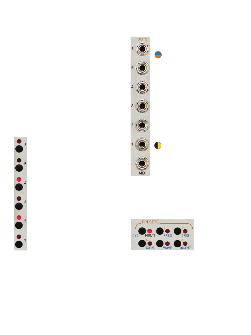
Channel Selectors and LEDs
The channel selector buttons are
used to select channels for editing, to
manually trigger individual channels,
and to solo or mute individual
channels.
The LEDs indicate the channels
selected for editing as well as
displaying triggers. When OPTION
is held or latched, the LEDs act as a
graphical output level viewer.
When editing HARM/SERIES, HARM#,
OCTAVE, QUANT, SEMI, or DC, the
LEDs (along with the Preset LEDs and
the HEX LED) will display the current
pot value as a temporary LED meter.
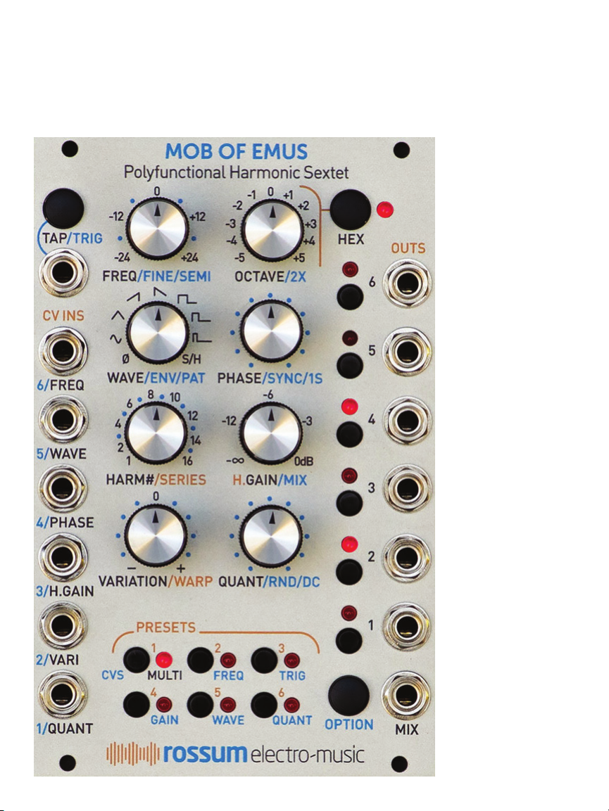
Outputs
Six individual channel outputs and a
summed Mix output.
NOTE: You’ll notice that the
individual channels are labeled
with #1 at the bottom and #6 at the
top. Given Mob of Emus’ various
“harmonic” functions, it makes sense
to treat the channels as harmonics,
with the lower frequencies at the
bottom and the progressively
higher frequencies towards the top.
Of course, you can set channel
frequencies to anything you like,
but if you’re using the “harmonic”
functions, maintaining the bottom-
to-top organization will tend to make
things conceptually clearer.
IMPORTANT NOTE: In order to
ensure precisely accurate CVs,
the impedance of Mob of Emus’
outputs is less than 1 Ohm. Because
of this, the outputs will not directly
drive headphones. If you would like
to monitor Mob of Emus’ outputs
when used at audio frequencies, first patch it
into an audio processing module like a VCA,
output module, filter, etc., and then monitor it
there.
Preset/CV Mode Selectors
Lets you load or
save one of 12
presets. Double-
click and hold
OPTION and
click to select
the CV Input Mode.
Power Down Behavior
Upon power down (including accidental
removal of power or a power failure), the
state of the module is saved and reloaded the
next time the module is powered up.