manuals.online logo
Brands
  1. Home
  2. •
  3. Brands
  4. •
  5. Rotary Lift
  6. •
  7. Lifting System
  8. •
  9. Rotary Lift 200 Series User manual

Rotary Lift 200 Series User manual

This manual suits for next models

3

Popular Lifting System manuals by other brands

probst SDH-H-15 operating instructions

probst

probst SDH-H-15 operating instructions

Bruno OUTDOOR ELITE CRE-2110E Operator's manual

Bruno

Bruno OUTDOOR ELITE CRE-2110E Operator's manual

matev FPS Mounting Assembly Installation Guide

matev

matev FPS Mounting Assembly Installation Guide

Vestil CYL-HLT Series instruction manual

Vestil

Vestil CYL-HLT Series instruction manual

Butts Tools BXS0002 operating instructions

Butts Tools

Butts Tools BXS0002 operating instructions

Safelift MoveAround MA60 Original instructions

Safelift

Safelift MoveAround MA60 Original instructions

Terex Genie Z452513A-48153 Service and repair manual

Terex

Terex Genie Z452513A-48153 Service and repair manual

Granberg InDIago 510 Operating and care instructions

Granberg

Granberg InDIago 510 Operating and care instructions

EUFAB Bike Lift operating instructions

EUFAB

EUFAB Bike Lift operating instructions

morse 82H-124 Operator's manual

morse

morse 82H-124 Operator's manual

Braun NL955 Series Operator's manual

Braun

Braun NL955 Series Operator's manual

Protekt AT 252 instruction manual

Protekt

Protekt AT 252 instruction manual

R. Beck Maschinenbau HS 600 operating manual

R. Beck Maschinenbau

R. Beck Maschinenbau HS 600 operating manual

Nova Technology International, LLC NAS Series quick start guide

Nova Technology International, LLC

Nova Technology International, LLC NAS Series quick start guide

Genie Z-60/34 Operator's manual

Genie

Genie Z-60/34 Operator's manual

Screen Technics INTERFIT Vertical Up Lift instructions

Screen Technics

Screen Technics INTERFIT Vertical Up Lift instructions

Drive DUPONT SAMERY Hermes user manual

Drive

Drive DUPONT SAMERY Hermes user manual

Custom Equipment Hy-Brid 3 Series MAINTENANCE & TROUBLESHOOTING MANUAL

Custom Equipment

Custom Equipment Hy-Brid 3 Series MAINTENANCE & TROUBLESHOOTING MANUAL

manuals.online logo
manuals.online logoBrands
  • About & Mission
  • Contact us
  • Privacy Policy
  • Terms and Conditions

Copyright 2025 Manuals.Online. All Rights Reserved.

I
N
S
T
A
L
L
A
T
I
O
N
I
N
S
T
R
U
C
T
I
O
N
S
I
N
S
T
A
L
L
A
T
I
O
N
I
N
S
T
R
U
C
T
I
O
N
S
IN20334
Revision C 11/03/2016
Rheinland
TUV
SPO65M(200 Series Lifts)
SPO65E(600 Series Lifts)
Standard Arms Capacity 6500 kg. (14,300 lbs.)
Sprinter Arms Capacity 5000 kg. (11,000 lbs.)
LP20074
© July 2006 by Rotary Lift. All rights reserved. CO6194.16
APPROACHAPPROACH
C
L
Wheel Spotting Dishes
SPO65M Series
SPO65E Series
489mm
1586mm
489mm
1586mm
4572mm Min.
To Nearest
Obstruction
4572mm Min.
To Nearest
Obstruction
4572mm Min.
To Nearest
Obstruction
4572mm Min.
To Nearest
Obstruction
90° 90°
(18) 3/4" Anchors
Alignment Notches
3937mm
2286mm Min. To
Nearest Obstruction
2286mm Min. To
Nearest Obstruction
864mm
711mm
152mm
864mm
711mm
152mm
Power Unit to
Passenger Side
FRONT
REAR
165mm from other
equipment typical
both sides
C
L
Wheel Spotting
Dishes
90°
(18) 3/4" Anchors
90°
Power Unit To
Driver Side
Alignment Notches
Front
Rear
3937mm Base Plate To Base Plate
3962mm Control Panel To Control Panel
Lift
Fig. 1
1. Lift Location: Use architects plan when available to
locate lift. Fig. 1 shows dimensions of a typical bay
layout.
2. Lift Height: See Fig. 4 for overall lift height of each
specific lift model. Add 25.4mm min. to overall height
to lowest obstruction.
WARNING
DO NOT install this lift in a pit or
depression due to fire or explosion risks.
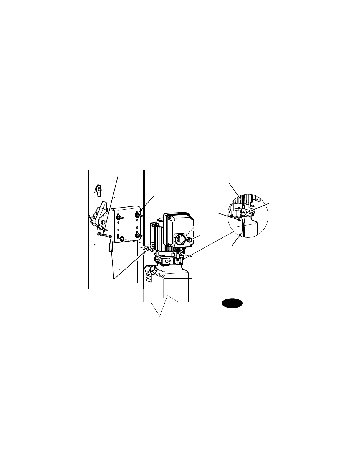
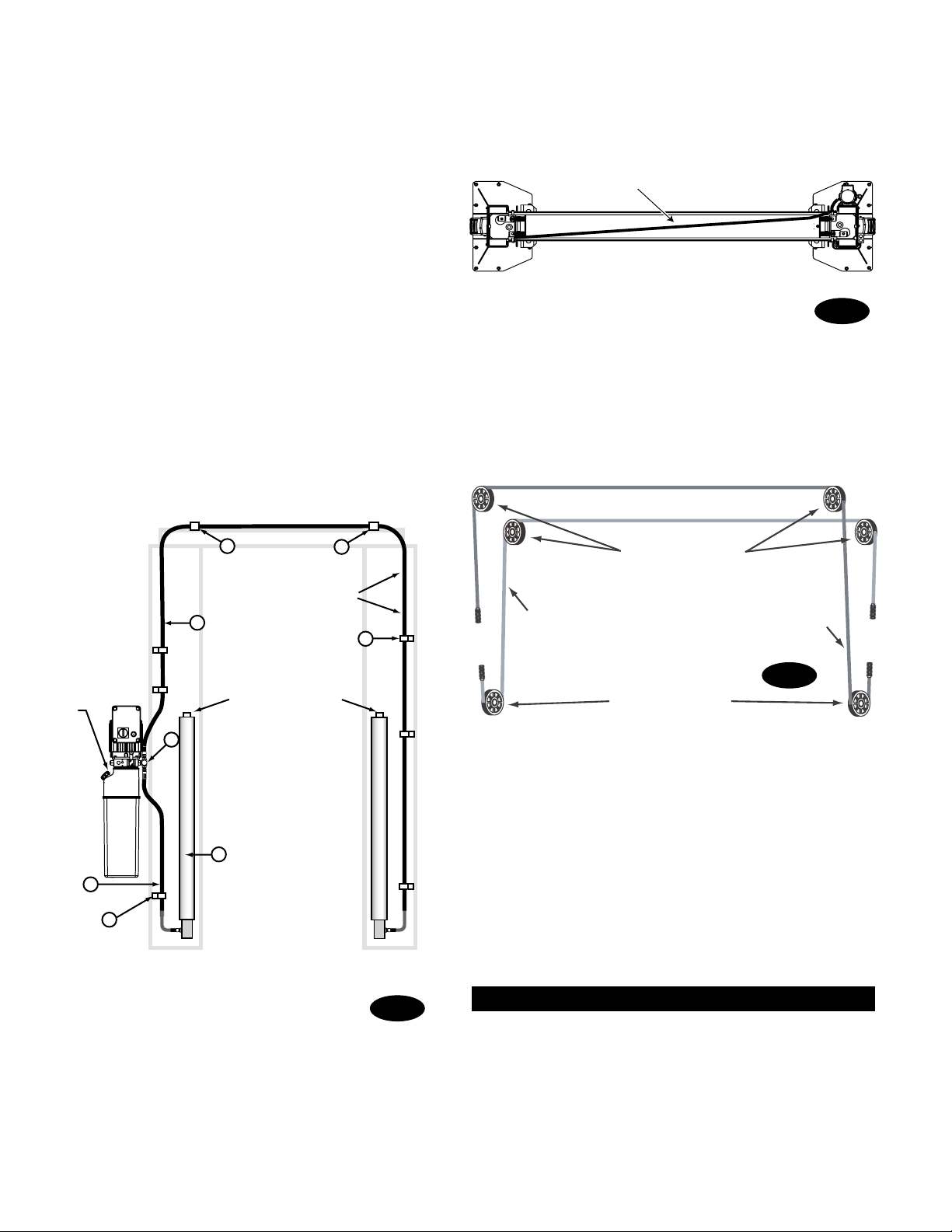
3. Lift Setting: Using a block and tackle (or similar
device that increases mechanical advantage), stand
the columns up. Position columns in bay using
dimensions shown in Fig.1. Place column with power
unit mounting bracket on vehicle passenger side of
lift. Both column base plate backs must be square
on center line of lift. Notches are cut into each base
plate to indicate center line of lift.
Use appropriate equipment to raise carriage to first
latch position. Be sure locking latch is securely
engaged.
A) Concrete Thickness & Hole Depth (220mm)
B) Edge Distance (120mm)
C) Hole Spacing (165mm)
4. Concrete and Anchoring: Concrete shall have a
compression strength of at least 20.68 N/mm² and a
minimum thickness of 108mm in order to achieve a
minimum anchor embedment of 83mm. When using
the standard supplied 3/4” x 5-1/2” lg. anchors, if the
top of the anchor exceeds 57mm above the floor
grade, you DO NOT have enough embedment.
Drill (18) 19mm dia., Fig. 2 holes in concrete floor using
holes in column base plate as a guide. See diagrams
for hole depth, hole spacing, and edge distance
requirements.
CAUTION DO NOT install on asphalt or other
similar unstable surfaces. Columns are supported only by
anchors in floor.
A
B
C
B
C
CC
Clean hole.
Run nut down just
below impact section
of bolt. Drive anchor
into hole until nut and
washer contact base.
Drill holes using
19mm carbide
tipped masonry
drill bit per
ANSI standard
B94.12.1977
115mm
Tighten nut with
Torque wrench to
203.4Nm.
57mm
82mm
115mm
Installation torque of 203.4Nm. is required for all anchor bolts.
Fig. 2
Fig. 3
NOTE: If more than 2 horse shoe shims are used at any of
the column anchor bolts, pack non-shrink grout under the
unsupported area of the column base. Insure shims are
held tightly between the baseplate and floor after torquing
anchors.
Shims
(12.7mm Max.)
Nut
Flat
Washer
Anchor
IMPORTANT Using the horse shoe shims provided,
shim each column base until each column is plumb, Fig.
3. If one column has to be elevated to match the plane
of the other column, full size base shim plates should be
used (Reference Shim Kit). Recheck columns for plumb.
Tighten anchor bolts to an installation torque of 203.4 Nm.
Shim thickness MUST NOT exceed 13mm when using the
140mm long anchors provided with the lift.
If anchors do not tighten to 203.4 Nm. installation torque,
replace concrete under each column base with a 1219mm
x 1219mm x 152mm thick 20.68 Nmm² minimum concrete
pad keyed under and flush with the top of existing floor.
Let concrete cure before installing lifts and anchors.
Adjustable
4572mm to
5029mm
Right Column
View From
Approach Side
Column Extension
Column
Column Tie
(2) 1/4"-20NC x 3/4" Lg. HHCS
(2) 1/4"-20NC Hex Nuts
(16) 3/8"-16NC x 3/8" Lg. HHCS
(1) 3/8" Star Washer used on
right side only.
(8) 3/8"-16NC x 1" Lg.
Flanged HHCS
3/8"-16NC x 1/2" Lg.
Flanged HHCS Extensions are adjustable in 152mm
increments from 4572mm to
5039mm for Standard models, and
from 4115mm to 4420mm for LC
models.
• All Star Washers are to be mounted
on the Right side column to ensure
grounding of overhead limit switch.
Star Washers are not needed when
mounting to Left side column. Notice
the column extension mounting, Fig. 4,
and overhead limit switch mounting
as well in Fig. 5.
IMPORTANT
Fig. 4
Star Washers
3/4" Spacer
1/4"-20NC x 2" Lg. HHCS
& Locknut
Overhead Switch
1.6mm Gap (2) 1/4"-20NC x 3/4" Lg.
HHCS
1/4"-20NC
Zinc Hex Nut
1/4"-20NC x 3/4" Lg.
External Tooth
Lockwasher
Fig. 5
5. Install column extensions to columns using (16) 3/8"-
16NC x 3/8" lg. Flanged HHCS, Fig. 4, and Column Ties
using (8) 3/8"-16NC x 1" Flanged HHCS, also Fig. 4.
Adjust column extensions plumb as required.
6. Mount switch assembly towards power unit column
as shown, Fig. 5, using (2) 1/4"-20NC x 3/4" lg. HHCS,
nuts and Star Washers. Insert 2” Hex bolt through
pivot hole in end of switch bar. Insert opposite end
(weighted end) of bar through slot in switch mount-
ing bracket. Then secure Hex bolt and switchbar to
overhead as shown, using 3/4" spacer and lock nut.
Tighten Hex bolt leaving 1.6mm gap between the spac-
er and the crosshead assembly.
Fig. 6
Crosshead Assembly
Star Washers
Column Extension
(16) 3/8"-16NC x 3/4" Lg.
HHCS & Flanged Locknuts
7. Install crosshead assembly to column extensions with
(16) 3/8"-16NC x 3/4" lg. HHCS, Flanged Locknuts and
Star Washers, Fig. 6.
Attention: For M series lifts proceed to page 7 Step 8.
5/16"-18NC x 1-1/2" HHCS
Vibration
Pad
Attach (2) 5/16"-18NC
Flanged Locknuts To
To p Bolts Just Far Enough
To Allow You To Hang The
Power unit On The Column Safely
Put Bolts Through
Bottom Of Power Unit Bracket
And Push Vibration Pads
Onto The Bolts
Keep Bottom Vibration Pads
Flush With The Ends Of The Bolts
This Will Aid In The Installation
Of The Power Unit
To The Column Extension
Do Not Put
Bottom Flanged Lock Nuts
On At This Time
These Will Have
To Be Attached
Through The Column Extension
Fill Breather Cap
Slip Top Tw o
Bolts Through
Key Hole Slots
Attach (2)5/16"-18NC
Flanged Locknuts To
The Bottom Two Bolts
After Pushing The Bolts
Through The Column
Hand Tighten
Tee Then
Tighten Hex Locknut
10-15 ft-lbs.
Fig. 7
Fig. 8
8. Unité d’alimentation de la série E: Attach vibration
pads and locknuts to bolts per Fig. 7. Enfoncer les 4 vis
en acier au carbone à tête hex. 5/16“-18NC x 1 - 1/2“ à
travers les trous de l‘unité d‘alimentation, fig. 7. Raccorder
les coussinets anti-vibration et les contre-écrous aux
boulons comme l‘indique la fig. 7. Installer et serrer à
la main le raccord en T sur la pompe jusqu‘à ce que le
joint torique ait une assise correcte, fig. 8. Continuer de
serrer le contre-écrou à 10-15 pieds-livres ou jusqu‘à ce
que l‘écrou et la rondelle se trouvent plaqués contre le
distributeur de pompe.
Remarque: Il se peut qu’il soit encore possible de faire
pivoter le raccord en T. Ceci est admissible à moins qu’il
n’y ait une infiltration sur le joint torique. Si c’est le cas,
serrer légèrement le contre-écrou.
Fig. 8a
CAUTION Si vous serrez le contre-écrou trop fort,
vous risquez de déchirer le joint torique ou de tordre le
filetage de la sortie du distributeur de pompe.
Accrocher l‘unité d‘alimentation sur l‘extension de colonne
côté conducteur, fig. 1. Enfoncer les deux boulons du
bas dans l‘étrier de l‘unité en les faisant passer à travers
l‘extension de colonne. Visser 2 contre-écrous à bride
5/16“-18NC sur les boulons. Serrer les quatre boulons sur
l‘étrier de l‘unité d‘alimentation en vérifiant qu‘il est fixé
à la colonne, fig. 8a. Accrocher l‘unité d‘alimentation sur
l‘extension de colonne côté conducteur, fig. 1. Enfoncer
les deux boulons du bas dans l‘étrier de l‘unité en les
faisant passer à travers l‘extension de colonne. Visser 2
contre-écrous à bride 5/16“-18NC sur les boulons. Serrer
les quatre boulons sur l‘étrier de l‘unité d‘alimentation en
vérifiant qu‘il est fixé à la colonne, fig. 8a.
Hose Routes Diagonally Across Overhead
1
2
3
4
5
FRONT 6
7
5
5
7
Hose runs down
approach side to
cylinder on left column.
Cylinder Bleeders
Hose runs through holes in
extensions, then through
holes in overhead.
Before Routing
Hydraulic Hose
Insert Rubber Grommet
Through Large Hole
In Column Next To
Tee Side Of Power Unit
Fill/Breather
Cap
ITEM QTY. DESCRIPTION
1 2 Hydraulic Cylinder
2 1 Power Unit Hose
3 1 Overhead Hose
4 1 Branch Tee
5 3 Hose Clips(5/8")
5 3 5/16"-18NC x 3/8” lg. PHMS
6 1 Hose Clips(1/2")
6 1 5/16"-18NC x 3/8” lg. PHMS
7 2 Hose Clips(5/8")
7 2 5/16"-18NC x 1/2” lg. PHMS
7 2 5/16"-18NC Nut
9. E Series Hoses: Before routing hoses insert rubber
grommet in column, Fig. 10. Clean adapters and hose.
Inspect all threads for damage and hose ends to be sure
they are crimped, Fig. 10a.
Flared Fittings Tightening Procedure
1. Screw the fittings together finger tight. Then, using
the proper size wrench, rotate the fitting 2-1/2 hex flats (1/3
of a revolution).
2. Back the fitting off one full turn.
3. Again tighten the fittings finger tight; then using a
wrench, rotate the fitting 2-1/2 hex flats (1/3 revolution).
This will complete the tightening procedure and develop a
pressure tight seal.
Adapter & Hose Installation
1. Install Pc. (2) with hose clamps, on power unit column
side connecting it to the cylinder (1) first.
2. Install Pc. (3) with hose clamps starting at left column
cylinder (5) and working toward the right column.
All excess hose should be at bends & inside overhead
assembly.
3. Install Pc. (4) into power unit.
4. Connect Pc. (2) & Pc. (3) to Tee (4).
Branch Te e
Power Unit
(Short) Hose
Overhead
Hose
Fig. 10
Fig. 10b
NOTE: Route Power Unit hose inside columns using slots
provided at column base, Fig. 10b. Route Overhead Hose in
column channel on outside of column, Fig. 10b. Overhead
hose goes through holes beside sheaves in the overhead
weldment, Fig. 10b.
Oil Filling: Use Dexron III ATF, or Hydraulic Fluid that
meets ISO 32 specifications. Remove fill-breather cap,
Fig. 10. Add fluid until it reaches fill line on tank. System
capacity is (14) quarts. Replace fill-breather cap.
Fig. 10a
Attention: For E series lifts proceed to page 8 Step 10.
Fig. 11
8. M Series Power Unit: First install (1) Star Washer
onto one of the (4) 5/16" 18NC x 1-1/2" bolts. This is
very important for grounding. Put (4) 5/16" 18NC x
1-1/2" lg. bolts thru holes in power unit bracket using
push-nuts to hold in place. With the motor being the
heaviest part of the unit, two people lift the unit, each
with one hand supporting the motor. Position the unit
on the bolts with one person supporting the power
unit while the other installs lock washers and nuts.
Install and tighten Hydraulic Hose Adapter to pump.
Then install and tighten Tee, and connect supply
hoses to Tee, Fig. 11.
9. M Series Hoses: Clean adapters and hose. Inspect all
threads for damage and hose ends to be sure they are
crimped, Fig. 11.
Flared Fittings Tightening Procedure
1. Screw the fittings together finger tight. Then, using
the proper size wrench, rotate the fitting 2-1/2 hex flats
(1/3 of a revolution).
2. Back the fitting off one full turn.
3. Again tighten the fittings finger tight; then using
a wrench, rotate the fitting 2-1/2 hex flats (1/3
revolution). This will complete the tightening
procedure and develop a pressure tight seal.
On one bolt, place
(2)5/16" Star Washers
Push nuts hold bolts to brackets.
Use (4)5/16"-18NC
x1-1/2" lg. HHCS
and Nuts
Raise
Switch
Disconnect
Switch
Lowering
Valve
Fill-Breather Cap
Power Unit (Short) Hose
Crimped Hose
Sleeve (Typical)
Branch Tee
Overhead Hose
1st Cable
2nd Cable
Upper Sheaves
Lower Sheaves
Abb. 13
Cylinder bleeders
1
2
3
4
5
66
FRONT
Hose runs down
approach side to
cylinder on left
column.
HOSE ROUTING FOR SPO65M SERIES
ITEM QTY. DESCRIPTION
1 2 Hydraulic Cylinder
2 1 Power Unit Hose
3 1 Overhead Hose
4 1 BranchTee
5 6 Hose Clips
6 3/8-16NC x 3/4” Carriage Bolts
6 3/8-16NC Flanged Locknuts
6 4 Hose Clips
4 3/8"-16NC x 3/4" HHCS
4 3/8"-16NC Flanged Locknuts
7 2 Mechanical Lift Hole Plug
Fill-Breather
Cap
7
M Series Adapter & Hose Installation
1. Install item (2) with hose clamps, on power unit column
side connecting it to the cylinder (1) first.
2. Install item (3) with hose clamps starting at left column
cylinder (5) and working toward the right column. All
excess hose should be at bends & inside overhead
assembly.
3. Install item (4) into power unit.
4. Connect item (2) & item (3) to Tee (4).
Abb. 12
Hose Routes Diagonally Across Overhead
NOTE: Route Power Unit hose inside columns using slots
provided at column base, Fig. 12. Route Overhead Hose in
column channel on outside of column, Fig. 12. Overhead
hose goes over top end of overhead assembly, Fig. 12 and
Fig. 12a.
Abb. 12a
10. Equalizer Cables: Fig. 13 describes general cable ar-
rangements. It is easier to tie-off lower studs first.
A) Run cable stud up through the lower tie-off plate,
and/or bracket(s), and/or spacer(s) depending on the
lift model, Fig. 14.
B) Push cable up until stud is above top of carriage Fig.
10.
C) Run nylon insert locknut onto studs so that 12mm
extends out from locknut Fig. 14.
D) Pull cables back down through carriage Fig. 14.
E) Run cable overhead and tie-off top studs and torque to
about 11.3J., see Fig. 13 & Fig. 14.
Attention: For E series lifts proceed to page 12 Step 11.
For 4724mm height lift with 11,989mm cable, or
4115mm height lift with 10,770mm long cable.
Use pattern 3.
For 4877mm height lift with 11,989mm cable or fo
r
4267mm height lift with 10,770mm long cable, both
use pattern two. Has 305mm spacer provided.
For 4572mm height carriges use pattern four
with 11,989mm cable. Has 305mm spacer
provided.
For 5029mm height with 11,989mm long cable or
for 4420mm height with 10,770mm long cable, both
use pattern one.
4
3
1
2
Upper Cable Tie Off
3/4" Nylon Insert Locknut
610mm
Upper Cable Tie Off
3/4" Nylon Insert Locknut
610mm
305mm
Upper Cable Tie Off
3/4" Nylon Insert Locknut.
305mm
Spacer
Upper Cable Tie Off
3/4" Nylon insert locknut.
305mm
Spacer
Fig. 14
Controllo gancio
d’arresto Piastra
1/4"-20NC x 1-3/4"
HHCS & Nylon Nut
Perno della
forcella & anelli
di ritenzione
Fo
rcella cilindro aria
Distanziale di
ammor
tizzazione
Cilindro aria
Staffa
Gancio di
arresto
Fig. 15
11. For M Series Locking Latch & Air Cylinders:
A) To install cylinder, first slip dampening spacer over rod
with rod in retracted position, Fig. 15.
B) Put locknut on threaded shaft and run it down to the
dampening spacer.
C) Let rod extend and thread locknut down 1-1/2 more
turns.
D) Screw Bracket Clevis onto shaft, position, and tighten
locknut securely, Fig. 15.
E) Attach air cylinder clevis to latch control plate with
clevis pin and retaining rings, Fig 15. Attach bottom
of air cylinder to air cylinder bracket with 1/4" x 1-3/4"
HHCS and nylon nut, Fig. 15. Repeat procedure for
other locking latch.
F) Mount lowering switch and bracket to column using
(2) 5/16"-18NC x 3/8" lg. PHMS, Fig. 15a.
G) Install air lines from main air supply (with filter) to
lowering switch. Install air line from lowering switch
to union tee then to the right column air cylinder.
H) Install air line from union tee to left column air cylin-
der. Figs.15b and 16.
Note: Cut provided tubing with sharp blade to length as
required. Tubing must be cut square with no burrs. To
assemble air line tubing into fitting, use firm, manual pres-
sure to push tubing into fitting until it bottoms, see below.
If removal of the air line tubing from the fitting is ever
required, hold Push Sleeve in (against fitting) and at the
same time, pull out on tubing.
Locking Latch Engagement Test:
A) Raise carriages past the first latch position and then
lower onto latches.
B) Check that the latches have fully engaged when the
release switch is not depressed.
C) Raise carriages fully off latches. Now depress release
switch and check that the latches have fully disen-
gaged.
D) Check for air leaks, make necessary adjustments or
repairs if required.
E) Install latch covers with 5/16"-18NC x 3/8" lg. BHCS, Fig.
17.
Attention: For M series lifts proceed to page 24 Step 12.