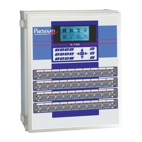
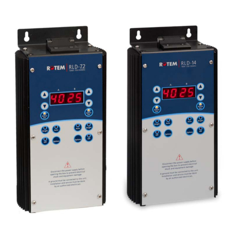
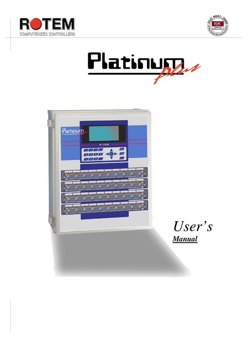
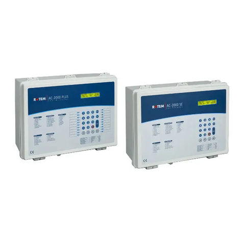
Rotem platinum junior xl User manual

Platinum Controllers
Version 4.11
User Manual (Precision)
P/N: 110431

Warranty & Limitation of Liability
1. ROTEM warrants that the product shall be free of defects in materials or workmanship and will
conform to the technical specification for a period of 1 (one) year from the date of initial
installation on site (the "warranty period").
2. ROTEM warrants that during said warranty period, any item/items or part/parts of equipment
found defective with respect to materials or workmanship or which do not conform to the technical
specification shall be repaired or replaced (at ROTEM's sole discretion), free of charge.
3. During the warranty period, in the event of an alleged defect, authorized resellers in relevant
regions should be notified as soon as possible from the date of noticing the said defect, but no
longer than thirty (30) days from such a discovery. The report shall include (1) a short description
of the defects noticed (2) type of card / component and its matching serial number.
4. ROTEM's sole liability under this warranty is the repair or replacement of the defective item of
product.
5. Load cells are not covered by ROTEM’s warranty.
Conditions and Limitations
1. ROTEM will not be responsible for any labor costs or expenses associated with replacement of
defective items or other parts of the product or repair.
2. This warranty shall not cover: (i) product or part therein which has been modified (without prior
written approval of ROTEM), or (ii) product or part therein which has not handled or installed by
an authorized reseller of ROTEM or (iii) product or part therein which has either handled or
installed not in strict accordance with ROTEM's instructions, (iv) products which were used for
function other than agriculture industry.
3. This warranty will not apply in the following cases: (i) if all components of the product are not
originally supplied by ROTEM (ii) the defect is the result of an act of nature, lighting strikes,
electrical power surge or interruption of electricity (iii) the defect is the result of accident, misuse,
abuse, alteration, neglect, improper or unauthorized maintenance or repair.
ROTEM warns and alerts all users that the Product is inherently complex and may not be
completely free of errors. ROTEM's products are designed and manufactured to provide reliable
operation. Strict tests and quality control procedures are applied to every product. However, the
possibility that something may fail beyond our control exists. Since these products are designed
to operate climate control and other systems in confined livestock environments, where failure
may cause severe damage, the user should provide adequate backup and alarm systems. These
are to operate critical systems even in case of a ROTEM system failure. Neglecting to provide
such a backup will be regarded as the user’s willingness to accept the risk of loss, injury and
financial damage.
In no event will ROTEM be liable to a user or any third party for any direct, indirect, special,
consequential or incidental damages, including but not limited to any damage or injury to
business earnings, lost profits or goodwill, personal injury, costs of delay, any failure of delivery,
costs of lost or damaged data or documentation, lost or damaged products or goods, lost sales,
lost orders, lost income.
Except for the above express warranty, ROTEM makes no other warranties, express or implied,
relating to the products. ROTEM disclaims and excludes the implied warranties of merchantability
and fitness for a particular purpose. No person is authorized to make any other warranty or
representation concerning the performance of the products other than as provided by ROTEM.
Software Version: 4.11
Document Version: 1.2

Table of Contents
1 Front Matter .................................................................................................. 7
1.1 Introduction .................................................................................................................. 7
1.2 Conventions .................................................................................................................. 7
1.3 Contact Information ...................................................................................................... 7
1.4 Document Information .................................................................................................. 7
2 Introduction to Precision Mode................................................................... 8
2.1 Front Panel.................................................................................................................... 8
2.1.1 Keypad ...................................................................................................................... 9
2.1.2 Relay Switches .......................................................................................................... 9
2.1.3 Hot Screens ............................................................................................................. 10
2.1.4 Standard Display ..................................................................................................... 11
2.1.5 Main Menu Icons ..................................................................................................... 13
2.2 Operating Modes ........................................................................................................ 13
3 Control Menu .............................................................................................. 14
3.1 Temperature Curve ..................................................................................................... 14
3.1.1 Temperature Curve Help | Set Definitions ................................................................ 15
3.1.2 Radiant Heaters Help | Set Definitions ..................................................................... 16
3.1.3 Variable Heater Help | Set Definitions ...................................................................... 17
3.2 Introduction to Humidity and CO2 Treatment ........................................................... 18
3.3 Humidity Treatment .................................................................................................... 18
3.3.1 Humidity Treatment Help | Set Definitions ................................................................ 19
3.4 CO2 Treatment ............................................................................................................ 20
3.4.1 CO2 Treatment Help | Set Definitions ...................................................................... 20
3.5 Min/Max Level ............................................................................................................. 21
3.5.1 By Day and By Days Curve ...................................................................................... 21
3.5.2 By Time ................................................................................................................... 22
3.5.3 Day Soft Min. ........................................................................................................... 22
3.5.4 By Weight ................................................................................................................ 23
3.6 Static Pressure ........................................................................................................... 25
3.6.1 Disabling the Static Pressure Sensor ....................................................................... 26
3.6.2 Static Pressure Help | Set Definitions ....................................................................... 26
3.7 Control Mode .............................................................................................................. 27
3.8 System Parameters .................................................................................................... 27
4 Device Menu ............................................................................................... 29
4.1 Levels of Ventilation ................................................................................................... 30
4.1.1 Levels of Ventilation Help | Set Definitions ............................................................... 31
4.2 Variable Speed Fan Levels ......................................................................................... 32
4.3 Vent & Curtain Levels ................................................................................................. 32
4.3.1 Vent & Curtain Levels Help | Set Definitions ............................................................. 33
4.4 Stir Fan Levels ............................................................................................................ 34
4.5 Stir Fan Program ........................................................................................................ 35
4.5.1 Stir Fan Program Help | Set Definitions .................................................................... 35
4.6 Cool Pad...................................................................................................................... 36
4.6.1 Cool Pad Help | Set Definitions ................................................................................ 37
4.7 Foggers ....................................................................................................................... 38
4.7.1 Foggers Help | Set Definitions .................................................................................. 38
4.8 Light ............................................................................................................................ 39

4.8.1 Light Help | Set Definitions ....................................................................................... 40
4.9 Water & Feed .............................................................................................................. 41
4.9.1 Water and Feed Help | Set Definitions ..................................................................... 42
4.10 Extra Systems ............................................................................................................. 43
4.11 Emergency Setting ..................................................................................................... 43
4.11.1 Emergency Setting Help | Set Definitions ................................................................. 44
4.12 Water on Demand ....................................................................................................... 45
4.13 Feeding Plan ............................................................................................................... 45
4.13.1 Feed Plan Help | Set Definitions............................................................................... 46
4.13.2 Feed Plan Hot Screen.............................................................................................. 47
5 Manage Menu ............................................................................................. 48
5.1 Bird Inventory ............................................................................................................. 48
5.2 Feed Inventory ............................................................................................................ 48
5.2.1 Feed Inventory Help | Set Definitions ....................................................................... 49
5.3 Time & Date................................................................................................................. 49
5.4 Growth Day & Flock .................................................................................................... 50
5.5 Alarm Setting .............................................................................................................. 50
5.5.1 Alarm Setting Help | Set Definitions.......................................................................... 51
5.6 Alarm Reset ................................................................................................................ 52
5.7 Fail Safe Setting .......................................................................................................... 53
5.8 Password .................................................................................................................... 53
5.9 Relay Current .............................................................................................................. 54
6 Scale Menu ................................................................................................. 55
6.1 Scale Layout ............................................................................................................... 55
6.2 General Settings ......................................................................................................... 55
6.2.1 General Settings Help | Set Definitions..................................................................... 56
6.3 Bird Scale Setting ....................................................................................................... 56
6.4 Feed Bin Setting ......................................................................................................... 57
6.5 Bird Curve ................................................................................................................... 57
6.6 History ......................................................................................................................... 58
6.7 Feed Conversion ........................................................................................................ 58
6.8 Test ............................................................................................................................. 59
6.9 Calibration .................................................................................................................. 59
6.9.1 Scale Calibration ..................................................................................................... 59
6.9.2 Feed Bin Calibration ................................................................................................ 60
7 History Menu .............................................................................................. 61
7.1 Temperature ................................................................................................................ 61
7.2 Humidity ...................................................................................................................... 61
7.3 CO2 ............................................................................................................................. 61
7.4 Water ........................................................................................................................... 62
7.5 Feed............................................................................................................................. 62
7.6 Mortality ...................................................................................................................... 62
7.7 Heaters ........................................................................................................................ 62
7.8 Radiant Heaters .......................................................................................................... 62
7.9 Alarms ......................................................................................................................... 62
7.10 Table of Events ........................................................................................................... 62
7.11 History View ................................................................................................................ 63
7.12 Power Consumption ................................................................................................... 63

8 Test Menu ................................................................................................... 64
8.1 Switches & Relays ...................................................................................................... 64
8.2 Switches & Relays Extension .................................................................................... 65
8.3 Alarm ........................................................................................................................... 65
8.4 Analog Sensors .......................................................................................................... 65
8.5 Digital Sensors ........................................................................................................... 66
8.6 Analog Output............................................................................................................. 66
8.7 Static Pressure ........................................................................................................... 66
8.8 Communication .......................................................................................................... 67
8.9 Hardware Checklist .................................................................................................... 67
8.10 Emergency Status ...................................................................................................... 67
9 Service Menu .............................................................................................. 68
9.1 Temperature Calibration ............................................................................................ 68
9.2 Humidity Calibration ................................................................................................... 69
9.3 CO2 Sensor ................................................................................................................. 69
9.4 Static Pressure Calibration ........................................................................................ 70
9.5 Light Sensor Calibration ............................................................................................ 71
9.6 Feed Calibration ......................................................................................................... 71
9.7 Water Calibration ........................................................................................................ 72
9.8 Vent Calibration .......................................................................................................... 72
9.9 Nipple Flushing ........................................................................................................... 73
9.9.1 Nipple Flushing Help | Set Definitions ...................................................................... 73
9.10 Feeders & Drinkers ..................................................................................................... 74
9.10.1 Feeders & Drinkers Help | Set Definitions ................................................................ 74
9.11 Save Settings to Plug ................................................................................................. 75
9.12 Read from Plug ........................................................................................................... 75
9.13 Current Sense Relay Calibration................................................................................ 76
10 Install Menu ................................................................................................ 78
10.1 Setup ........................................................................................................................... 78
10.2 Relay Layout ............................................................................................................... 79
10.2.1 Output Function List ................................................................................................. 79
10.2.2 Relay Layout – Help | Set Definitions ....................................................................... 80
10.3 Analog Sensors .......................................................................................................... 81
10.4 Digital Sensors ........................................................................................................... 81
10.5 Analog Output............................................................................................................. 82
10.6 Curtain Setup .............................................................................................................. 82
10.7 Temperature Definition ............................................................................................... 82
10.8 Fan Air Capacity ......................................................................................................... 83
10.9 House Dimensions ..................................................................................................... 84
10.10 Communication .......................................................................................................... 84
11 Appendix A: Output Data ........................................................................... 85
12 Appendix B: Breeder Setup ....................................................................... 88
12.1 Breeder Mode Cold Start ............................................................................................ 88
12.2 Breeder Setup ............................................................................................................. 88
12.3 Breeder Mode Water and Feed Ventilation ................................................................ 90
12.4 Breeder History........................................................................................................... 90
12.5 Breeder Mode Hot Screen .......................................................................................... 90
13 Appendix C: Feeder Setup ........................................................................ 91


7 Platinum | 4.11
1 FRONT MATTER
This section includes information on the manual and general information.
1.1 Introduction
Rotem manuals provide easy-to-use information regarding the installation, operation, long/short term
planning and parts listing (this manual may not deal with all of the above subjects). The table of
contents is an outline of the relevant information in this manual.
Read this manual before operating your Rotem product. Using this equipment for any other purpose or
in a way not within the operating recommendations specified in this manual will void the warranty and
may cause personal injury.
If you have any questions or comments regarding your product, please contact your local Rotem dealer.
1.2 Conventions
NOTE: Notes provide important details regarding specific procedures.
CAUTION Cautions alert you to potential damage to the controller if the procedures are not
followed carefully.
WARNING! Warnings alert you to potentially hazardous situations that, if not avoided, could
result in death or personal injury.
This symbol means that certain functions must be defined before a screen can be used.
1.3 Contact Information
Rotem Control and Management
Email: supp[email protected]m URL: www.rotem.com
1.4 Document Information
Revision History
Rev Level /
Date
Section Affected Description
1.0 / Nov 2013 Release document
1.1 / Sept 2014 3.2 – 3.5 Update to 4.10
1.2 / Mar 2015 4.11
© 2011 Rotem Corp.
All rights reserved.
Document Number: 110431 Revision Number: 1.2
No part of this publication may be reproduced, stored in an automated data file or made public in any
form or by any means, whether electronic, mechanical, by photocopying, recording or in any other
manner without prior written permission of the publisher.
Rotem will not accept responsibility for damage resulting from the use of this manual. Rotem also
reserves the right to make changes and improvements to its products and/or the associated
documentation without prior notice.

Platinum | 4.11 8
2 INTRODUCTION TO PRECISION MODE
This document describes the Platinum Precision Mode operation. For greater simplicity and ease of
use, you can opt to use the Standard Mode; documentation is provided in the Standard Mode manual.
Computerized Electronic Controllers such as the Platinum advance the producer’s ability to grow high
quality poultry by accurately controlling the environment. Instead of struggling with individual
thermostats for heat zones and ventilation, Platinum brings them all together into one convenient place
with great accuracy. In Precision Mode, the Platinum optimizes and precisely applies your equipment
and energy sources to most benefit from the accuracy of your computer and sensors.
Where Simplicity and Ease of Use are important benefits of Standard Mode, Features and Precise
Application characterize Precision Mode. The Platinum coordinates your ventilation equipment in
precise levels of ventilation to provide the optimal fresh air balanced with heating costs. The light and
feed clocks provide additional channels for greater capability. Besides advanced Cooling Pad methods,
you benefit from superior stir fan programs to recover ceiling heat and other features. Precision Mode’s
additional features enable you to improve your profitability significantly.
Platinum provides a variety of management and history utilities. You can choose from simple overviews,
or fully detailed by the minute records of minimum, maximum and average temperatures for each
individual sensor. The unique Table of Events records the moment of every significant action taken by
the Platinum and, optionally, its operator.
Communication software is available to customers who wish to access their Platinum controllers locally
or remotely at Rotem’s website, www.rotem.com. Rotem provides technical support on the website, as
well as through the large dealer and agent network.
• Front Panel, page 8
• Operating Modes, page 13
2.1 Front Panel
Figure 4 shows the Platinum Junior XL front panel and its elements.
Figure 1: Platinum Junior XL Front Panel
The following sections detail the front panel elements.

9 Platinum | 4.11
2.1.1 Keypad
Enter main menu, also acts as "ESC" or "Back" keys
Access help screens and graphs
Erase typing mistakes
Enter menus, values, open windows
Scroll up, down, left and right
Enter values, select options and make selections
Toggle between positive and negative values and mark check boxes
.
2.1.2 Relay Switches
Figure 2: Standard Relay Switches
Figure 5 illustrates a row of standard relay switches. Set each relay to:
• On: Always on
• Off: Always off
• Auto: The relay operates according to its set parameters.
Figure 3: Emergency Relay Switches

Platinum | 4.11 10
Figure 4: Winch Switches
2.1.3 Hot Screens
Many of the keys serve as shortcuts. Here are the main ones:
Software version
Return to standard main screen
Temperature, Humidity Status, and Wind Chill Temperature
Curve Status
Curtain Position
Bird Scale and Feed Bin Status
Light Status
Analog Output Status
Lock password protected controller
Scan through Hot Screens for five seconds each
Air Status (refer to Weight Hot Screen, page 25 for details on this screen)
Feed Scale Status (refer to Feed Plan Hot Screen, page 47)
NOTE: Increase/Decrease Offset from Temperature Setting from the Standard display only (hold both
keys) – defined in the TEMPERATURE CURVE HELP | SET

11 Platinum | 4.11
NOTE: If two humidity sensors are installed, Hot Screen 2 displays their average.
Increase/ decrease offset from temperature setting from the standard display only (hold
both keys) – defined in the TEMPERATURE CURVE HELP | SET
2.1.4 Standard Display
The main screen consists of the following parts.
1. Displays individual sensor readings. Temperature sensors marked with dark squares form the
current average temperature.
o Filled square: Indicates the sensor participates in the average calculation.
o Empty square: Indicates the sensor does not participate in the average calculation.
NOTE: Go to Table 3: Sensor Readings page 85, to view all the possible sensors.
SENSORS
AV. TEMP.
ACTIVE
Temp1
37.9°
27.5°
Heat
1
Temp2
16.2°
Heat. Hi
1
Temp3
28.2°
STATUS
Tun. Fan
E. Tmp1
28.8°
08:53:06
Exh. Fan
E. Tmp2
28.4°
Day: 2
Stir
Press.
23
Set:
25.0
Cool P.
Out T.
23.9°
Level:
3
Fogger
Hum. In
58.7%
Min.
Vent
Curt. 1
100%
Hum. Out
61.9%
FanOff:
176
Curt. 2
100%
Weight
0.000
Feeder
Weights
0
Auger
4 MESSAGES
Valve
(2) Low Feed At Bin 2
Alarm
SENSORS
Temp1
37.9°
Temp2
16.2°
Temp3
28.2°
E. Tmp1
28.8°
E. Tmp2
28.4°
Press.
23
Out T.
23.9°
Hum. In
58.7%
Hum. Out
61.9%
Weight
0.000
Weights
0

Platinum | 4.11 12
2. Reports the current average temperature. This example is in Celsius, but yours may be in
Fahrenheit.
3. Displays the output relay list. The filled black boxes indicate active outputs. Controller also
informs the position of inlets and curtains, as well as the number of operating heaters or fans.
NOTE: Go to Table 4: Output List (Active), page 85 to view all the available readings (ACTIVE).
NOTE: The ACTIVE screen shows rectangular markers by the outputs. Filled rectangles indicate
operating outputs; empty rectangles indicate outputs that are off.
4. Status Window provides important general information such as the time and ventilation mode.
EXAMPLE
NOTE: Go to Table 3: Sensor Readings, page 85 to view all the available readings.
5. Displays important messages/alarms. The title bar displays the number of important messages,
and if there are several messages, they each appear in turn.
AV. TEMP
27.5°
ACTIVE
Heat
1
Heat. Hi
1
Tun. Fan
Exh. Fan
Stir
Cool P.
Fogger
Curt. 1
100%
Curt. 2
100%
Feeder
Auger
Valve
STATUS
08:53:06
Day: 2
Set:
25.0
Level:
3
Min.
Vent
FanOff:
176
4 MESSAGES
(2) Low Feed At Bin 2
Temp set to
Time
Controller State
Growth day
Current level of ventilation
Time until cycle ends operation

13 Platinum | 4.11
2.1.5 Main Menu Icons
1. To enter the Main Menu screen, press Menu.
2. To select an option, press Enter.
2.2 Operating Modes
Platinum Controllers (Version 4.11) support two operating modes, Broiler and Breeder. Almost all Broiler
and Breeder functions are exactly the same. Functions which are specific to the Breeder Mode are
detailed in Appendix B: breeder setup, page 88.
1. If connected to a power source, disconnect the cord.
2. Apply power while pressing (and holding down) Delete.
3. In the screen that appears select YES.
4. In the screen that appears select PRECISION.
5. In the screen that appears select BROILER.
NOTE: To change to Breeder Mode, refer to Breeder Mode Cold Start, page 88.

Platinum | 4.11 14
3 CONTROL MENU
The following sections detail the following functions:
• Temperature Curve, page 14
• Humidity Treatment, page 18
• CO2 Treatment, page 20
• Min/Max Level, page 21
• Static Pressure, page25
• Control Mode, page 27
• System Parameters, page 27
3.1 Temperature Curve
This screen sets the temperature targets according to the bird age.
1. In Install > Analog Sensors (refer to Analog Sensors, page 81), designate the required number
of sensors as temperature sensors. When using more than one sensor, Platinum begins
treatments based on the average.
2. If required, go to Service > Temperature Calibration, calibrate the sensors (refer to
Temperature Calibration, page 68).
3. In Install > Temperature Definition (refer to Temperature Definition, page 82), assign specific
sensors brood setups, heater zones, and devices. If a zone does not have an assigned sensors,
calculations are based on the current average temperature.
4. In Control > Temperature Curve, define the required target temperature curve
o Set up to 20 lines, 999 growth days. When a curve is not required (for example when
growing layers), enter temperatures in the first line only.
o Define:
Day: Sets growth day. You can program negative growth days up to -2 for
pre-warming. To enter a negative growth day, type the day number followed
by the ± key.
Target: Set the desired temperature.
Heat: Set the temperature to stop heat.
Tunnel: Set the temperature for Tunnel ventilation to begin.
Alarm Low & High: Set average temperature alarm limits. See Manage |
Alarm Settings for zone alarm settings.
5. If required set the:
o Temperature Curve Help | Set Definitions, page 15
CONTROL
1. TEMPERATURE CURVE
2. HUMIDITY TREATMENT
3. CO2 TREATMENT
4. MIN/MAX LEVEL
5. STATIC PRESSURE
6. CONTROL MODE
7. SYSTEM PARAMETERS
8. EGG ROOM
TEMPERATURE CURVE
Day
Target
Heat
Tunnel
Alarm
Low
High
1
2
3
7
15
21
28
35
42
48
89.0
89.0
87.0
84.0
82.0
79.0
76.0
72.0
70.0
68.0
89.0
89.0
87.0
83.0
81.0
78.0
74.0
70.0
68.0
66.0
100.0
99.0
97.0
91.0
89.0
86.0
81.0
77.0
75.0
73.0
84.0
84.0
82.0
80.0
78.0
75.0
71.0
67.0
63.0
60.0
102.0
102.0
95.0
95.0
93.0
90.0
87.0
84.0
83.0
83.0

15 Platinum | 4.11
o Radiant Heaters Help | Set Definitions, page 16
o Variable Heater Help | Set Definitions, page 17
3.1.1 Temperature Curve Help | Set Definitions
While viewing the Temperature Curve menu: Press HELP, select SET, and press ENTER.
• Temperature Curve Offset: Adjusts all temperature curves by this amount. You can use this
to temporarily adjust all temperatures up or down for special circumstances. The curve
appears in the Status Window, and you can use the ENTER and Up or ENTER and Down
hot key combinations to change the offset.
• Set Temp. Change Reminder (Diff): Sets the change in set temperature that triggers a
reminder for you to set backup thermostats. Often producers forget to set backup thermostats
as their birds grow from baby chicks to market age, so the Platinum reminds you. When you
press Enter to acknowledge the reminder, the Platinum logs it in the Table of Events.
• Target Temp. Band: The size of the target temperature zone. This "Happy Zone” is between
Target Temperature and (Target Temperature + Band).
• Heater Temp. Band: Heaters turn on at ‘Band’ degrees below Heat, and turn off at the Heat
Temperature.
NOTE: Heaters operate at minimum level only; however, Radiant Heaters can operate at any
temperature or level below Tunnel.
• Cool Down Factor (%): Minimum percentage correction towards target during each increase
ventilation level delay. If average temperature does not improve by this amount, the Platinum
increases ventilation by one level.
• Cool Down Fast Response (Deg.): Set a limit to the maximum degrees per minute of
cooling. If Average Temperature drops more than this in one minute, the Platinum decreases
ventilation one level to avoid overshooting.
NOTE: Avoid making this parameter too small or the normal temperature variation caused by timer
fans reduces the ventilation level.
• Min Vent Below Heat Temp By: Tells controller to go directly to Min Level in some cases.
Select from the following choices:
o None: Operate by the normal level decrease time delay rule.
o Zone: Go directly to minimum level if any active temperature sensor reaches heat
temperature.
o Avg.: Go directly to minimum level if the average temperature reaches heat
temperature.
• Non Brood Area Diff. From Heat: Set differential temperature for non-brood heaters. You
normally use this to set temperatures in unoccupied areas.
NOTE: When set at -99° F the heaters are effectively disabled, since it will probably never go to 99º F
below the heater temperature. Putting this parameter at 0º sets the non-brood areas to the
heater temperature.
SYSTEM PARAMETERS
TEMPERATURE CURVE
Temperature Curve Offset
Set Temp. Change Reminder (Diff)
Target Temp. Band
Heater Temp. Band
Cool Down Factor (%)
Cool Down Fast Response (Deg.)
Min Vent Below Heat Temp By:
Non Brood Area Diff. From Heat
0.0
3.0
1.5
1.0
15
3.0
ZONE
-3.0

Platinum | 4.11 16
3.1.2 Radiant Heaters Help | Set Definitions
To configure the radiant heaters:
1. In Installation > Relay Layout define at least one relay as a radiant heater (Relay Layout,
page 79).
2. Configure the following parameters:
o Radiant Low – Differential from Heat Set: Set degree of difference from Heat for
LOW Radiant Heaters to begin working. This differential can be positive or negative.
(default: 2.0)
o Radiant High – Differential (Below Low Set): Set number of degrees below Radiant
Low Heaters for HIGH Radiant Heaters to begin working (default: 1.0). To ensure
proper heater ignition, Radiant High Heaters remain on for the Radiant Ignition Time
along with the Radiant Low Heaters.
o Radiant Ignition Time (sec): Set number of seconds to power radiant ignition
(default: 30).
NOTE: The Heater Temperature Band applies to radiant heaters as well. For example, if the Heat
Temperature is 80º F and the Heater Temperature Band is 1º F, then heaters turn on at 79º F
and off at 80º F. If the Radiant Low Differential is at 2.0º F, than radiant heaters turn off at 82º
F, and on 1º F below that at 81º F. However, a Radiant High Heater turns on regardless of its
temperature setting for the Radiant Ignition Time whenever the corresponding Radiant Low
Heater turns on. This feature ensures proper flame ignition.
Figure 5: Radiant Heater Differentials
SYSTEM PARAMETERS
TEMPERATURE CURVE
Temperature Curve Offset
Set Temp. Change Reminder (Diff)
Target Temp. Band
Heater Temp. Band
Cool Down Factor (%)
Cool Down Fast Response (Deg.)
Min Vent Below Heat Temp By:
Non Brood Area Diff. From Heat
RADIANT HEATERS
Rad. Low –Diff from Heat Set
Rad. High –Diff (Below Low Set)
Radiant Ignition Time (sec)
0.0
3.0
1.5
1.0
15
3.0
ZONE
-3.0
0.0
1.0
30

17 Platinum | 4.11
3.1.3 Variable Heater Help | Set Definitions
The Platinum Controller enables configuring up to eight variable heaters. The output of the heaters
changes as the temperature increases or decreases.
To configure the variable heaters:
1. In Installation > Analog Output configure:
a. up to eight analog outputs as variable heaters
b. the minimum and maximum voltage output for each heater
2. In Control > Temperature Curve > Help, scoll down to Variable Heater. Configure the
o Low Diff Below Heat Tmp: Temperature at which the variable heater begins to
function.
o High Diff Below Heat Tmp: Temperature at which the heater begins to operate at
maximum output.
Figure 9 illustrates how a variable heater functions. The Target Temperature is 89° F. The Low
Diff Below Heat Tmp is 0.5°, the High Diff Below Heat Tmp is 4.5°.
SYSTEM PARAMETERS
Target Temp. Band
Heater Temp. Band
Cool Down Factor (%)
Cool Down Fast Response (Deg.)
Min Vent Below Heat Temp By:
Non Brood Area Diff. From Heat
RADIANT HEATERS
Rad. Low –Diff from Heat Set
Rad. High –Diff (Below Low Set)
Radiant Ignition Time (sec)
VARIABLE HEATER
Low Diff Below Heat
High Diff Below Heat
1.5
1.0
15
3.0
ZONE
-3.0
0.0
1.0
30
0.5
4.5
ANALOG OUTPUT
Out No.
Output
Function
Min
V.Out
Max
V. Out
1
Var. Heater 1
1.0
10.0
2
Var. Heater 2
1.0
10.0
3
Var. Heater 3
1.0
10.0
4
Var. Heater 4
1.0
10.0
5
Var. Heater 5
1.0
10.0
6
Var. Heater 6
1.0
10.0
7
Var. Heater 7
1.0
10.0
8
Var. Heater 8
1.0
10.0

Platinum | 4.11 18
Figure 6: Variable Heater Example
3.2 Introduction to Humidity and CO2 Treatment
Platinum provides various options to controlling the humidity and CO2 levels.
• None: No treatment is provided.
• Level: Ventilation levels increase for a designated amount of time.
• Tunnel or exhaust fan: A designated fan turns on for a designated amount of time. The
amount of air blown into the house is greater than that provided by an increase in ventilation
level.
• Increase in air / weight: The total amount of air that fans need to provide increases by a
user-defined amount. Fan stay on until CO2 or humidity levels fall to their defined levels.
This option is only available when using Minimum Ventilation by Weight.
• Humidity treatment by heat: In cold air situations, heaters can be turned on to lower the
relative humidity.
If there is a contradiction between CO2 and humidity treatments:
• C02 treatment has priority over humidity treatment.
• Increase in air / weight has priority over other treatments.
• Humidity treatment by heat takes priority over increasing the ventilation.
3.3 Humidity Treatment
Humidity treatment forces an increase in ventilation level when the humidity is too high. It holds the
increase for ‘Duration Seconds’, and checks back after ‘Interval Minutes’ for another increase. After the
duration, the ventilation level lowers automatically.
1. In Install > Analog Sensors (refer to Analog Sensors, page 81), designate up one or two
sensors as indoor humidity sensors (outdoor sensor is for information only). When using more
than one sensor, Platinum begins treatments based on the average.
2. If required, go to Service > Humidity Calibration, and calibrate the sensors (refer to Humidity
Calibration, page 69).
3. In Control > Humidity Treatment set the parameters as required.

19 Platinum | 4.11
• Day: Growth day. Can set multiple programs for same day (Maximum number of programs:
20)
• Humidity: Humidity at which to begin treatment
• Delay Minute: Amount of time the controller pauses before ventilating
• Duration Seconds: Number of seconds the controller maintains the increased level of
ventilation
3.3.1 Humidity Treatment Help | Set Definitions
When using exhaust or tunnel fans, map the relays as required (refer to Relay Layout,
page 79).
While viewing the Humidity Treatment menu: Press HELP, select SET, and press ENTER/
• Humidity Band (%): Hysteresis band for Humidity Treatment.
• Humidity Treatment below Heat: Select YES or NO for allowing Humidity Treatment when
heaters are operating (set in CONTROL | Temperature Curve).
• Humidity Treatment By: This parameter designates the method used when humidity
treatment begins. Normally, this parameter is relevant only when minimum ventilation is
running. When a treatment is required, select one the method to be employed:
o None: Disables the treatment.
o Level: Increases the ventilation level when a treatment is required.
NOTE: When employing Ventilation by Weight (refer to page 23), the controller increases the cycle
time or the level, depending on the particular settings.
o Exhaust: Designate a specific exhaust fan (press a number key to select the fan).
o Tunnel: Designate a specific tunnel (press a number key to select the fan).
• Humidity Treatment by Heater: This parameter enables using the heaters to lower the
relative humidity. If enabled, define:
o Outside Temp Treat by Heaters: A differential from the target temperature; when the
outside temperature reaches this point, heaters turn on and remain on for the
duration time.
o Diff to Stop Treatment by Heaters: A differential from the target temperature; when the
inside temperature reaches this point, heaters turns off and remain off for at least the
duration time. This number can be positive or negative.
CONTROL
1. TEMPERATURE CURVE
2. HUMIDITY TREATMENT
3. CO2 TREATMENT
4. MIN/MAX LEVEL
5. STATIC PRESSURE
6. CONTROL MODE
7. SYSTEM PARAMETERS
8. EGG ROOM
HUMIDITY TREATMENT
Day Humidity
Delay
(Min)
Duration
(sec.)
1
70
10
130
7
75
7
150
14
80
5
180
0
0
0
0
0
0
0
0
0
0
0
0
0
0
0
0
0
0
0
0
Humidity Treatment
Humidity Band (%)
Humidity Treatment below Heat
Humidity Treatment By
Humidity Treatment by Heater
Outside Temp Treat by Heaters
Diff to Stop Treatment by Heaters
5.0
YES
Exh 6
YES
-18.0
3.6

Platinum | 4.11 20
Humidity Treatment by Heater requires designating at least one thermometer as an
outside thermometer (refer to Temperature Definition, page 82).
NOTE: If the heaters are operating because of the interior temperature, Humidity Treatment by Heater
is disabled.
3.4 CO2 Treatment
CO2 treatment forces an increase in ventilation level when the CO2 level is too high. It holds the
increase for ‘Delay Seconds’, and checks back after ‘Interval Minutes’ for another increase. After the
duration, the ventilation level may come back down automatically.
If during treatment, the CO2 level drops below the Stop Value parameter, the ventilation level
automatically returns to that level used before CO2 treatment was initiated.
1. In Install > Analog Sensors (refer to Analog Sensors, page 81), designate one sensor as a
CO2 sensor.
2. If required, go to Service > CO2 Calibration, calibrate the sensors (refer to Analog Sensors,
page 81).
3. In Control > CO2 Treatment set the parameters as required.
• Day: Growth day. You can set multiple programs for same day (maximum number of
programs: 20)
• Start Value: CO2 value at which to begin treatment
• Stop Value: CO2 value at which to end treatment
• Delay (Sec): Number of seconds the controller pauses before ventilating
• Duration (Sec): Number of seconds the controller maintains the increased level of ventilation
3.4.1 CO2 Treatment Help | Set Definitions
When using exhaust or tunnel fans, map the relays as required (refer to Relay Layout,
page 79).
While viewing the CO2 Treatment menu: Press HELP, select SET, and press ENTER.
• CO2 Treatment below Heat: Select YES or NO to enable CO2 treatment when heaters are
operating (set in CONTROL | Temperature Curve).
CONTROL
1. TEMPERATURE CURVE
2. HUMIDITY TREATMENT
3. CO2 TREATMENT
4. MIN/MAX LEVEL
5. STATIC PRESSURE
6. CONTROL MODE
7. SYSTEM PARAMETERS
8. EGG ROOM
CO2 TREATMENT
Day
Start
Stop
Delay
Duration
Value
Value
(Sec)
Sec.
1
7
14
0
0
0
0
0
0
0
3000
2700
2500
0
0
0
0
0
0
0
2500
2200
2000
0
0
0
0
0
0
0
120
120
90
0
0
0
0
0
0
0
130
150
180
0
0
0
0
0
0
0
SYSTEM PARAMETERS
CO2 TREATMENT
CO2 Treatment Below Heat
NO
CO2 Treatment By
Exh 6
This manual suits for next models
4
Table of contents
Other Rotem Controllers manuals

Rotem
Rotem SuperGuard Guide

Rotem
Rotem AC-2000 SE User manual

Rotem
Rotem Platinum Pro User manual

Rotem
Rotem Platinum PLUS User manual

Rotem
Rotem RLD 7.2 User manual

Rotem
Rotem SuperGuard User manual

Rotem
Rotem Platinum PLUS User manual

Rotem
Rotem Platinum Junior User manual

Rotem
Rotem Platinum PLUS User manual
Popular Controllers manuals by other brands

Parker
Parker Lucifer P4CN40 C Series Bulletin

Bard
Bard MC4000 SERIES Installation & parts manual

Advanced Control Technologies
Advanced Control Technologies th104 installation instructions

Murphy
Murphy iGUARD AL-02058B Specifications

Gewiss
Gewiss Chorus GWA1521 Technical manual

OptiSense
OptiSense PaintChecker industrial Operation manual