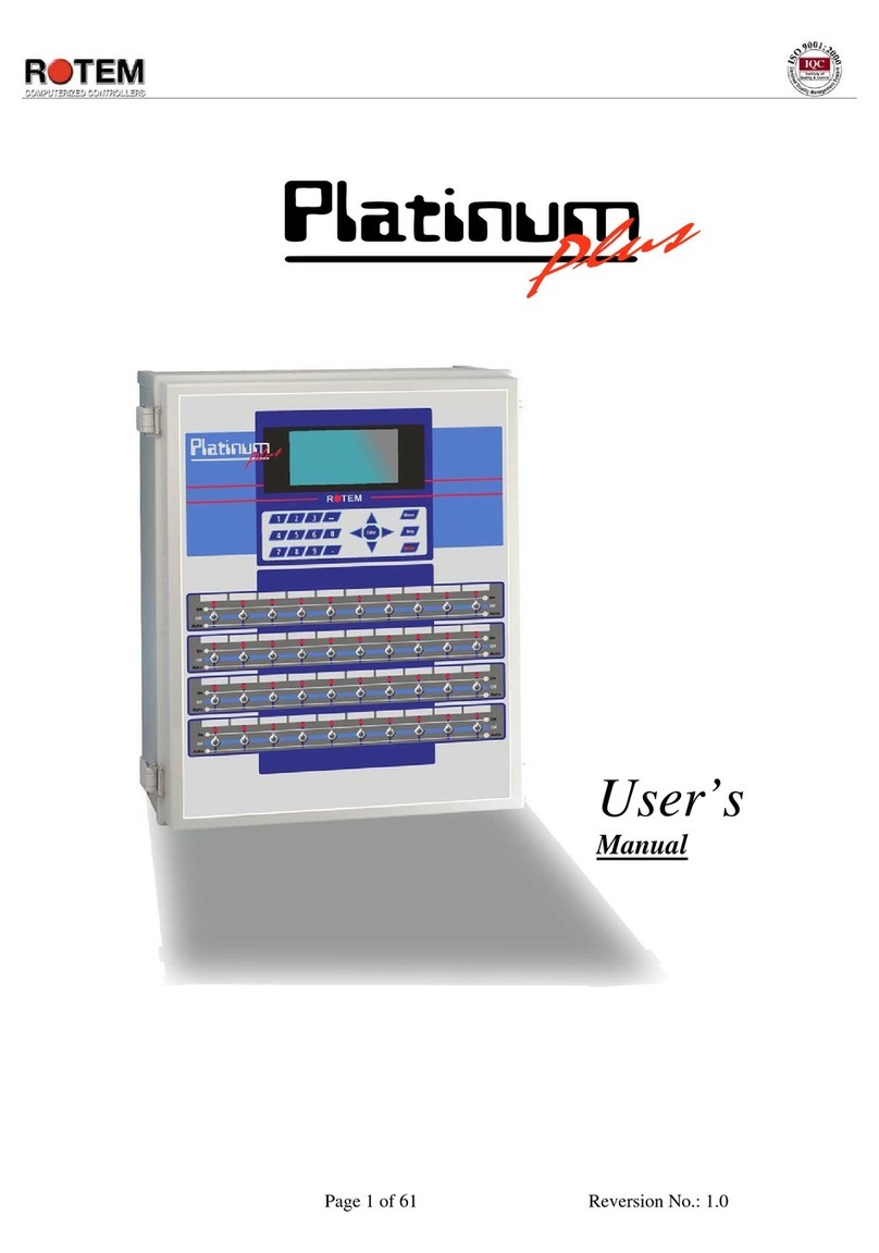
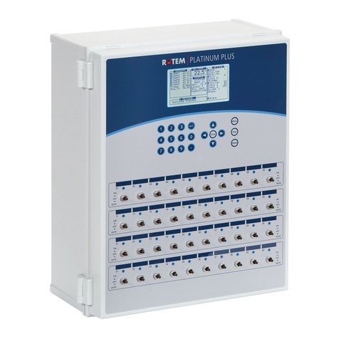
Rotem Platinum Pro User manual

Platinum Pro
Controllers
Installation Manual
P/N: 110472

Warranty & Limitation of Liability
1. Rotem warrants that the product shall be free of defects in materials or workmanship and will
conform to the technical specification for a period of 1 (one) year from the date of initial
installation on site (the "warranty period").
2. Rotem warrants that during said warranty period, any item/items or part/parts of equipment
found defective with respect to materials or workmanship or which do not conform to the technical
specification shall be repaired or replaced (at Rotem's sole discretion), free of charge.
3. During the warranty period, in the event of an alleged defect, authorized resellers in relevant
regions should be notified as soon as possible from the date of noticing the said defect, but no
longer than thirty (30) days from such a discovery. The report shall include (1) a short description
of the defects noticed (2) type of card / component and its matching serial number.
4. Rotem's sole liability under this warranty is the repair or replacement of the defective item of
product.
5. Load cells are not covered by Rotem’s warranty.
Conditions and Limitations
1. Rotem will not be responsible for any labor costs or expenses associated with replacement of
defective items or other parts of the product or repair.
2. This warranty shall not cover: (i) product or part therein which has been modified (without prior
written approval of Rotem), or (ii) product or part therein which has not handled or installed by an
authorized reseller of Rotem or (iii) product or part therein which has either handled or installed
not in strict accordance with Rotem's instructions, (iv) products which were used for function other
than agriculture industry.
3. This warranty will not apply in the following cases: (i) if all components of the product are not
originally supplied by Rotem (ii) the defect is the result of an act of nature, lighting strikes,
electrical power surge or interruption of electricity (iii) the defect is the result of accident, misuse,
abuse, alteration, neglect, improper or unauthorized maintenance or repair.
Rotem warns and alerts all users that the Product is inherently complex and may not be
completely free of errors. Rotem's products are designed and manufactured to provide reliable
operation. Strict tests and quality control procedures are applied to every product. However, the
possibility that something may fail beyond our control exists. Since these products are
designed to operate climate control and other systems in confined livestock environments,
where failure may cause severe damage, the user should provide adequate backup and alarm
systems. These are to operate critical systems even in case of a Rotem system failure.
Neglecting to provide such a backup will be regarded as the user’s willingness to accept the risk
of loss, injury and financial damage.
In no event will Rotem be liable to a user or any third party for any direct, indirect, special,
consequential or incidental damages, including but not limited to any damage or injury to
business earnings, lost profits or goodwill, personal injury, costs of delay, any failure of delivery,
costs of lost or damaged data or documentation, lost or damaged products or goods, lost sales,
lost orders, lost income.
Except for the above express warranty, Rotem makes no other warranties, express or implied,
relating to the products. Rotem disclaims and excludes the implied warranties of merchantability
and fitness for a particular purpose. No person is authorized to make any other warranty or
representation concerning the performance of the products other than as provided by Rotem.
Software Version: 6.0X
Document Version: 1.4
3 Platinum Controllers |6.0X
Table of Contents
1Front Matter .................................................................................................. 4
1.1 Introduction........................................................................................................................4
1.2 Conventions .......................................................................................................................4
1.3 Contact Information...........................................................................................................4
1.4 Document Information ......................................................................................................4
2Precautions................................................................................................... 5
2.1 Grounding ..........................................................................................................................5
2.2 Filtering...............................................................................................................................5
2.3 Checking the Battery Level ..............................................................................................5
2.4 Frequency Inverters ..........................................................................................................5
3Technical Details.......................................................................................... 6
3.1 Specifications ....................................................................................................................6
3.2 Layout .................................................................................................................................7
4Site Preparation............................................................................................ 8
4.1 Mounting............................................................................................................................. 8
4.2 Drilling ................................................................................................................................9
5High Voltage Wiring ................................................................................... 11
5.1 Power Supply ...................................................................................................................11
5.1.1 RPLP Wiring .................................................................................................................12
5.2 Relay Wiring .....................................................................................................................12
5.3 Winch Card Relay Wiring................................................................................................14
5.4 Completing the Wiring ....................................................................................................15
6Low Voltage Wiring .................................................................................... 16
6.1.1 Analog Card DIP Switches ...........................................................................................16
6.1.2 Analog Input Wiring Diagram for Temperature Sensors ..............................................17
6.1.3 Analog Input Wiring Diagram for CO2 and Light Sensor .............................................17
6.1.4 Analog Input Wiring Diagram for Potentiometers.........................................................18
6.1.5 Analog Input Wiring Diagram for Humidity Sensors.....................................................19
6.2 Weather Station Wiring ...................................................................................................19
6.3 Digital Input Wiring..........................................................................................................21
6.4 Analog Output Wiring......................................................................................................22
6.5 Alarm Card Wiring ...........................................................................................................23
6.6 Communication Card Wiring ..........................................................................................25

Platinum Controllers |6.0X 4
1 FRONT MATTER
This section includes information on the manual and general information.
1.1 Introduction
Rotem manuals provide easy-to-use information regarding the installation, operation, long/short term
planning and parts listing (this manual may not deal with all of the above subjects). The table of
contents is an outline of the relevant information in this manual.
Read this manual before operating your Rotem product. Using this equipment for any other purpose or
in a way not within the operating recommendations specified in this manual voids the warranty and may
cause personal injury. If you have any questions or comments regarding your product, please contact
your local Rotem dealer.
1.2 Conventions
NOTE: Notes provide important details regarding specific procedures.
CAUTION Cautions alert you to potential damage to the controller if the procedures are not
followed carefully.
WARNING! Warnings alert you to potentially hazardous situations which, if not avoided could
result in death or personal injury.
1.3 Contact Information
Rotem Control and Management Email: support@rotem.com Website: www.rotem.com
1.4 Document Information
Revision History
Revision Level / Date
Section Affected
Description
1.0/ February 2015
Release document
1.1 / May 2015
3.1
Edited spec
1.2 / August 2015 3.1 Certification
1.3 / January 2016
Updated multiple sections
1.4 / January 2017
3.1
Edited spec
© 2011 Rotem Corp. All rights reserved. Document Number: 110472 Revision Number: 1.4
No part of this publication may be reproduced, stored in an automated data file or made public in any
form or by any means, whether electronic, mechanical, by photocopying, recording or in any other
manner without prior written permission of the publisher. Rotem will not accept responsibility for
damage resulting from the use of this manual. Rotem also reserves the right to make changes and
improvements to its products and/or the associated documentation without prior notice.

5 Platinum Controllers |6.0X
2 PRECAUTIONS
●Grounding
●Filtering
●Checking the Battery Level
2.1 Grounding
●Always connect temperature and sensor shields to earth ground. Avoid mixing high voltage
wiring with sensor and low voltage wiring.
●Keep the controller as far as possible from heavy contactor boxes and other sources of
electrical interference.
●Do not connect communication wire shields, which go from one house to another at both
ends. Connect them at one end only. Connection at both ends can cause ground loop
currents to flow, which reduce reliability.
●The COM connection for communications is not the shield wire. The COM, RX and TX wires
must connect to each other at all controllers.
2.2 Filtering
If this installation includes a power inverter to drive variable speed fans, install an EMI filter in front of
the inverter, according to the specifications provided by the inverter manufacturer. Refer to the inverter
documentation.
2.3 Checking the Battery Level
Check the battery once a year. The output must be 2.8 volts (minimum). Authorized personnel only
must replace the battery if the output is below the minimum required level or every five years.
2.4 Frequency Inverters
Frequency inverters can cause severe electrical and electromagnetic interference. Therefore, when
employing a frequency inverter, it is critical that you carefully follow the manufacturer's installation
instructions. In particular verify:
●that the cable shielding between the inverter and any motor meets industry standards
●proper grounding of the inverter's chassis and motor power cable
●proper grounding of low voltage cable shield wire
●that the controller and inverter cables are kept in separate conduits or wire bundles
1. Controller
2. Inverter
3. Place the controller at least five meters from the inverter

Platinum Controllers |6.0X 6
3 TECHNICAL DETAILS
●Specifications
●Layout
3.1 Specifications
Input Power Voltage
100 – 240 VAC
2.2 Amp, 50-60Hz
Relay Loads
30.0 Amps Active Load; 2 HP Inductive Load, 250 Volts, non-Fused for C-P3-NO-RC-30A relay cards
20.0 Amps Active Load; 1 HP Inductive Load, 250 Volts, non-Fused for C-P3-NC-RC-30A relay cards
20.0 Amps Active Load; 1 HP Inductive Load, 250 Volts, non-Fused for C-P3-WC-RC-30A relay cards
Analog Inputs
0 - 5 Volts, 20 milliamps maximum
Analog Output
0 - 10 Volts
Maximum load: 20 mA
Digital Inputs
5 Volts, 1.5 mA, dry contact
Operating Temperature Range
0° to +50° C (32° to 125° F)
Enclosure
Water and dust tight
Fuses
3 Amps, 250 volts
Certification

7 Platinum Controllers |6.0X
3.2 Layout
The following illustration displays the main elements in Platinum Pro units.
Figure 1: Platinum Pro Layout
NOTE: Figure 1 is an example layout. Each installation can differ.
Platinum PRO supports:
●Analog input, digital input, analog output cards
●1 x Platinum Extension unit
●4 x Rotem Light Dimmers (RLD)
●4 X Rotem Digital Thermostats (RDT-5)2 x Rotem Scale Units
●1 x HUB-4
NOTE: This manual provides wiring instructions for the cards. Refer to the products respective
manuals for installation instructions.

Platinum Controllers |6.0X 8
4 SITE PREPARATION
The following sections detail the initial steps required when placing the Platinum controllers.
4.1 Mounting
1. Remove the mounting plates (x4) and screws
(x8) from the plastic bag.
2. Fasten the mounting plates to the corners of
the controller using four screws.
3. Place the controller box on the wall and make sure it is leveled (use a spirit level).
4. Using the remaining screws, secure the controller to the wall.

9 Platinum Controllers |6.0X
4.2 Drilling
Drill holes on the side and bottom of controller box according to the steps defined below. Use these
holes to route the low and high voltage cables.
CAUTION Make sure not to damage cards when drilling holes. Locate holes properly before
drilling!
1. Drill a hole on the right side of the controller box. Verify that the low voltage cables go through
the hole properly.
Figure 2: Drilling on the Side
2. Drill a hole on the bottom side of the controller box. Verify that the high voltage cables being
used fit through the hole properly.
NOTE: Rotem recommends drilling at least two (2) holes, placed as close to the front edge as
possible (to avoid crowding the wiring).

Platinum Controllers |6.0X 10
Figure 3: Drilling on the Bottom
3. Clean the holes from plastic shards. Verify that rims of holes are smooth.
Figure 4: Hole locations

11 Platinum Controllers |6.0X
5 HIGH VOLTAGE WIRING
This section details how to wire the controller’s high voltage wiring:
WARNING! Before beginning, disconnect the power supply!
CAUTION Only a qualified electrician may perform the electrical installation!
●Power Supply, page 11
●Relay Wiring, page 12
●Winch Card Relay Wiring , page 14
CAUTION Avoid mixing high voltage wiring with sensor and low voltage wiring.Keep the
controller as far as possible from heavy contactor boxes and other sources of
electrical interference.
5.1 Power Supply
●Main grounding wire should come connected to the ground terminal (1).
oConnect electricity to the controller power supply (2).
oConnect the grounding strip to the grounding rod (3).
●230 VAC, 50/60 Hz; USA: L1, L2; ROW line, neutral (4)
Figure 5: Power Supply Wiring Diagram

Platinum Controllers |6.0X 12
5.1.1 RPLP Wiring
The following section details how to wire an RPLP Lighting Protector unit to the power supply.
CAUTION Install the RPLP, 230 V only (part number P-RPLP-1-V2)!
On the RPLP's protected side:
1. Connect the RPLP grounding wire to the Platinum grounding terminal.
2. Connect the RPLP Neutral terminal to the Platinum L1 terminal.
3. Connect the RPLP Line terminal to the Platinum L2 terminal (4).
o230 VAC, 50/60 Hz;
oUSA: Ground, L1, L2;
oROW: Ground, line, neutral
Figure 6: Wiring the RPLP
5.2 Relay Wiring
This procedure details how to connect output relays to poultry house devices.
1. Connect the control phase commons to the relays’ contacts (the common wire to all relays
with the same function).
Figure 7: Control Phase Commons

13 Platinum Controllers |6.0X
Figure 7 key
1 Phase common
2. Connect the relay cables to each inlet/curtain/device.
Figure 8: Relay Cable Connections
Figure 8 key
1 Cable to device 2 Phase common
3. On the sticker below each relay, write the name of the device connected to the relay.
4. Locate the bag of stickers placed on the inside of the Platinum door.
Figure 9: Controller labels
5. On the front of the controller, place the appropriate label above the switch that corresponds
with the electrical setup.

Platinum Controllers |6.0X 14
5.3 Winch Card Relay Wiring
This procedure details how to connect Winch Cards to the inlets. Winch cards simplify backup (opening
air sources such as inlets) in a power/heating event.
NOTE: Winch Cards are optional. Users employing an RBU-27 do not require Winch Cards. Rotem
recommends that users employing an RBU-5 or RBU-3 install Winch Cards.
NOTE: Use relays 7 – 10 for winch card relays. Winch cards are equipped with two Normally Close
relays.
1. Connect separate control phase commons for each inlet or curtain.
Figure 10: Winch Card Control Phase Commons
1: Open curtain (Normally Open Relay)
2: Close curtain (Normally Open Relay)
2. Connect the output wires to the required device.
Figure 11: Connecting the Output Wire to Inlets/Curtains
1: Open curtain (Normally Closed (NC) relay is wired to the opening gear)
2: Close curtain (Normally Open (NO) relay is wired to the opening gear)
3: Connect control phase wire to:
oL1 or L2 power port OR
oRBU-27 Backup device

Platinum Controllers |6.0X 16
6 LOW VOLTAGE WIRING
The following section details the:
●Analog Card DIP Switches
●Analog Input Wiring Diagram for Temperature Sensors
●Analog Input Wiring Diagram for CO2 and Light Sensor
●Analog Input Wiring Diagram for Potentiometers
●Analog Input Wiring Diagram for Humidity Sensors
Platinum' analog input card (P/N: C-P3-RAIC12) supports up to 12 analog devices: temperature, light,
CO2, and humidity sensors, wind direction detectors, and potentiometers. The analog input cards
include of surge and lightening protection circuits and do not require additional external protections.
●Use 22 AWG or lower, shielded cable only!
●Connect every analog input device's shield to the controller's safety ground!
●Every COM input is correct and more than one sensor can be connected to a COM input.
6.1.1 Analog Card DIP Switches
The RAIC-12 has the following ports:
●T1 – T8: Eight dedicated
temperature sensor
inputs
●IN1 – IN4: Four input
ports defined using dip
switches
●Four COM ports
●+12V: Two dedicated
humidity sensor voltage
(12V) ports
●3.3V: Two dedicated
potentiometer voltage
(3.3V) ports
To configure the IN1 – IN4 ports move one dip switch to ON in each set of ports. L
CAUTION Leaving all switches in the Off position or placing more than one switch in the On
position in a set nullifies those functions!
•DIP Switch 1: 4 – 20 mA (CO2 and light
sensors)
•DIP Switch 2: 0 – 5V (humidity)
•DIP Switch 3: Potentiometer and wind
direction sensors
•DIP Switch 4: Temperature sensor

17 Platinum Controllers |6.0X
6.1.2 Analog Input Wiring Diagram for Temperature Sensors
●Connect the temperature sensor to an input and COM port. Terminals 1 - 8: These inputs
support temperature sensors only.
●IN1 – IN4: These are optional temperature sensor inputs (turn DIP Switch 4 (T) on each set
as required).
Figure 26 shows an example of temperature sensor wiring.
Figure 13: Temperature Sensor Wiring
Figure 13 key
1 T1 input 4 IN4 input
2 T3 input 5 Shield wire connected to grounding strip
3 IN2 input
6.1.3 Analog Input Wiring Diagram for CO2 and Light Sensor
1. Connect each sensor to an input and COM port.
2. IN1 – IN4: Turn on DIP Switch 1 on each set as required.
Figure 14 shows an example of CO2 and light sensor wiring

Platinum Controllers |6.0X 18
Figure 14: Light and CO2 Sensors Wiring
Figure 14 key
1 IN2 3 IN4
2 IN1 4 Shield wire connected to grounding strip
6.1.4 Analog Input Wiring Diagram for Potentiometers
1. Connect each potentiometer (10 - 20 KOhm) to an input, a COM, and 3.3V port.
2. IN1 – IN4: Turn on DIP Switch 3 on each set as required.
Figure 15 shows an example potentiometer wiring.
Figure 15: Potentiometer Wiring
Figure 15 key
1 3.3V

19 Platinum Controllers |6.0X
Figure 15 key
2 IN2
3 Shield wire connected to grounding strip
6.1.5 Analog Input Wiring Diagram for Humidity Sensors
1. Connect each humidity sensor to input, a COM, and +12V port.
2. IN1 – IN4: Turn on DIP Switch 2 on each set as required.
Figure 16 shows an example humidity sensor wiring setup.
Figure 16: Humidity Sensor Wiring
Figure 16 key
1 IN2 3 12V
2 IN1 4 Shield wire connected to grounding strip
6.2 Weather Station Wiring
Setting up a weather station (rain and wind direction sensor) requires the following wiring:
1. Wind direction sensor (P-WS-WDS) to RAIC-12:
a. Connect each wind direction sensor to an input, a COM, and POT port.
b. IN1 – IN4: Turn on DIP Switch 3 on each set as required.
2. Wind direction sensor to RDIC-12:
oConnect each wind direction sensor to an input and a COM port.
3. Rain Sensor (P-WS-WRS) to RDIC-12:
oConnect each sensor to an input and a COM port.

Platinum Controllers |6.0X 20
Figure 17: Weather Station Wiring
Figure 18: Weather Station Analog Input Card
Figure 19: Weather Station Digital Input Card
Table of contents
Other Rotem Controllers manuals

Rotem
Rotem platinum junior xl User manual

Rotem
Rotem Platinum PLUS User manual

Rotem
Rotem AC-2000 SE User manual

Rotem
Rotem Platinum Junior User manual

Rotem
Rotem Platinum PLUS User manual

Rotem
Rotem RLD 7.2 User manual

Rotem
Rotem SuperGuard User manual

Rotem
Rotem SuperGuard Guide

Rotem
Rotem Platinum PLUS User manual
Popular Controllers manuals by other brands

Parker
Parker Lucifer P4CN40 C Series Bulletin

Bard
Bard MC4000 SERIES Installation & parts manual

Advanced Control Technologies
Advanced Control Technologies th104 installation instructions

Murphy
Murphy iGUARD AL-02058B Specifications

Gewiss
Gewiss Chorus GWA1521 Technical manual

OptiSense
OptiSense PaintChecker industrial Operation manual