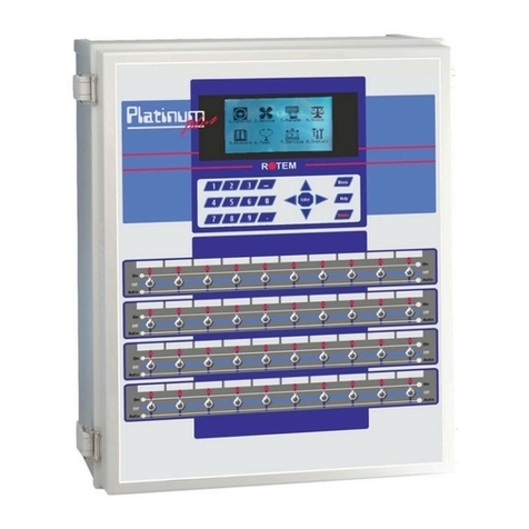
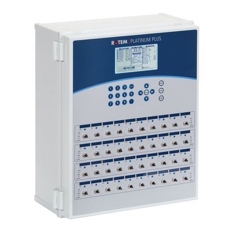
Rotem AC-2000 SE User manual

AC-2000 SE and PLUS
Pig Controllers
Installation Manual
P/N: 110118

Warranty & Limitation Of Liability
1. ROTEM warrants that the product shall be free of defects in materials or workmanship and
will conform to the technical specification for a period of 1 (one) year from the date of initial
installation on site (the "warranty period").
2. Load cells are not covered by ROTEM’s warranty.
3. ROTEM warrants that during said warranty period, any item/items or part/parts of equipment
found defective with respect to materials or workmanship or which do not conform to the
technical specification shall be repaired or replaced (at ROTEM's sole discretion), free of
charge.
4. During the warranty period, in the event of an alleged defect, authorized resellers in relevant
regions should be notified as soon as possible from the date of noticing the said defect, but no
longer than thirty (30) days from such a discovery. The report shall include (1) a short
description of the defects noticed (2) type of card / component and its matching serial number.
5. ROTEM's sole liability under this warranty is the repair or replacement of the defective item of
product.
Conditions and Limitations
1. ROTEM will not be responsible for any labor costs or expenses associated with replacement
of defective items or other parts of the product or repair.
2. This warranty shall not cover: (i) product or part therein which has been modified (without
prior written approval of ROTEM), or (ii) product or part therein which has not handled or
installed by an authorized reseller of ROTEM or (iii) product or part therein which has either
handled or installed not in strict accordance with ROTEM's instructions, (iv) products which
were used for function other than agriculture industry.
3. This warranty will not apply in the following cases: (i) if all components of the product are not
originally supplied by ROTEM (ii) the defect is the result of an act of nature, lighting strikes,
electrical power surge or interruption of electricity (iii) the defect is the result of accident,
misuse, abuse, alteration, neglect, improper or unauthorized maintenance or repair.
ROTEM warns and alerts all users that the Product is inherently complex and may not be
completely free of errors. ROTEM's products are designed and manufactured to provide reliable
operation. Strict tests and quality control procedures are applied to every product. However, the
possibility that something may fail beyond our control exists. Since these products are
designed to operate climate control and other systems in confined livestock environments,
where failure may cause severe damage, the user should provide adequate backup and alarm
systems. These are to operate critical systems even in case of a ROTEM system failure.
Neglecting to provide such a backup will be regarded as the user’s willingness to accept the risk
of loss, injury and financial damage.
In no event will ROTEM be liable to a user or any third party for any direct, indirect, special,
consequential or incidental damages, including but not limited to any damage or injury to
business earnings, lost profits or goodwill, personal injury, costs of delay, any failure of delivery,
costs of lost or damaged data or documentation, lost or damaged products or goods, lost sales,
lost orders, lost income.
Except for the above express warranty, ROTEM makes no other warranties, express or implied,
relating to the products. ROTEM disclaims and excludes the implied warranties of
merchantability and fitness for a particular purpose. No person is authorized to make any other
warranty or representation concerning the performance of the products other than as provided
by ROTEM.
Software Version:8.11
Document Version:1.9
Table of Contents
1Front Matter...................................................................................................4
1.1 Introduction........................................................................................................................4
1.2 Conventions.......................................................................................................................4
1.3 Contact Information...........................................................................................................4
1.4 Document Information ......................................................................................................4
2Precautions...................................................................................................5
2.1 Grounding...........................................................................................................................5
2.2 Filtering...............................................................................................................................5
2.3 Checking the Battery Level...............................................................................................5
2.4 Frequency Inverters ..........................................................................................................5
3Technical Specifications..............................................................................6
4Installation.....................................................................................................7
4.1 Mounting the Unit..............................................................................................................7
4.2 AC-2000 Plus Wiring..........................................................................................................7
4.2.1 AC-2000 Plus Board Layout...........................................................................................8
4.2.2 AC-2000 Plus Relays......................................................................................................8
4.2.3 AC-2000 Plus High Voltage Wiring (Relays)..................................................................9
4.2.4 AC-2000 Plus Terminals...............................................................................................10
4.2.5 AC-2000 Plus Low Voltage Wiring (Terminals)............................................................11
4.2.6 AC-2000 Plus Communication .....................................................................................11
4.3 AC-2000 SE Wiring ..........................................................................................................12
4.3.1 AC-2000 Board Layout.................................................................................................12
4.3.2 AC-2000 SE Relays......................................................................................................13
4.3.3 AC-2000 SE High Voltage Wiring (Relays) ..................................................................14
4.3.4 AC-2000 SE Terminals.................................................................................................15
4.3.5 AC-2000 SE Low Voltage Wiring (Terminals) ..............................................................16
4.3.6 MUX / RCLP Wiring......................................................................................................17
5Configuration..............................................................................................18
5.1 Configuration (Menu 91) .................................................................................................18
5.2 Ventilation Table (Menu 92)............................................................................................19
5.3 Relay Layout (Menu 93)...................................................................................................20
5.3.1 Manual Relay Operation...............................................................................................22
5.3.2 Relay Record................................................................................................................22
5.4 Sensor Layout (Menu 94)................................................................................................22
5.5 Setup Curtains (Menu 95) ...............................................................................................23
6Troubleshooting Guide..............................................................................24
7Electrical Grounding ..................................................................................26
7.1 Ground Rods....................................................................................................................26
7.2 Ground Wire.....................................................................................................................26
7.3 Ground Clamps................................................................................................................26
7.4 What Should Be Grounded?...........................................................................................27
7.5 Lightening Protection......................................................................................................27
7.5.1 Power Line Protection...................................................................................................27
7.5.2 Communication Line Protection....................................................................................27
8Appendix: Installing a CO2 Sensor...........................................................28
8.1 Low Voltage Wiring .........................................................................................................28
8.2 Configuring the CO2 Sensor ..........................................................................................29

AC-2000 |8.10/8.11 4
1 FRONT MATTER
This section includes information on the manual and general information.
1.1 Introduction
Rotem manuals provide easy-to-use information regarding the installation, operation, long/short term
planning and parts listing (this manual may not deal with all of the above subjects). The table of contents is
an outline of the relevant information in this manual.
Read this manual before operating your Rotem product. Using this equipment for any other purpose or in a
way not within the operating recommendations specified in this manual will void the warranty and may
cause personal injury.
If you have any questions or comments regarding your product, please contact your local Rotem dealer.
1.2 Conventions
NOTE: Notes provide important details regarding specific procedures.
CAUTION Cautions alert you to potential damage to the controller if the procedures are not
followed carefully.
WARNING! Warnings alert you to potentially hazardous situations which, if not avoided could
result in death or personal injury.
1.3 Contact Information
Rotem Control and Management
Email: support@rotem.com
URL: www.rotem.com
1.4 Document Information
Revision History
Revision Level / Date
Sect. Affected
Description
1.0 / Sept 2011 Release document
1.1 / Feb 2012
4.2.6
Added section
1.2 / Sept 2012
8.07
1.3 / Oct 2012
5.3/Manual
Changes in variables/Formatting changes
1.4 / Feb 2013 4.2.3/4.3.3 Changes in wiring diagram
1.5 / March 2014
8.10
1.6 / July 2014
2.4
Frequency inverters
1.7 / Feb 2015 8.11
1.8 / Sept 2016
4.2
Update pictures
1.9 / Dec 2016
3
Updated specs
© 2011 Rotem Corp.
All rights reserved.
Document Number:110118 Revision Number:1.9
No part of this publication may be reproduced, stored in an automated data file or made public in any form
or by any means, whether electronic, mechanical, by photocopying, recording or in any other manner
without prior written permission of the publisher.
Rotem will not accept responsibility for damage resulting from the use of this manual. Rotem also reserves
the right to make changes and improvements to its products and/or the associated documentation without
prior notice.

5 AC-2000 |8.10/8.11
2 PRECAUTIONS
•Grounding
•Filtering
•Checking the Battery Level
•Frequency Inverters
2.1 Grounding
•Always connect temperature and sensor shields to earth ground. Avoid mixing high voltage
wiring with sensor and low voltage wiring.
•Keep the controller as far as possible from heavy contactor boxes and other sources of electrical
interference.
•Do not connect communication wire shields, which go from one house to another at both ends.
Connect them at one end only. Connection at both ends can cause ground loop currents to flow,
which reduce reliability.
•The COM connection for communications is not the shield wire. The COM, RX and TX wires
must connect to each other at all controllers.
2.2 Filtering
If this installation includes a power inverter to drive variable speed fans, install an EMI filter in front of the
inverter, according to the specifications provided by the inverter manufacturer. Refer to the inverter
documentation.
2.3 Checking the Battery Level
Check the battery once a year. The output must be 2.7 volts (minimum). Authorized personnel only must
replace the battery if the output is below the minimum required level or every five years.
2.4 Frequency Inverters
Frequency inverters can cause severe electrical and electromagnetic interference. Therefore, when
employing a frequency inverter, it is critical that you carefully follow the manufacturer's installation
instructions. In particular verify:
•that the cable shielding between the inverter and any motor meets industry standards
•proper grounding of the inverter's chassis and motor power cable
•proper grounding of low voltage cable shield wire
•that the controller and inverter cables are kept in separate conduits or wire bundles
1. Controller
2. Inverter
3. Place the controller at least five meters from the inverter

AC-2000 |8.10/8.11 6
3 TECHNICAL SPECIFICATIONS
Input Power Voltage
One Phase 115 ± 10 VAC (USA and Canada)
230 ± 20 VAC (Outside USA and Canada)
0.5Amp, 50-60Hz
Relay Loads
5.0 Amps, 250 Volts, Fused
Analog Inputs
0 - 11 Volts, 10 Milliamps Maximum
Analog Output
0 - 10 Volts:
Current Limited with 100-Ohm Resistor
Digital Inputs
5 ma @ 5 Volts, Dry Contact
Operating Temperature Range
0° to +50° C (32° to 125° F)
Enclosure
Water and Dust Tight
Fuses
Main fuse: 0.315 Amps, 250 Volts
Others: 5 Amps, 250 Volts

7 AC-2000 |8.10/8.11
4 INSTALLATION
This manual details the installation procedures for the AC-2000 SE and AC-2000 Plus Pig Controllers.
•Mounting the Unit, page 7
•AC-2000 Plus Wiring, page 7
•AC-2000 SE Wiring, page 12
4.1 Mounting the Unit
1. Install the AC-2000 in a dry well lighted area, preferably in an annex to the main poultry house.
2. Mount it using the three holes provided; one in each of the left and right lower corners, accessible
from the front under the terminal strip cover, and one top center in the back. The top center hole is a
keyhole variety.
3. Install the screw for this hole first to about 0.1 inches of the wall surface.
4. Hang the controller on this screw. Install the other two screws to fasten the AC-2000.
CAUTION Always connect temperature and sensor shields to earth ground. However, do not
connect communication wire shields, which go from one house to another at both ends.
Connect them at one end only. Connection at both ends can cause ground loop currents
to flow, which reduce reliability.
CAUTION The COM connection for communications is not the shield wire. The COM, RX and TX
wires must connect to each other at all AC-2000 controls.
CAUTION Avoid mixing high voltage wiring with sensor and low voltage wiring.
CAUTION Keep the AC-2000 as far as possible from heavy contactor boxes and other sources of
electrical interference.
Refer to Electrical Grounding, page 26 for information on grounding the unit.
4.2 AC-2000 Plus Wiring
The following sections detail the AC-2000 Plus wiring.
•AC-2000 Plus Relays, page 8
•AC-2000 Plus High Voltage Wiring (Relays), page 9
•AC-2000 Plus Terminals, page 10
•AC-2000 Plus Low Voltage Wiring (Terminals), page 11
•AC-2000 Plus Communication Wiring, page 11

AC-2000 |8.10/8.11 8
4.2.1 AC-2000 Plus Board Layout
4.2.2 AC-2000 Plus Relays
1. Relays 1 to 19: Each pair of terminals goes to one relay. These relays are fused with a
5-ampere, 250-volt slow blow fuses. The relays are normally open when not powered.
2. Relay 20: Three terminal blocks: This relay normally serves as an alarm relay. It is also
fused with a 5 ampere, 250 volt slow blow fuse, and can serve as an ordinary relay:
oNC: Normally closed contact
oCom: Common contact
oNO: Normally open contact
3. Power: Three terminal blocks:
oNeutral (N): Connect to the Neutral Power line.
oPhase (~): Connect to the Phase Power line.
oGround (GND): Connect to a solid earth safety ground, normally with the bare safety
ground wire, or a green wire.
4. Ground: Connect the ground wire to the electrical system.

9 AC-2000 |8.10/8.11
4.2.3 AC-2000 Plus High Voltage Wiring (Relays)
NOTE: The device connections (fan, heat, cool, etc.) that are shown in the drawing, are examples
only!
CAUTION Connect the AC-2000 Plus power input to the protected output only!

AC-2000 |8.10/8.11 10
4.2.4 AC-2000 Plus Terminals
1. Communications: Three terminal blocks for PC communication using the optional
multiplexor, MUX-2.
oRX (20): Receive into AC-2000 PLUS. With multiple controls, connect all the RX pins
together. Connect to TX at Multiplexor only.
oTX (19): Transmit from AC-2000 PLUS With multiple controls, connect all the TX pins
together. Connect to RX only at Multiplexor only.
oCOM (18):Ground reference for communications. Do not connect shields to this pin.
Connect to COM at multiplexor also.
2. Relay Extension:Com (1) - The relay extension box such as the REB-8 may be located up
to 10 feet from the AC-2000 PLUS. Do not connect the shield to this terminal. Connect the
shield to earth ground only at one end of the cable to avoid ground loops.
oData (2): This line carries data to the relay extension.
oClk (3): This line carries a clocking signal for use by the relay extension.
3. Not used.
4. 6 Temperature Sensors (8, 9, 10, 25, 26, 27): The temperature sensor is a 2 wired black
shielded cable thermistor (RTS-2). Connect one wire to the temperature sensor terminal and
the other to common (11, 28)*Polarity does not matter.
5. Analog Inputs:
oHumidity Sensor (30, 31, 32): Connect according to wire colors (White, Red, Black).
oAn.2 (13): Humidity Outside Humidity input. Connect the white wire of the Humidity sensor
to An.2 and the red and black together with the Humidity input red and black.
oAn.3 (14): Pressure sensor (Connect + red wire to An.3 and Black – wire to Common).
6. Analog Outputs:
oAn.1 (33): 0 to 10V- Light Intensity control signal
oAn.2 (34): 0 to 10V- Variable speed control signal
oCOM (29):Connect the common wire of An.1 & 2 to terminal 29
7. Digital Inputs:
oDig 1 (15): Feed overtime alarm input or wind direction selection
oDig 2 (16):Feed counter
oDig 3 (17): Water meter

11 AC-2000 |8.10/8.11
4.2.5 AC-2000 Plus Low Voltage Wiring (Terminals)
NOTE: Connect each cable’s shielding wire to the grounding strip. The drawing above is an example
only.
NOTE: Users employing a CO2 sensor, refer to Appendix: Installing a CO2 sensor.
4.2.6 AC-2000 Plus Communication
AC-2000 Plus is wired to a MUX/Communicator via:
•an internal communication card (P/N C-AC-2000-C232). Connect the communication wires
shown in Section 4.2.5 directly to the MUX / Communicator OR
•an external RCLP card (see MUX / RCLP Wiring page 17, for wiring instructions)

AC-2000 |8.10/8.11 12
4.3 AC-2000 SE Wiring
The following sections detail the AC-2000 SE wiring.
•AC-2000 Board Layout, page 12
•AC-2000 SE Relays, page 13
•AC-2000 SE High Voltage Wiring (Relays), page 14
•AC-2000 SE Terminals, page 15
•AC-2000 SE Low Voltage Wiring (Terminals), page 16
•MUX / RCLP Wiring, page 17
4.3.1 AC-2000 Board Layout
1 Ground strip 5 Key board connector
2 5 Amp fuse 6 LCD connector
3 Transformer 7 Static pressure sensor (option)
4 Voltage regulator 8 Battery

13 AC-2000 |8.10/8.11
4.3.2 AC-2000 SE Relays
1. Relays 1 to 11: Each pair of terminals goes to one relay. These relays are fused with a
5-ampere, 250-volt slow blow fuses. The relays are normally open when not powered.
2. Relay 12: Three terminal blocks: This relay normally serves as an alarm relay. It is also fused
with a 5 ampere, 250 volt slow blow fuse, and can serve as an ordinary relay:
oNC: Normally closed contact.
oCom: Common contact.
oNO: Normally open contact.
3. Power: Three terminal blocks:
oNeutral (N): Connect to the Neutral Power line.
oPhase (~): Connect to the Phase Power line.
oGround (GND): Connect to a solid earth safety ground, normally with the bare safety
ground wire, or a green wire.
4. Ground: Connect the ground wire to the electrical system.

AC-2000 |8.10/8.11 14
4.3.3 AC-2000 SE High Voltage Wiring (Relays)
NOTE: The device connections (fan, heat, cool, etc.) that are shown in the drawing are examples
only!
CAUTION Connect the AC-2000 SE power input to the protected output only!

15 AC-2000 |8.10/8.11
4.3.4 AC-2000 SE Terminals
1. Not used.
2. Communications: Three terminal blocks for PC communication using the optional multiplexor,
MUX-2.
oRX:Receive into AC-2000 SE. With multiple controls, connect all the RX pins together.
Connect to TX at Multiplexor only.
oTX:Transmit from AC-2000 SE With multiple controls, connect all the TX pins together.
Connect to RX only at Multiplexor only.
oCOM:Ground reference for communications. Do not connect shields to this pin. Connect
to COM at multiplexor also.
3. Temperature Sensors: The temperature sensor is a 2 wired black shielded cable thermistor
(RTS-2). Connect one wire to the temperature sensor terminal and the other to common
(Polarity does not matter).
4. Analog Inputs:
oAn.1:Humidity sensor with wire connections according to wire colors.
oAn.2: Humidity Outside Humidity input. Connect the White wire of the Humidity sensor to
An.2 and the Red and Black together with the Humidity input Red and Black.
oAn.3: Pressure sensor (Connect Red (+) wireAn.3; Black (–) Common).
5. Analog Outputs:
oAn.1:0 to 10V- Light Intensity control signal.
oAn.2:0 to 10V- Variable speed control signal.
6. Digital Inputs:
oDig 1:Feed overtime alarm input or wind direction selection.
oDig 2:Feed counter.
oDig 3: Water meter.
7. Relay Extension:Com - The relay extension box such as the REB-8 may be located up to 10
feet from the AC-2000 SE. Do not connect the shield to this terminal. Connect the shield to
earth ground only at one end of the cable to avoid ground loops.
oData: This line carries data to the relay extension.
oClk: This line carries a clocking signal for use by the relay extension.

AC-2000 |8.10/8.11 16
4.3.5 AC-2000 SE Low Voltage Wiring (Terminals)
•Connect the sensor shielding wire to the grounding strip.
o16 –Analog Input 2
o17 –Analog Input 3
o18 –Analog Input 1
NOTE: The above illustration is an example only!

17 AC-2000 |8.10/8.11
4.3.6 MUX / RCLP Wiring

AC-2000 |8.10/8.11 18
5 CONFIGURATION
Table 1: Configuration (Version 8.07)
91 Configuration
92 Ventilation Levels
93 Relay Layout
94 Sensor Layout
95 Setup Curtains
96 System Variables
97 Password
Table 2: Configuration (Version 8.09)
91 Configuration
92 Ventilation Levels
93 Relay Layout
94 Sensor Layout
95 Setup Curtains
96 System Variables
97 Password
98 Wind Chill
The installation menus are not shown on the front panel of the control. They are not used in the day-to-day
operation of the control, but only during initial installation.
To get to these menus from the default display:
1. Press MENU.
2. Enter the menu number from the Installation Menu.
•Configuration (Menu 91), page 18
•Ventilation Table (Menu 92), page 19
•Relay Layout (Menu 93), page 20
•Sensor Layout (Menu 94), page 22
•Setup Curtains (Menu 95), page 23
5.1 Configuration (Menu 91)
•Empty House: This mode prevents new alarms from starting. Alarms that were active before
entering empty house continue to be active. While in Empty House mode a blinking indication
message constantly appears. Use this mode between herds when the house is empty and you
don’t want the alarms to operate. Default: 'off'.
Automatically exiting from an empty house occurs in the following cases:
oChanging growth day
oNew herd
oSwitching from day '0' to day '1'
•Celsius or Fahrenheit selection.
•Communication baud rate (1200, 2400, 4800 or 9600) for hookup to a personal computer or
modem.

19 AC-2000 |8.10/8.11
•Maximum number of ventilation levels: The AC-2000 supports up to 20 ventilation levels.
However, limiting this to a smaller number simplifies the ventilation table.
•Analog out 1 (0-3):
•Analog out 1/Analog out 2 (0-3) (0-4 AC-2000 Plus, Version 8.11):
o'0': None
o'1': Variable fan
o'2': Light
o'3': Variable heater
o'4': Variable fan #2 (AC-2000 Plus, Version 8.11)
•First tunnel level: When using tunnel ventilation, enter the ventilation level (in accordance with
the ventilation and curtain level tables) at which the system starts tunnel ventilation.
•Number of heating zones:The AC-2000 can control up to six separate heating zones. For one
zone only, the average temperature controls the heaters. For two or more zones, the assigned
sensors control the heaters in each zone (Menu 94).
•Automatic continuous temperature adjustment: The AC-2000 uses precisely the values
entered in the temperature tables for each growth period if this is ‘0’. For automatic interpolation
between these entries, enter ‘1’. The options are as follows:
o'0': without
o'1': temperature
o'2': temperature and Min/Max
•Barn Number:This identifies the particular barn for the personal computer at home. Use a
unique number for each AC-2000 to enable the communication program to identify each
controller.
•Curtain opening and closing times:Enter the number of seconds it takes the curtains to go
from fully closed to fully open, and from fully open to fully closed for each curtain. The AC-2000
uses this value to calculate the run time for each curtain when it moves them.
•Tunnel curtain opening and closing times
•Measurement Unit: Set the unit to be used when setting the house/shed dimensions. This
variable is used in calculating the wind chill correction factors (see the User Manual).
•Air Capacity Unit: ‘0’ for M3/hour, ‘1’ for CFM (cubic feet per minute); Default value = ‘0’
5.2 Ventilation Table (Menu 92)
Ventilation Level Ventilation Groups On Minutes Off Minutes Diff Var Var #2
1 1 0 0 0 0 0 0 0 0 0 0 0 0.5 9.5 0 0 0
2 1 0 0 0 0 0 0 0 0 0 0 0 1.0 9.0 0 0 0
3 1 0 0 0 0 0 0 0 0 0 0 0 2.0 8.0 0 0 0
4 1 0 0 0 0 0 0 0 0 0 0 0 3.0 7.0 0 0 0
5 1 0 0 0 0 0 0 0 0 0 0 0 5.0 5.0 0 0 0
6 1 0 0 0 0 0 0 0 0 0 0 0 1.0 0.0 0 0 0
7 1 2 0 0 0 0 0 0 0 0 0 0 0.5 1.0 0 0 0
8 1 2 0 0 0 0 0 0 0 0 0 0 1.0 1.0 0 0 0
9 1 2 0 0 0 0 0 0 0 0 0 0 1.0 0.0 0 0 0
10 1 2 3 0 0 0 0 0 0 0 0 0 0.5 1.0 0 0 0
11 1 2 3 0 0 0 0 0 0 0 0 0 1.0 1.0 0 0 0
12 1 2 3 0 0 0 0 0 0 0 0 0 1.0 0.0 0 0 0
13 1 2 3 4 0 0 0 0 0 0 0 0 0.5 1.0 0 0 0
14 1 2 3 4 0 0 0 0 0 0 0 0 1.0 1.0 0 0 0
Minimum
Ventilation

AC-2000 |8.10/8.11 20
Ventilation Level Ventilation Groups On Minutes Off Minutes Diff Var Var #2
15 1 2 3 4 0 0 0 0 0 0 0 0 1.0 0.0 0 0 0
16 1 2 3 4 0 0 0 0 0 0 0 0 1.0 0.0 1.0 0 0
17 1 2 3 4 5 0 0 0 0 0 0 0 1.0 0.0 2.0 0 0
18 1 2 3 4 5 6 0 0 0 0 0 0 1.0 0.0 3.0 0 0
19 1 2 3 4 5 6 7 0 0 0 0 0 1.0 0.0 4.0 0 0
20 1 2 3 4 5 6 7 0 0 0 0 0 1.0 0.0 4.0 0 0
The AC-2000 increases the fan power as ventilation requirements rise. The increments should be
proportional from level to level. This means that the ventilation increases about 50% to 100% at each level.
For example, at Level One a single fan is set to 0.5 minutes on and 9.5 minutes off. At Level Two, if you set
the fan to 1.0 minute on and 9.0 minutes off, there is a 100% increase. At a much higher level, such as
ventilation level 15, an increase from 4 fans to 6 fans represents a 50% increase in fan power. Please
review the example ventilation tables for this principle.
The ventilation table, Menu 92, defines the fan powered ventilation levels for the poultry house. This
includes variable speed, timer and on/off fans for up to 20 levels of ventilation. At each ventilation level, a
cycle timer can run the highest numbered fan group used at that level. With no values in the timer on and
off fields, or only an off time or only an on time, the AC-2000 defaults to constant on operation.
Due to limited display size, the AC-2000 shows only the on-off timer or the variable speed setting at each
level. Use Menu 91, item 4 to select which setting the AC-2000 shows. However, both settings remain in
memory.
Since air movement provides a cooling effect, the AC-2000 provides a temperature differential at each
level. This is particularly important in tunnel ventilation, where the cooling effect can be (–12) °C. The
AC-2000 waits until the target temperature plus the differential before using that ventilation level.
NOTE: The ventilation table coordinates with the curtain table. For natural ventilation, one should
regard the curtain table as part of the ventilation table. The two tables together serve as one
larger table.
5.3 Relay Layout (Menu 93)
Relay Code NO/NC
1 1 0
2 2 0
3 3 0
4 4 0
5 25 0
6 26 0
7…20 0 0
Select Menu 93 for relay layout. Each relay may work normally or reversed using the NO/NC field. Most
relays should be set to normal.
There are twelve/twenty relays inside the AC-2000 SE / AC-2000 PLUS respectively, and there may be
additional relay extensions. All the relays are numbered sequentially. Assigning the relay code to each
relay causes it to assume the particular function. Simply changing the relay code changes the function of
the relay.
First Tunnel Level
This manual suits for next models
1
Table of contents
Other Rotem Controllers manuals

Rotem
Rotem Platinum PLUS User manual

Rotem
Rotem RLD 7.2 User manual

Rotem
Rotem SuperGuard User manual

Rotem
Rotem Platinum Junior User manual

Rotem
Rotem Platinum Pro User manual

Rotem
Rotem platinum junior xl User manual

Rotem
Rotem Platinum PLUS User manual

Rotem
Rotem SuperGuard Guide

Rotem
Rotem Platinum PLUS User manual