Roth BW/H Komfort HE User manual

*11209083*
11209083
beginning with rmware version 1.10
Manual
en
Mounting
Connection
Operation
Troubleshooting
Application examples
Manual for the specialised
craftsman
Thank you for buying this product.
Please read this manual carefully to get the best performance from this unit.
Please keep this manual safe.
BW/H Komfort HE

2
en
© 20160413_11209083_Roth_BWH_Komfort_HE.monen.indd
Safety advice
Please pay attention to the following safety advice in order to avoid danger and
damage to people and property.
Instructions
Attention must be paid to the valid local standards, regulations and directives!
Information about the product
Proper usage
The solar and heating controller is designed for use in solar thermal and heating
systems in compliance with the technical data specied in this manual.
Improper use excludes all liability claims.
CE Declaration of conformity
The product complies with the relevant directives and is therefore
labelled with the CE mark. The Declaration of Conformity is available
upon request, please contact the manufacturer.
Note:
Strong electromagnetic elds can impair the function of the device.
ÎMake sure the device as well as the system are not exposed to strong
electromagnetic elds.
Subject to technical change. Errors excepted.
Target group
These instructions are exclusively addressed to authorised skilled personnel.
Only qualied electricians should carry out electrical works.
Initial installation must be effected by the system owner or qualied personnel
named by the system owner.
Description of symbols
WARNING! Warnings are indicated with a warning triangle!
ÎThey contain information on how to avoid the danger
described.
Signal words describe the danger that may occur, when it is not avoided.
• WARNING means that injury, possibly life-threatening injury, can occur.
• ATTENTION means that damage to the appliance can occur.
Note:
Notes are indicated with an information symbol.
ÎArrows indicate instruction steps that should be carried out.
Disposal
• Dispose of the packaging in an environmentally sound manner.
• Dispose of old appliances in an environmentally sound manner. Upon request we
will take back your old appliances bought from us and guarantee an environmen-
tally sound disposal of the devices.

3
en
BW/H Komfort HE
1 Overview ...............................................................................................4
1.1 Optional functions ........................................................................................................5
2 Installation ............................................................................................5
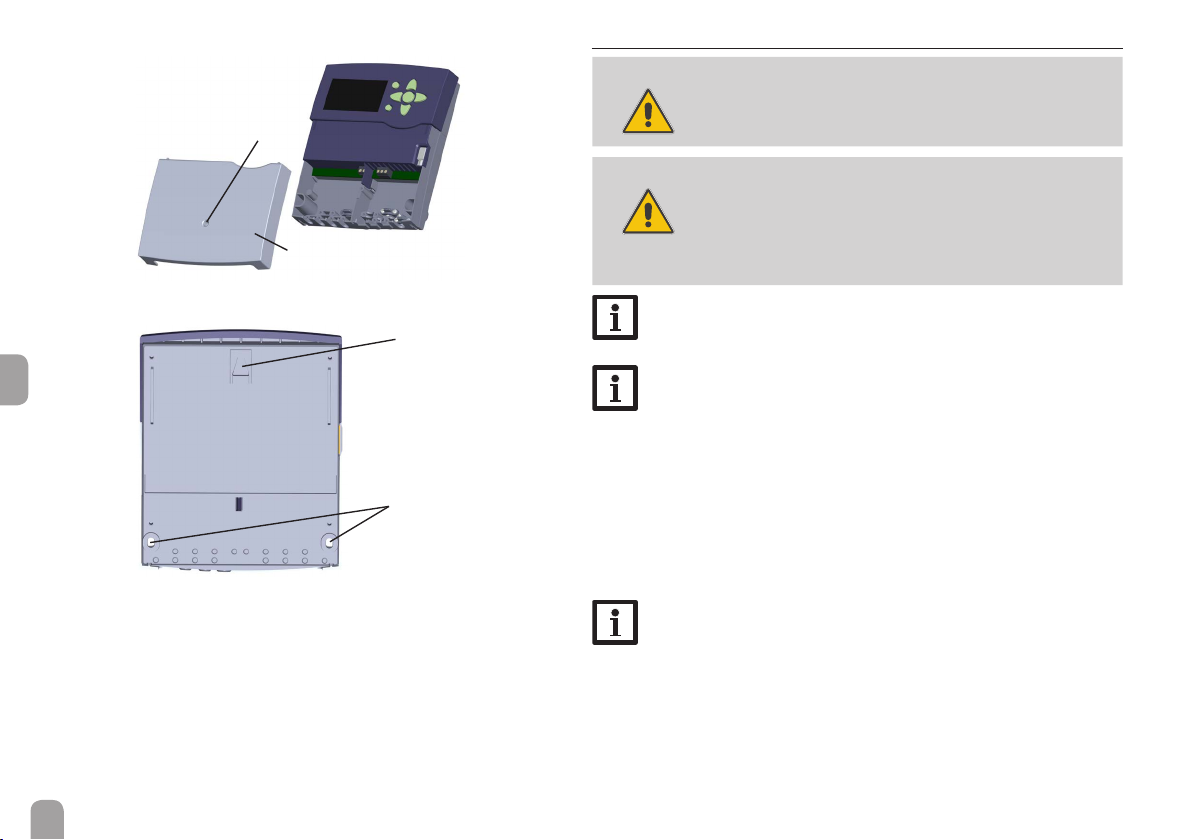
2.1 Mounting .........................................................................................................................5
2.2 Electrical connection ....................................................................................................6
2.3 Data communication / Bus ...........................................................................................7
2.4 SD memory card slot ...................................................................................................7
3 Step-by-step parameterisation ...........................................................8
4 Operation and function .......................................................................9
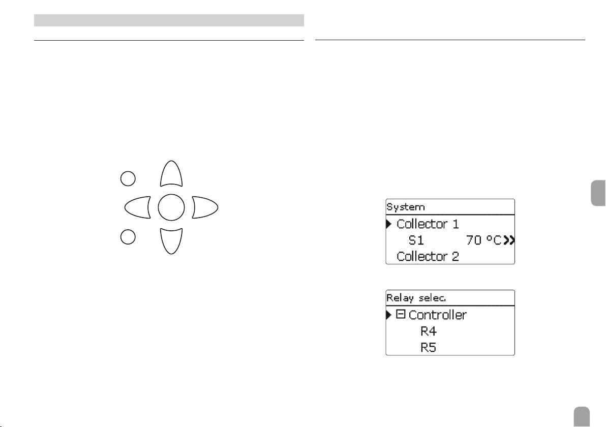
4.1 Buttons ............................................................................................................................9
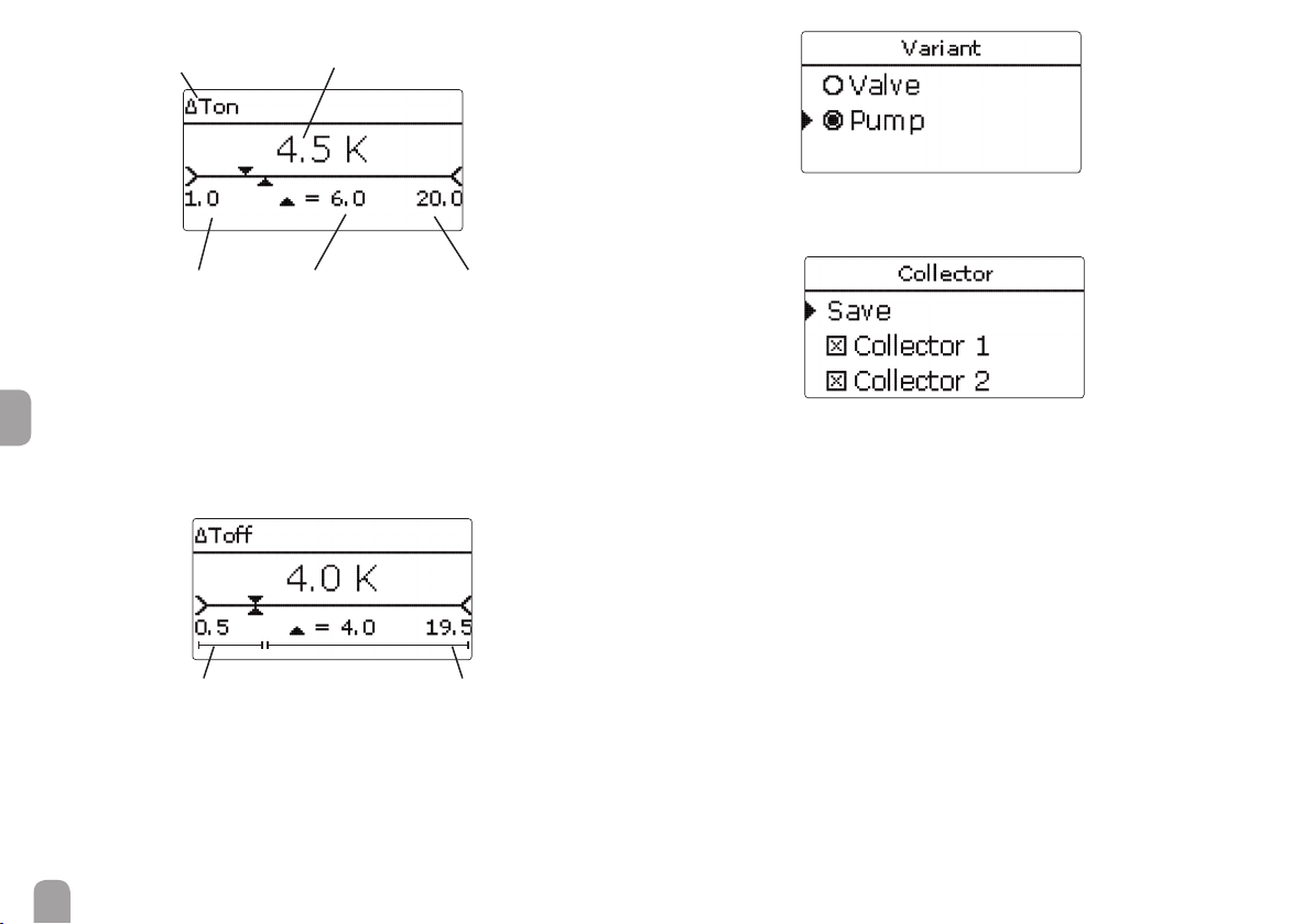
4.2 Selecting menu points and adjusting values .............................................................9
4.3 Menu structure ........................................................................................................... 13
5 Commissioning...................................................................................14
5.1 Basic systems and hydraulic variants ...................................................................... 16
5.2 Overview of relay and sensor allocation .............................................................. 17
6 Main menu ..........................................................................................27
7 Status...................................................................................................27
7.1 Solar .............................................................................................................................. 27
7.2 Arrangement ............................................................................................................... 27
7.3 Heating .......................................................................................................................... 27
7.4 Messages ....................................................................................................................... 28
7.5 Meas. / Balance values ................................................................................................. 29
7.6 Service .......................................................................................................................... 29
8 Solar.....................................................................................................29
8.1 Basic solar settings ..................................................................................................... 30
8.2 Solar optional functions ............................................................................................ 32
8.3 Function control ......................................................................................................... 43
8.4 Solar expert menu ..................................................................................................... 44
9 Arrangement ......................................................................................45
9.1 Optional functions ..................................................................................................... 45
10 Heating................................................................................................54
10.1 Demands ...................................................................................................................... 54
10.2 Heating circuits (with EM Extension Modules only) .......................................... 56
10.3 Optional functions ..................................................................................................... 59
10.4 Screed drying ............................................................................................................... 62
11 HQM ....................................................................................................63
12 Basic settings ......................................................................................65
13 SD card................................................................................................65
14 Manual mode ......................................................................................66
15 User code ............................................................................................67
16 In- / Outputs.........................................................................................67
16.1 Modules ........................................................................................................................ 67
16.2 Inputs ............................................................................................................................. 68
16.3 Outputs ........................................................................................................................ 69
16.4 VBus .............................................................................................................................. 70
17 Troubleshooting..................................................................................71
18 Accessories .........................................................................................74
18.1 Sensors and measuring instruments ...................................................................... 75
18.2 VBus® accessories ...................................................................................................... 75
18.3 Interface adapters ....................................................................................................... 76
19 Index ....................................................................................................77
The BW/H Komfort HE is a system controller for multi-store solar and heating
systems.
The intuitive commissioning menu leads you through the system conguration by
requiring the most important adjustments directly after connecting the controller.
For an optimum overview, all sensor and relay allocations are listed in the service
menu.
Contents

4
en
1 Overview
• 8 sensor inputs and 5 relay outputs
• Data logging, storing and rmware updates via SD memory card
• Pre-programmed optional functions such as: drainback option,
time-controlled thermostat function, thermal disinfection
• Up to 2 extension modules viaVBus®connectable (21 sensors and 15
relays in total)
• 2 inputs for digital Grundfos Direct Sensors™
• 2 PWM outputs for speed control of high-efciency pumps
• Automatic function control according to VDI 2169: ow rate and
pressure monitoring, warnings for too high ∆T values, interchanged
ow and return pipes and night circulation
Technical data
Inputs: 8 (9) inputs for Pt1000, Pt500, or KTY temperature sensors, 1 V40 impulse
input, inputs for 2 digital Grundfos Direct Sensors™, 1 input for a CS10 irradiation
sensor
Outputs: 4 semiconductor relays, 1 potential-free relay, 2 PWM outputs (switch-
able to 0-10 V)
Switching capacity:
1 (1) A 240 V~ (semiconductor relay)
4 (1) A 24 V / 240 V~ (potential-free relay)
Total switching capacity: 4 A 240 V~
Power supply: 100 … 240 V~ (50 … 60 Hz)
Supply connection: type Y attachment
Standby: 0,81 W
Temperature controls class: I
Energy efciency contribution: 1 %
Mode of operation: Type 1.B.C.Y
Rated impulse voltage: 2.5 kV
Data interface: VBus®, SD card slot
VBus®current supply: 60 mA
Functions: ∆T control, pump speed control, heat quantity measurement, operat-
ing hours counter for the relays, tube collector function, thermostat function, store
loading in layers, priority logic, drainback option, booster function, heat dump func-
tion, thermal disinfection function, PWM pump control, function control according
to VDI 2169 guidelines.
Housing: plastic, PC-ABS and PMMA
Mounting: wall mounting, also suitable for mounting into patch panels
Indication / Display: full graphic display, control lamp (directional pad) and back-
ground illumination
Operation: 7 push buttons at the front of the housing
Protection type: IP 20 / DIN EN 60529
Protection class: I
Ambient temperature: 0 … 40 °C
Degree of pollution: 2
Dimensions: 198 x 170 x 43 mm
170
198
43

5
en
1.1 Optional functions
Solar
Bypass
CS-Bypass
External heat exchanger
Tube collector
Target temperature
Frost protection
Backup heating suppression
Parallel relay
Cooling mode
Drainback
Twin pump
Heat dump
Flow rate monitoring
Pressure monitoring
Arrangement
Parallel relay
Mixer
Store loading
Error relay
Heat exchange
Solid fuel boiler
Circulation
Return preheating
Function block
Irradiation switch
Heating
Thermal disinfection
DHW heating
2 Installation
2.1 Mounting
WARNING! Electric shock!
Upon opening the housing, live parts are exposed!
ÎAlways disconnect the controller from power supply
before opening the housing!
Note:
Strong electromagnetic elds can impair the function of the device.
ÎMake sure the device as well as the system are not exposed to strong
electromagnetic elds.
The unit must only be located in dry interior rooms.
The device must additionally be supplied from a double pole switch with contact
gap of at least 3 mm.
Please pay attention to separate routing of sensor cables and mains cables.
In order to mount the device to the wall, carry out the following steps:
ÎUnscrew the crosshead screw from the cover and remove it along with the
cover from the housing.
ÎMark the upper fastening point on the wall. Drill and fasten the enclosed wall
plug and screw leaving the head protruding.
ÎHang the housing from the upper fastening point and mark the lower fastening
points (centres 150 mm).
ÎInsert lower wall plugs.
ÎFasten the housing to the wall with the lower fastening screw and tighten.
ÎCarry out the electrical wiring in accordance with the terminal allocation (see
page 6).
ÎPut the cover on the housing.
ÎAttach with the fastening screw.

6
en
2.2 Electrical connection
WARNING! Electric shock!
Upon opening the housing, live parts are exposed!
ÎAlways disconnect the controller from power supply
before opening the housing!
ATTENTION! ESD damage!
Electrostatic discharge can lead to damage to electronic
components!
ÎTake care to discharge properly before touching
the inside of the device!To do so, touch a grounded
surface such as a radiator or tap!
Note:
Connecting the device to the power supply must always be the last step
of the installation!
Note:
The pump speed must be set to 100 % when auxiliary relays or valves
are connected.
The controller is equipped with 5 relays in total to which loads such as pumps,
valves, etc. can be connected:
Relays 1 … 4 are semiconductor relays, designed for pump speed control:
Conductor R1 … R4
Neutral conductor N (common terminal block)
Protective earth conductor ⏚ (common terminal block)
Relay 5 is a potential-free relay:
Connections to the R5 terminals can be made with either polarity.
Note:
For more details about the commissioning procedure see page 14.
Depending on the product version, mains cables and sensor cables are already
connected to the device. If that is not the case, please proceed as follows:
Temperature sensors (S1 to S9) have to be connected to the terminals S1 to S9
and GND (either polarity). The terminal S9 can be used as an impulse input for V40
owmeters or as an input for FS08 ow switches.
A V40 owmeter can be connected to the terminals S9 / V40 and GND (either
polarity).
upper fastening point
lower fastening point
cover
screw

7
en
Connect the irradiation sensor CS10 to the terminals CS10 with correct polarity.
To do so, connect the cable marked GND to the GND common terminal block,
the cable marked CS to the terminal marked CS10.
The terminals marked PWM/0-10 V contain the 2 PWM / 0-10 V speed control
signal outputs for high-efciency pumps.
Connect the digital Grundfos Direct Sensors™ to the VFD and / or RPD in-
puts.
The controller is supplied with power via a mains cable. The power supply of the
device must be 100 … 240 V~ (50 … 60 Hz).
The mains connection is at the terminals:
Neutral conductor N
Conductor L
Protective earth conductor ⏚ (common terminal block)
WARNING! Electric shock!
L' is a fused contact permanently carrying voltage.
ÎAlways disconnect the controller from power supply
before opening the housing!
Conductor L' (L' is not connected with the mains cable. L' is a fused contact per-
manently carrying voltage)
potential-free relay
protective conductor
common terminal
block (PE)
neutral conductor
common terminal
block
VBus®
PWM / 0-10 V
connection
VBus
GND
2.3 Data communication / Bus
The controller is equipped with a VBus® for data transfer and energy supply to
external modules. The connection is to be carried out at the two terminals marked
VBus (any polarity).
One or more VBus® modules can be connected via this data bus, such as:
• DL2 Datalogger
• DL3 Datalogger
• KM1 Communication module
Furthermore, the controller can be connected to a PC or integrated into a net-
work via the VBus®/USB or VBus®/LAN interface adapter (not included).
On the website, rmware updates are also availabe.
Note:
More accessories on page 74.
2.4 SD memory card slot
The controller is equipped with an SD card slot.
With an SD card, the following functions can be carried out:
• Store measurement and balance values onto the SD card. After the
transfer to a computer, the values can be opened and visualised,
e. g. in a spreadsheet.
• Prepare adjustments and parameterisations on a computer and
transfer them via the SD card.
• Store adjustments and parameterisations on the SD card and, if necessary, re-
trieve them from there.
• Download rmware updates from the Internet and install them on the controller.
Note:
An SD memory card with up to 32 GB memory capacity can be used.
A standard SD card is not included, but can be purchased from the manufacturer.
For more information about using an SD card, see page 65.
sensor terminals
Sensor ground common
terminal block

8
en
3 Step-by-step parameterisation
The BW/H Komfort HE is a controller that offers a broad variety of functions to
the user. At the same time, the user has a lot of freedom in congurating them.
Therefore, to set up a complex system, careful planning is required. We recommend
drawing a sketch of the system rst.
If planning, hydraulic construction and electrical connection have all been carried
out successfully, proceed as follows:
1. Running the commissioning menu
The commissioning menu is run after the rst connection and after every reset. It
will request the following basic adjustments:
• Menu language
• Temperature unit
• Volume unit
• Pressure unit
• Energy unit
• Time
• Date
• Solar system
• Hydraulic variant
At the end of the commissioning menu, a safety enquiry follows. If the safety en-
quiry is conrmed, the adjustments are saved.
For further information about the commissioning menu see page 14.
2. Registering sensors
If owmeters, Grundfos Direct Sensors™ and/or external extension modules are
connected, these have to be registered in the In-/Outputs menu.
For further information about the registration of modules and sensors see page
67.
3. Activating solar optional functions
The basic solar system has been adjusted during commissioning. Now, optional
functions can be selected, activated and adjusted.
Free relays can be allocated to optional functions which require a relay. The con-
troller always suggests the numerically smallest free relay.
Sensors can be allocated to more than one function.
For further information about the solar optional functions see page 32.
4. Activating optional arrangement functions
Now, optional functions for the non-solar part of the arrangement can be selected,
activated and adjusted.
Free relays can be allocated to optional functions which require a relay. The con-
troller always suggests the numerically smallest free relay.
Sensors can be allocated to more than one function.
For further information about the optional arrangement functions see page 45.
5. Adjusting heating circuits and activating optional heating functions
Now, heating circuits can be activated and adjusted.
For the heating part of the arrangement, optional functions can be selected, acti-
vated and adjusted.
To heating circuits and optional functions which require one or more relays, the
corresponding number of free relays can be allocated. The controller always sug-
gests the numerically smallest free relay.
Sensors can be allocated to more than one function.
For further information about heating circuits and optional heating functions see
page 59.

9
en
4 Operation and function
4.1 Buttons
The controller is operated via the 7 buttons next to the display:
Button ❶ - scrolling upwards
Button ❸ - scrolling downwards
Button ❷ - increasing adjustment values
Button ❹ - reducing adjustment values
Button ➄ - con rming
Button ➅ - entering the status menu / chimney sweeper mode (system-depend-
ent)
Button ➆ - escape button for changing into the previous menu
1
2
4
63
5
7
4.2 Selecting menu points and adjusting values
During normal operation of the controller, the display is in the main menu. If no
button is pressed for 1 min, the display illumination goes out. After 3 more minutes,
the controller switches to the Status menu.
Press any key to reactivate the display illumination.
ÎIn order to get from the Status menu into the Main menu, press button ➆!
ÎIn order to scroll though a menu or to adjust a value, press either buttons ❶
and ❸ or buttons ❷ and ❹
ÎTo open a sub-menu or to con rm a value, press button ➄
ÎTo enter the status menu, press button ➅ – uncon rmed adjustment will not
be saved
ÎTo enter the previous menu, press button ➆ – uncon rmed adjustments will
not be saved
If no button has been pressed within a couple of minutes, the adjustment is can-
celled and the previous value is retained.
If the symbol ⏩ is shown behind a menu item, pressing button ➄ will open a new
sub-menu.
If the symbol ➕ is shown in front of a menu item, pressing button ➄ will open a
new sub-menu. If it is already opened, a ➖ is shown instead of the ➕.

10
en
Values and adjustments can be changed in different ways:
Numeric values can be adjusted by means of a slide bar. The minimum value is
indicated to the left, the maximum value to the right. The large number above the
slide bar indicates the current adjustment. By pressing buttons ❷ or ❹ the upper
slide bar can be moved to the left or to the right.
Only after the adjustment has been con rmed by pressing button ➄ will the num-
ber below the slide bar indicate the new value. The new value will be saved if it is
con rmed by pressing button ➄ again.
current value savedminimum value maximum value
adjusted value
(not yet con rmed)
Adjustment channel
When 2 values are locked against each other, they will display a reduced adjustment
range depending on the adjustment of the respective other value.
In this case, the active area of the slide bar is shortened, the inactive area is indicat-
ed as a dotted line. The indication of the minimum and maximum values will adapt
to the reduction.
active area inactive area
If only one item of several can be selected, they will be indicated with "radio but-
tons". When one item has been selected, the radio button in front of it is lled.
If more than one item of several can be selected, they will be indicated with check-
boxes. When an item has been selected, an x appears inside the checkbox.

11
en
Adjusting the timer
When the Timer option is activated, a timer is indicated in which time frames for
the function can be adjusted.
First of all, an overview of the current adjustments is displayed. For each day of
the week there is an overview display. The display can be switched back and forth
between the different days by pressing buttons ❷ or ❹.
In order to adjust the timer, press button ➄.
First the individual days of the week or all days of the week can be selected.
The last menu item after the list of days is Continue. If Continue is selected, the
Edit timer menu opens, in which the time frames can be adjusted.
Adding a time frame:
The time frames can be adjusted in steps of
15 min.
In order to add a time frame, proceed as fol-
lows:
ÎMove the cursor to the desired start-
ing point of the time frame by pressing
buttons ❷ and ❹. Con rm the start-
ing point of the time frame by pressing
button ❶.
ÎMove the cursor to the desired ending
point of the time frame by pressing but-
tons ❷ and ❹.
ÎThe end of a time frame can be deter-
mined by pressing button ➄.
ÎIn order to add another time frame, re-
peat the previous steps.
ÎPress button ➄ again to get back to the
overview of current adjustments.

12
en
Removing a time frame:
In order to delete a time frame, proceed as
follows:
ÎDetermine the point from which on the
time frame is to be removed by pressing
button ❸.
ÎMove the cursor to the desired ending
point of the time frame by pressing but-
tons ❷ and ❹.
ÎIn order to conclude removing the time
frame, press button ➄ upon reaching
the desired ending point.
ÎPress button ➄ again to get back to the
overview of current adjustments.

13
en
4.3 Menu structure
Main menu
Status
Solar
Arrangement
Heating
HQM
Basic settings
SD card
Manual mode
User code
In- / Outputs
Expert
Solar
Basic setting
Optional functions
Function control
Expert
Arrangement
Optional functions
Basic setting
System
Collector
Store
Loading logic
Optional functions
Parallel relay
Mixer
Store loading
Error relay
…
Heating
Demands
Heating circuits
Optional functions
Parallel relay
Relay
Reference relay
Overrun
Delay
Inverted
…
The menu items and adjustment values selectable are variable depending on adjust-
ments already made. The gure only shows an exemplary excerpt of the complete
menu in order to visualise the menu structure.
Basic settings
Language
Auto DST
Date
Time
Temp. unit
Vol. unit
…
In- / Outputs
Modules
Inputs
Outputs
VBus

14
en
5 Commissioning
When the hydraulic system is lled and ready for operation, connect the controller
to the mains.
The controller runs an initialisation phase in which the directional pad ashes red.
When the controller is commissioned or when it is reset, it will run a commis-
sioning menu after the initialisation phase. The commissioning menu leads the user
through the most important adjustment channels needed for operating the system.
Commissioning menu
The commissioning menu consists of the channels described in the following. In or-
der to make an adjustment, push button ➄. Adjust the value by pressing buttons ❹
and ❷, then push button ➄ to con rm. The next channel will appear in the display.
5
5
Adjustment mode
Button navigation
Changing a value
Con rming a value
Next parameter
2
4
1. Language:
ÎAdjust the desired menu language.
2. Scheme:
ÎCon rm the system scheme number
000.
3. Units:
ÎAdjust the desired temperature unit.
ÎAdjust the desired volume unit.
ÎAdjust the desired pressure unit.

15
en
ÎAdjust the desired energy unit.
5. Time:
ÎAdjust the clock time. First of all adjust
the hours, then the minutes.
6. Date:
ÎAdjust the date. First of all adjust the
year, then the month and then the day.
4. Daylight savings time adjustment:
ÎActivate or deactivate the automatic
daylight savings time adjustment. 8. Completing the commissioning menu:
After the system has been selected, a security enquiry appears. If the safety enquiry
is con rmed, the adjustments are saved.
ÎIn order to con rm the security enquiry, press button ➄.
ÎIn order to reenter the commissioning menu channels, press button ➆. If the
security enquiry has been con rmed, the controller is ready for operation and
should enable an optimum system operation.
Note:
The adjustments carried out during commissioning can be changed any-
time in the corresponding adjustment channel. Additional functions and
options can also be activated or deactivated.
Set the code to the customer code before handing over the con-
troller to the customer (see page 67).
7. Selection of the solar system:
ÎAdjust the desired solar system (num-
ber of collectors and stores, hydraulic
variants).

16
en
5.1 Basic systems and hydraulic variants
System
The controller is preprogrammed for 7 basic systems. The selection depends on
the number of heat sources (collector elds) and heat sinks (stores, pool). Factory
setting is system 1.
A solar system with store charging in layers is implemented as a 2-store
system (store top = store 1; store base = store 2).
The selection of the basic solar system is one of the most important adjustments
and is thus requested already in the commissioning menu.
First, the basic system is adjusted by means of the number of stores and collectors
elds, then the hydraulic variant.
The selected system is visualised by the corresponding number of store and collec-
tor symbols. The gure to the left shows system 6 which consists of 3 stores and 2
collector elds ("east- / west collectors").
Variant
The hydraulic variant refers to the different actuators that are to be controlled.
They are visualised on the display by means of symbols, when the variant is select-
ed. The upper symbol indicates the actuator belonging to the collector elds, the
lower one the actuators belonging to the stores.
The exemplary gure shows the display indicated when system 6, variant 2 has
been selected. In this case, each collector eld has a 2-port valve, the stores are
loaded by means of pump logic.
For each variant, the controller allocates the corresponding relays and sensors. The
allocations of all combinations are shown in chap. 5.2.
System 0: no solar system
System 1: 1 collector eld - 1 store
System 2: east- / west collectors - 1 store
System 3: 1 collector eld - 2 stores
System 4: east- / west collectors - 2 stores
System 5: 1 collector eld - 3 stores
System 6: east- / west collectors - 3 stores
System 7: 1 collector eld - 4 stores

en
17
5.2 Overview of relay and sensor allocation
System 1
R1
S1
S2
Relay / sensor allocation
123456789
Relay Solar pump Optional
function
Optional
function
Optional
function
Optional
function
Sensor Collector 1 Store base Free Free Free Free Free Free Free
System 2 variant 1 S1 S6
R1 R2
S2
Relay / sensor allocation
123456789
Relay Pump coll. 1 Pump coll. 2 Optional
function
Optional
function
Optional
function
Sensor Collector 1 Store base Free Free Free Collector 2 Free Free Free

en
18
S1 S6
R1 R2
S2
R3
System 2 variant 2
Relay / sensor allocation
123456789
Relay 2PV coll. 1 2PV coll. 2 Solar pump Optional
function
Optional
function
Sensor Collector 1 Store base Free Free Free Collector 2 Free Free Free
System 3 variant 1
S1
R2
R1
S2 S4
Relay / sensor allocation
123456789
Relay Solar pump 3PV
Store 2
Optional
function
Optional
function
Optional
function
Sensor Collector Store 1 base Free Store 2 base Free Free Free Free Free

en
19
System 3 variant 2
S1
R1 R2
S4
S2
R1 R2
Relay / sensor allocation
123456789
Relay Solar pump
Store 1
Solar pump
Store 2
Optional
function
Optional
function
Optional
function
Sensor Collector Store 1 base Free Store 2 base Free Free Free Free Free
System 3 variant 3
R1
R2 R3
S2
S4
S1
Relay / sensor allocation
123456789
Relay Solar pump 2PV
Store 1
2PV
Store 2
Optional
function
Optional
function
Sensor Collector Store 1 base Free Store 2 base Free Free Free Free Free

en
20
System 4 variant 1
R1
R2 R3
S2 S4
S1 S6
Relay / sensor allocation
123456789
Relay Pump coll. 1 Pump coll. 2 3PV
Store 2
Optional
function
Optional
function
Sensor Collector 1 Store 1 base Free Store 2 base Free Collector 2 Free Free Free
System 4 variant 2
R1
R2
S1 S6
R3 R4
S4
S2
Relay / sensor allocation
123456789
Relay Pump coll. 1 Pump coll. 2 2PV
Store 1
2PV
Store 2
Optional
function
Sensor Collector 1 Store 1 base Free Store 2 base Free Collector 2 Free Free Free
Table of contents
Other Roth Controllers manuals
Popular Controllers manuals by other brands

Siemens
Siemens Simatic S7-300 Getting started

Emerson
Emerson PACSystems RSTi-EP user manual

Linak
Linak BusLink LA14 user manual

MKS
MKS 647B instruction manual

PRECISION DIGITAL
PRECISION DIGITAL Helios PD2-6310 instruction manual

Emerson
Emerson Bettis XTE3000 Installation, operation and maintenance manual