manuals.online logo
Brands
  1. Home
  2. •
  3. Brands
  4. •
  5. alre
  6. •
  7. Controllers
  8. •
  9. alre KTBSB-112.000 User manual

alre KTBSB-112.000 User manual

KTBSB-112.000
Stand 02.2020 (20/024) 4 12 676 01
Klimaregler „Heizen oder Kühlen“ für Fancoil-Geräte oder Teilklimaanlagen mit Heiz-/Kühlumschaltung im 4-Rohrsystem
Heating / cooling climate controller with heating / cooling changeover contact for use with four-pipe fancoil or partial air conditioning systems
Régulateur climatique du type «chauffage / refroidissement» avec contact à permutation «chauffage / refroidissement» pour l’utilisation avec des
systèmes à ventilo-convecteurs ou des systèmes de climatisation partielle à 4 conduites
Regolatore climatico „riscaldamento o raffreddamento“ per unità fancoil o impianti di condizionamento parziale con
commutazione riscaldamento/raffreddamento e posizione centrale senza contatto in un sistema a 4 tubi
Regulátor klimatizace „Topení nebo chlazení“ pro přístroje Fancoil nebo částečné klimatizace s přepínáním na topení nebo chlazení a bezkon-
taktním nastavení střední polohy v 4 potrubního systému
Sterownik klimatyzacji „Ogrzewanie lub chłodzenie” dla klimakonwektorów lub częściowych systemów klimatyzacji
z przełączaniem ogrzewanie/chłodzenie i bezdotykowym położeniem środkowym w systemie 4-rurowym
No persons other than expert electricians only must open this device in due compliance with
the related wiring diagram shown in the housing cover / on the housing / represented in the
corresponding operating instructions. All expert electricians committed to the execution of any
such works must comply with the relevant safety regulations currently operative and in force.
These operating instructions must be kept at a place that can be accessed freely by the operating
and/or servicing personnel in charge.
3. Installation/Montage
This controller has been designed for the installation on a wall surface or on an UP box. The
surface it is installed on must be non conducting. If drill holes are made into the wall in order to
install the device, care must be taken to ensure that no concealed electric lines are damaged
thereby. The special adapter plate JZ-17 enables to mount the device directly on an UP box. If
mounting it on an UP box that is installed in a hollow or cavity wall, both the UP box and the cable
feed-throughs behind the device need to sealed up against draughts. If otherwise, the actually
acquired room temperature data could be or become incorrect. The device must not be exposed
directly to any heat- or cold sources whatsoever.
Caution: The controller described herein is able to resist to the types of dirt or dust that normally
occur in offices and living spaces. Excessive volumes of dust and/or dirt produced during the
installation or during renovation works may soil the contacts and can lead to a breakdown of the
device. In any such case, the contacts need to be cleaned by an expert electrician. This may for
example be effected by blowing the device down or by cleaning it with a dry brush.
3. Mounting / Installation
Sicherheitshinweis! D Safety information! GB
Dieses Gerät darf nur durch eine Elektrofachkraft geöffnet und gemäß dem entsprechenden
Schaltbild im Gehäusedeckel / auf dem Gehäuse / in der Bedienungsanleitung installiert werden.
Dabei sind die bestehenden Sicherheitsvorschriften zubeachten.
Die Bedienungsanleitung muss für Bedien- und Wartungspersonal an frei zugänglicher Stelle
aufbewahrt werden.
Der Regler ist zur Montage auf die Wand oder auf eine UP-Dose bestimmt. Der Untergrund darf
nicht leitend sein. Erfolgt die Montage mittels Bohrungen in die Wand, ist darauf zu achten, die
unter Putz verlegten elektrischen Leitungen nicht zu beschädigen. Für die direkte Montage des
Reglers auf eine UP-Dose wird die Adapterplatte JZ-17 verwendet. Bei Holwänden müssen die
Unterputzdose und Durchführungen hinter dem Regler gegen Zugluft abgedichtet werden, um
die Raumtemperaturerfassung nicht zu verfälschen. Der Regler darf nicht direkt Wärme- oder
Kältequellen ausgesetzt werden.
Achtung: Der Regler ist für übliche Verunreinigungen in Wohn- und Büroräumen geeignet.
Unverhältnismäßiger Schmutz und Staub während der Installations- oder Renovierungsarbeiten
kann die Kontakte verschmutzen und zum Ausfall des Reglers führen. In diesem Fall sind die
Kontakte von einer Elektrofachkraft zu reinigen. Dies kann zum Beispiel durch Ausblasen oder
durch reinigen mit einem trockenen Pinsel geschehen.
1. Anwendung
Dieser Klimaregler wurde speziell zur Ansteuerung von Fancoil und Teilklimaanlagen in
4-Rohrsystem-ausführung für Hotel-, Wohn- und Geschäftsräume entwickelt. Für andere vom
Hersteller nicht vorherzusehende Einsatzgebiete sind die dort gültigen Sicherheitsnormen zu
beachten. Eignung hierfür siehe Punkt 10. Gewährleistung.
This climate controller has been specially devised for the excitation and control of four-pipe
fancoil and partial air conditioning system operated in business premises, hotel rooms and living
spaces. Regarding other applications not to be foreseen by the manufacturer of this device, the
safety standards concerning these applications need to be followed and adhered to. Regarding the
aptitude of the device for any such other application, please refer to section 10. herein (Warranty).
1. Application
2. Funktion
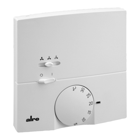
The KTBSB-112.000 is equipped with 2 switches that enable to activate it and to select the required
fan stage. The device is furnished with a changeover contact without neutral zone. This is why
heat and cold must not be provided with regard to the room to be controlled. Changeover between
heating and cooling must be effected externally through the related air conditioning system.
Thermal recirculation
The thermal recirculation realised with this device enables to excite it early enough with the
consequence that a very precise switching difference can be attained. This device has been
specially dimensioned for the control of climates prevailing in rooms within which the temperature
change rate does not exceed 4K per hour. Higher change rates could result in higher switching
differences.
Range suppression
The setting pins located underneath of the knob enable to delimit the setting range mechanically.
2. Functional description
4. Technische Daten 4. Technical data
Der KTBSB-112.000 verfügt über 2 Schalter mit denen der Regler in Betrieb genommen und die
Lüfter-stufe gewählt werden. Der Regler verfügt über einen Umschaltkontakt ohne Neutrale Zone.
Daher darf für den zu regelnden Raum nicht gleichzeitig Wärme und Kälte bereitgestellt werden.
Die Heiz-/Kühlumschaltung muss extern durch die Klimaanlage erfolgen.
Thermische Rückführung
Durch die thermische Rückführung wird der Regler rechtzeitig zum Ausschalten angeregt,
wodurch sehr kleine Schaltdifferenzen erreicht werden. Dieser Klimaregler ist für Räume mit
einer maximalen Raumtemperatur-Änderungsgeschwindigkeit von 4K/h ausgelegt. Höhere
Änderungsgeschwindigkeiten können zu größeren Schaltdifferenzen führen.
Bereichseinengung
Der Einstellbereich kann mechanisch unter dem Knopf mit den Einstellfahnen begrenzt werden.
Fühlerelement: Bimetall, Umschalter
Wirkungsweise: Typ 1C
Schaltdifferenz: ca. 0,5 K
Regelbereiche: +5 … +30°C
Schaltvermögen: 250 V~, 6(3)A, max.10 Stellantriebe je Ausgang
Schutzart: IP30 nach entsprechender Montage
Schutzklasse: II nach entsprechender Montage
Max. Luftfeuchtigkeit: 95%rH, nicht kondensierend
Gehäusedesign: Berlin 3000
Material und Farbe: Kunststoff ABS, alpinweiß (ähnlich RAL 9010)
Verschmutzungsgrad: 2
Bemessungsstoßspannung: 4000 V
Energieeffizienzklasse: I (Beitrag zur jahreszeitbedingten Raumheizungs-
Energieeffizienz 1%)
Temperatur der Kugeldruckprüfung: 75°C
Sensing element: bimetal sensor / changeover contact
Mode of operation: Type 1C
Switching difference: approx. 0.5 K
Control range: +5 … +30°C
Switching capacity: 250 V~, 6(3)A (no more than 10 actuators per outlet)
Degree of protection: IP30 (after according installation)
Protection class: II (after according installation)
Max. admissible air moisture: max. 95% r.h., non condensing
Housing model: Berlin 3000
Material and colour: ABS plastic, pure with (similar to RAL 9010)
Degree of contamination: 2
Rated impulse voltage: 4000 V
Energy efficiency class: I (contribution to seasonal space heating energy
efficiency 1%)
Temperature of ball indentation test: 75°C
6. Zubehör (optional) 6. Accessories (optional)
JZ-17 Adapterplatte zur direkten Befestigung des Reglers auf die UP-Dose. JZ-17 Adapter plate for direct fixing on an UP box.
5. Terminal assignment
Type: KTBSB-112.000
Terminal Symbol Assignment
1 Heating outlet
2 Cooling outlet
3 LSupply voltage phase
4 Fan (low speed)
5 Fan (medial speed)
6 Fan (fast speed)
7 NNeutral conductor (consumers)
8 NNeutral conductor (consumers)
9 NNeutral conductor (supply voltage)
5. Klemmenbelegung
Typ: KTBSB-112.000
Klemme Symbol Belegung
1 Heizausgang
2 Kühlausgang
3 LPhase Versorgungsspannung
4 Lüfter langsame Stufe
5 Lüfter mittlere Stufe
6 Lüfter schnelle Stufe
7 NNeutralleiter Verbraucher
8 NNeutralleiter Verbraucher
9 NNeutralleiter Versorgungsspannung
Consigne de sécurité! F
Uniquement des personnes qualifiées en matière d’électricité doivent ouvrir ce dispositif en
conformité avec le schéma des connexions imprimé sur le boîtier ou apposé à celui-ci ou bien
représenté dans les notices d’instructions correspondantes. Tous électriciens spécialisés chargés
de l’exécution de tels travaux doivent se conformer aux prescriptions de sécurité actuellement en
vigueur s’y rapportant.
Les instructions de service sont à garder à un lieu librement accessible pour les personnels de
service et d’entretien.
3. Installation
Le dispositif est prévu pour l’installation murale ou pour l’installation sur une boîte encastrée. La
surface utilisée pour son installation ne doit pas être conductrice. Lorsque le dispositif est installé
en perçant des trous dans le mur, il faut veiller à ce que pas de lignes électriques encastrées ne
soient endommagées lors de ceci. L’utilisation de la plaque adaptateur spéciale JZ-17 permet le
montage direct sur une boîte encastrée. Lorsque le dispositif est monté sur une boîte encastrée
qui a été installé dans un mur creux, il
faudrait que la boîte de même que les passes-câbles en
arrière du dispositif soient rendus étanches contre
des courants d’air. Car sinon, la valeur de la
température actuellement détectée pourrait être ou bien devenir incorrecte. Le dispositif ne doit
être exposé à aucunes sources de chaleur ou de froid telles qu’elles soient.
Attention: le régulateur décrit dans cette notice d’instruction ne peut résister qu’à des types de
crasses ou de poussières qui se produisent habituellement dans des bureaux ou des habitations.
Des encrassages ou des volumes de poussière plus importants se produisant durant des travaux
d’‘installation et/ou de la mise en neuf peuvent salir les contacts et provoquer une panne du
régulateur. Dans un tel cas, il faut que les contacts soient nettoyés par un électricien spécialiste.
Le nettoyage peut, par exemple, être effectué en soufflant ou par moyen d’une brosse.
1. Application
Ce régulateur climatique a été spécialement conçu pour l’excitation et le contrôle de systèmes à
ventilo-convecteurs ou des système de climatisation partielle à quatre conduites utilisés dans des
locaux à usage commercial, des salles d’hôtel et dans des habitations. Concernant des autres
applications pas à prévoir par le fabricant de ce dispositif, les standards de sécurité se rapportant
à ces applications sont à respecter. En ce qui concerne l’aptitude ou l’approbation du dispositif
pour des telles applications, veuillez également faire attention aux informations de garantie dans
chapitre 10. (Garantie) dans cette notice d’instructions.
2. Fonctionnement
4. Caractéristiques techniques
6. Accessoires (facultatif)
Le KTBSB-112.000 est muni de 2 interrupteurs qui permettent de l’activer et de sélectionner les
fonctions du ventilateur requises. Le dispositif est doté d’un contact à permutation sans zone
neutre. C’est pourquoi la chaleur et le froid ne doivent pas être délivrés simultanément dans la
salle ou pièce à régler. La com
mutation entre chauffage et refroidissement doit être effectuée de
l’extérieur par le système de climatisation
correspondant.
Recirculation thermique
La recirculation thermique réalisée avec ce dispositif permet de l’exciter assez longtemps à
l’avance pour pouvoir atteindre un différentiel très précis. Ce dispositif a été spécialement
dimensionné pour le contrôle de températures ambiantes qui prédominent dans des salles ou
pièces dans lesquelles le taux de changement de la température ne dépasse pas une valeur de
4K par heure. Des taux de changement plus élevés pourraient résulter dans des différentiels
également plus élevés.
Resserrage de domaine
La plage de réglage peut être limitée mécaniquement au moyen des éléments mobiles d’ajustage
qui se trouvent en dessous du bouton de réglage.
Capteur: bilame / contact à permutation
Mode de fonctionnement: type 1C
Différentiel: env. 0,5 K
Plage de réglage: +5 … +30°C
Pouvoir de coupure: 250 V~, 6(3)A (max.10 actionneurs par sortie)
Type de protection: IP30 (après installation correspondante)
Indice de protection: II (après installation correspondante)
Humidité de l’aire admissible: max. 95% r.h., non condensant
Modèle du boîtier: Berlin 3000
Matériau et couleur: en plastique (ABS), blanc pur (pareil à RAL 9010)
Degré de pollution: 2
Tension nominale d’impulsion: 4000 V
Classe d‘efficacité énergétique : I (contributtion à l‘efficacité énergétique du chauffage
saisonnier 1%)
Température de l’essai de billage: 75°C
JZ-17 Plaque adaptateur pour le montage direct sur une boîte encastrée
5. Occupation des bornes
Type: KTBSB-112.000
Borne Symbole Occupation
1 Sortie de chauffage
2 Sortie de refroidissement
3 LPhase de la tension d’alimentation
4 Ventilateur (vitesse faible)
5 Ventilateur (vitesse moyenne)
6 Ventilateur (vitesse élevée)
7 NConducteur neutre (consommateurs)
8 NConducteur neutre (consommateurs)
9 NConducteur neutre (tension d’alimentation)
3. Installazione/Montaggio
Informazioni per la sicurezza! I
Questo apparecchio può essere aperto solo da un elettricista qualificato e installato secondo lo
schema elettrico corrispondente nel coperchio dell'alloggiamento / sull'alloggiamento / nelle
istruzioni d'uso. Devono essere rispettate le norme di sicurezza presenti.
Le istruzioni per l'uso devono essere conservate in un luogo liberamente accessibile al personale
addetto all'uso e alla manutenzione.
Il regolatore è destinato al montaggio a parete o su una scatola da incasso. La superficie su cui
è installatonon deve essere conduttiva. Se per il montaggio vengono praticati dei fori nella parete,
occorre fare attenzione a non danneggiare le linee elettriche nascoste. La speciale piastra di
adattamento JZ-17 permette di montare il dispositivo direttamente su una scatola da incasso. Nel
caso di pareti cave, la presa a muro e i passacavi dietro il regolatore devono essere sigillati contro
le correnti d'aria per non falsificare la rilevazione della temperatura ambiente. Il regolatore non
deve essere esposto direttamente a fonti di calore o di freddo.
Attenzione: il regolatore è adatto per la normale sporcizia in ambienti abitativi e uffici. Sporcizia
e polvere sproporzionate durante i lavori di installazione o di ristrutturazione possono sporcare
i contattie causare il guasto del regolatore. In questo caso i contatti devono essere puliti da un
elettricista qualificato. Questo può essere fatto, ad esempio, soffiando o pulendo con un pennello
a secco.
1. Applicazione
Questo regolatore climatico è stato sviluppato appositamente per il controllo di fancoil e impianti
di condizionamento parziale in impianti a 4 tubi per hotel, abitazioni e locali commerciali. Per
altri campi di applicazione non prevedibili dal produttore, devono essere rispettate le norme di
sicurezza ivi applicabili. Per l'idoneità vedere il punto 10. Garanzia.
2. Funzione
4. Dati tecnici
Il KTBSB-112.000 è dotato di 2 interruttori con i quali si avvia il regolatore e si seleziona la
velocità del ventilatore. Il regolatore ha un contatto di commutazione senza zona neutra. Pertanto,
il calore e il freddo non devono essere forniti contemporaneamente per il locale da regolare. La
commutazione tra riscaldamento e raffreddamento deve essere effettuata esternamente attraverso
il relativo impianto di condizionamento.
Ricircolo termico
Il ricircolo termico stimola il regolatore a spegnersi in tempo, con conseguenti differenze di
commutazione molto piccole. Questo regolatore climatico è progettato per ambienti con un tasso
massimo di variazione della temperatura ambiente di 4K/h. Velocità di cambiamento più elevate
possono portare a maggiori differenze di commutazione.
Limitazione di campo della temperatura
Le linguette di regolazione situati sotto la manopola permettono di delimitare meccanicamente il
campo di regolazione.
Elemento sensore: bimetallo, commutatore
Modalità operativa: Tipo 1C
Differenziale di commutazione: ca. 0,5 K
Campi di regolazione: +5 … +30°C
Capacità di commutazione: 250 V~, 6(3)A, max.10 attuatori per uscita
Tipo di protezione: IP30 dopo il montaggio appropriato
Classe di protezione: II dopo il montaggio appropriato
Max. umidità: 95%rH, non condensante
Design dell'alloggiamento: Berlin 3000
Materiale e colore: plastica ABS, bianco alpino (simile a RAL 9010)
Grado di inquinamento : 2
Tensione nominale di tenuta: 4000 V
Classe di efficienza energetica: I (contributo dell‘1% di efficienza energetica per il
riscaldamento stagionale)
Temperatura prova di durezza Brinell: 75°C
6. Accessori (opzionale)
JZ-17 Piastra di adattamento per il montaggio diretto del regolatore sulla scatola da incasso.
5. Occupazione dei morsetti
Tipo: KTBSB-112.000
Morsetto Simbolo Occupazione
1 Uscita del riscaldamento
2 Uscita del raffreddamento
3 LFase tensione di alimentazione
4 Ventilatore a bassa velocità
5 Ventilatore a media velocità
6 Ventolatore a rapida velocità
7 NConduttore neutro consumatori
8 NConduttore neutro consumatori
9 NConduttore neutro tensione di alimentazione
Bezpečnostní pokyny! CZ
Tento přístroj může otevírat a instalovat v souladu s odpovídajícím schématem zapojení na
víku přístroje / na krytu / podle návodu k použití pouze elektrotechnický odborník. Přitom musí
dodržovat stávající bezpečnostní předpisy.
Návod k použití je nutné pro ovládací a servisní personál uchovávat na volně přísstupném místě.
3. Instalace/montáž
Regulátor je určen k montáži na zeď nebo do krabice pod omítku Podklad nesmí být vodivý.
Provádí-li se montáž pomocí navrtaných otvorů do zdi je třeba dbát na to, aby se nepoškodilo
elektrické vedení pod omítkou. Pro přímou montáž regulátoru do krabice pod omítku se použije
adaptační deska JZ-17. Duté stěny je třeba krabici pod omítku a vedení za regulátorem utěsnit
proti průvanu, aby nedocházelo k ovlivnění zjišťování teploty pokoje. Regulátor nesmí být přímo
vystaven působením zdrojů tepla nebo zimy.
Pozor: Regulátor je vhodný pro běžná znečištění v obytných a kancelářských prostorách.
Neobvyklé znešitění a prach během instalace nebo během oprav může vést k znečištění kontaktů
a způsobit výpadek regulátoru. V tomto případě musí kontakty očistit kvalifikovaná obsluha.
Provést to lze například ofouknutím nebo očištěním suchým štětcem.
1. Použití
Tento regulátor klimatizace byl konstruován spediálně pro použití v zařízeních Fancoil a
částečných klimatizacích ve 4 potrubních sítích pro hotelové, obytné a obchodní prostory. V
ostatních Eignung hierfür siehe Punkt 10. Záruka.
2. Funkce
4. Technické údaje
6. Příslušenství (volitelné)
KTBSB-112.000 disponuje 2 spínači pomocí kterých se regulátory aktivují a nastaví úroveň
ventilace. Regulátor má kointakt na přepínání bez neutrální zóny. Proto nelze v tepelně
regulované místnosti současně nastavit teplo i chlad. Nastavení tepla nebo chladu je proto nutné
provádět pomocí klimatizace.
Termické zpětné vedení
Termickým zpětným vedením se včas aktivuje vypínání regulátoru, čímž dochází k velmi malým
rozdílům ve spínání. Tento regulátor klimatizace je určený pro místnosti s maximální rychlostí
změny teploty místnosti 4K/h. Vyšší rychlosti změny mohou způsobit vyšší rozdíly řazení.
Omezení prostoru
Rozsah nastavení lze omezit mechanicky pomocí otočného regulátoru se symboly nastavení.
Čidlo: Bimetal, přepínač
Provozní režim: Typ 1C
Rozdíl přepínání: cca. 0,5 K
Rozsah regulace: +5 … +30°C
Možnosti přepínání: 250 V~, 6(3)A, max. 10 , na každý výstup servopohon
Druh ochrany: IP30 po odpovídající montáži
Třída ochrany: II po odpovídající montáži
Max. vlhkost vzduchu: 95%rH, nekondenzující
Design krytu: Berlin 3000
Materiál a barva: Umělá hmota ABS, bílá (podobná jako RAL 9010)
Stupeň znečištění: 2
Domezovací rázové napětí: 4000 V
Energetická třída: I (příspěvek k energetické účinnosti při sezónním
vytápění místnosti 1%)
Teplota zkoušky tlaku koule: 75°C
JZ-17 Deska adaptéru k přímému upevnění regulátoru na krabici pod omítku.
5. Obsazení svorek
Typ: KTBSB-112.000
Svorka Symbol Obsazení
1 Výstup topení
2 Výstup chlazení
3 L Fáze napájecího napětí
4 Ventilátor pomalý stupeň
5 Ventilátor střední stupeň
6 Ventilátor rychlý stupeň
7 N Neutrální vodič spotřebič
8 N Neutrální vodič spotřebič
9 N Neutrální napájecího napětí
3. Instalacja/montaż
Wskazówka dotycząca bezpieczeństwa! PL
Niniejsze urządzenie może być otwierane wyłącznie przez wykwalifikowanego elektryka
i instalowane zgodnie z odpowiednim schematem połączeń w pokrywie obudowy / na obudowie /
w instrukcji obsługi. Należy przestrzegać obowiązujących przepisów bezpieczeństwa.
Instrukcja obsługi musi być przechowywana w miejscu łatwo dostępnym dla personelu
obsługującego i konserwującego.
Sterownik jest przeznaczony do montażu na ścianie lub na puszce podtynkowej. Podłoże nie
może być przewodzące. Jeżeli instalacja jest wykonywana za pomocą otworów w ścianie,
należy zwracać uwagę, aby nie uszkodzić przewodów elektrycznych ułożonych pod tynkiem.
Do bezpośredniego montażu sterownika na puszce podtynkowej jest stosowana płyta adaptera
JZ-17. Przy ścianach szczelinowych puszka podtynkowa i przepusty za sterownikiem muszą
być uszczelnione przed przeciągami, aby nie dopuścić do sfałszowania zapisu temperatury
pomieszczenia. Sterownika nie można narażać na bezpośrednie działanie źródeł ciepła lub zimna.
Uwaga: Sterownik nadaje się do normalnych zanieczyszczeń w pomieszczeniach mieszkalnych
i biurowych. Nieproporcjonalne zabrudzenia i kurz podczas prac instalacyjnych lub remontowych
mogą zabrudzić styki i prowadzić do awarii sterownika. W takim przypadku styki muszą zostać
wyczyszczone przez wykwalifikowanego elektryka. W tym celu można przykładowo przedmuchać
sterownik lub wyczyścić go suchym pędzlem.
1. Zastosowanie
Ten sterownik klimatyzacji został opracowany specjalnie do sterowania klimakonwektorami
i częściowymi systemami klimatyzacji w wersjach 4-rurowych dla obiektów hotelowych,
mieszkalnych i biznesowych. W przypadku innych, nieprzewidzianych przez producenta zakresów
zastosowania należy przestrzegać obowiązujących w tym zakresie norm bezpieczeństwa.
Przydatność, patrz punkt 10. Gwarancja.
2. Zasada działania
4. Dane techniczne
KTBSB-112.000 posiada 2 przełączniki, za pomocą których jest uruchamiany sterownik i jest
wybierany stopień wentylatora. Sterownik posiada styk przełączny bez strefy neutralnej. Dlatego
też w regulowanym pomieszczeniu nie można jednocześnie zapewniać dopływu ciepła i zimna.
Przełączanie ciepło/zimno musi się odbywać zewnętrznie, za pomocą systemu klimatyzacji.
Recyrkulacja termiczna
Recyrkulacja termiczna stymuluje sterownik do terminowego wyłączenia, co powoduje bardzo
małe różnice przełączania. Niniejszy sterownik klimatyzacji jest przeznaczony do pomieszczeń
o maksymalnej prędkości zmiany temperatury w pomieszczeniu wynoszącej 4K/h. Wyższe
prędkości zmiany mogą powodować większe różnice przełączania.
Ograniczenie zakresu
Zakres nastawczy można ograniczyć mechanicznie pokrętłem ze sztyftami nastawczymi.
Le linguette di regolazione situati sotto la manopola permettono di delimitare meccanicamente il
campo di regolazione.
Element czujnikowy: Bimetal, przełącznik
Tryb działania: Typu 1C
Różnica przełączania: ok. 0,5 K
Zakresy regulacji: +5 … +30°C
Zdolność łączenia: 250 V~, 6(3)A, maks. 10 organów wykonawczych
na wyjście
Stopień ochrony: IP30 po odpowiednim montażu
Klasa ochrony: II po odpowiednim montażu
Maks. wilgotność powietrza: 95% względnej wilgotności powietrza, bez
skondensowania
Konstrukcja obudowy: Berlin 3000
Materiał i kolor: Tworzywo sztuczne ABS, biały alpejski
(podobny do RAL 9010)
Stopień zanieczyszczenia: 2
Pomiarowe napięcie udarowe: 4000 V
Klasa efektywności energetycznej: I (wkład w efektywność energetyczną sezonowego
ogrzewania pomieszczeń 1%)
Temperatura kontroli ciśnienia kulkowego: 75°C
6. Akcesoria (opcjonalne)
JZ-17 Płyta adaptera do bezpośredniego montażu sterownika na puszce podtynkowej.
5. Przyporządkowanie zacisków
Typ: KTBSB-112.000
Zacisk Symbol Przyporządkowanie
1 Wyjście ogrzewania
2 Wyjście chłodzenia
3 L Faza napięcia zasilania
4 Wentylator, poziom wolny
5 Wentylator, poziom średni
6 Wentylator, poziom szybki
7 N Przewód zerowy odbiornika
8 N Przewód zerowy odbiornika
9 N Przewód zerowy napięcia zasilania
Die angegebenen technischen Daten wurden durch uns jeweils in einem dafür geeigneten Prüf- und Testumfeld (hierzu geben wir auf Anfrage Auskunft) ermittelt und stellen nur auf dieser Grundlage
die vereinbarte Beschaffenheit dar. Die Prüfung der Eignung für den vom Auftraggeber / Kunden vorgesehenen Verwendungszweck oder den Einsatz unter den konkreten Gebrauchsbedingungen
obliegt dem Auftraggeber / Kunden; hierfür übernehmen wir keine Gewährleistung. Änderungen vorbehalten.
We determined the technical data provided in an inspection and test environment suited to this task (we are happy to provide details on request) and this data only presents the agreed properties on this
basis. The purchaser / customer is responsible for checking the suitability of the use or usage intended by the purchaser / customer under the specific conditions of use; we do not accept any liability for
this. We reserve the right to amendments.
Les caractéristiques techniques indiquées ont été définies par nos soins respectivement dans un environnement de contrôle et de test approprié (possibilité de vous faire parvenir des informations sur
demande) et constituent uniquement sur cette base la qualité convenue. Le contrôle de conformité à l’usage prévu par le donneur d’ordre / le client ou à l’usage dans des conditions d’utilisation concrètes
incombe au donneur d‘ordre / au client ; nous déclinons à ce sujet toute garantie. Sous réserve de modifications.
I dati tecnici indicati sono stati da noi rilevati in un ambiente di prova e di test adeguato a tale scopo (maggiori informazioni su richiesta) e presentano le caratteristiche stabilite solamente sulla base
delle suddette condizioni. La verifica di idoneità per lo scopo di destinazione previsto dal committente / cliente oppure per l’impiego in concrete condizioni di servizio è a carico del committente / cliente.
La nostra azienda non si assume alcuna garanzia al riguardo. Salvo modifiche.
Uvedené technické údaje byly stanoveny námi ve vhodném zkušebním a zkušebním prostředí (můžeme poskytnout informace na vyžádání) a na tomto základě představují pouze dohodnutou kvalitu,
za použití za zvláštních podmínek použití odpovídá zákazník. nezaručujeme to. Změny vyhrazeny.
Przedstawiane dane techniczne są ustalane przez nas każdorazowo na podstawie właściwego zakresu badań i testów (informacji udzielamy na życzenie) i przedstawiają wyłącznie cechy ustalone na
ich podstawie. Kontrola przydatności w zakresie przewidzianym przez zleceniodawcę/ klienta lub do zastosowania w konkretnych warunkach użytkowania jest zadaniem zleceniodawcy/ klienta; nie
udzielamy żadnych gwarancji w tym zakresie. Zmiany techniczne zastrzeżone.
ALRE-IT Regeltechnik GmbH · Richard-Tauber-Damm 10 · D-12277 Berlin
Tel.: +49(0)30/399 84-0 · Fax: +49(0)30/39170 05 · [email protected] · www.alre.de
10. Gewährleistung / Warranty / Garantie / Garanzia / Garance / Gwarancja
Einstellfahne
für maximalen
Temperaturwert
Pin for the
setting of the
maximum
temperature value
Broche pour
l’ajustage de la
valeur de
température
maximale
Linguetta di
regolazione
per la regolazione
del valore
massimo di
temperatura
Symboly
nastavení
pro maximální
hodnotu teplotu
Sztyft nastawczy
dla maks.
wart. temperatury
Einstellfahne
für minimalen
Temperaturwert
Pin for the
setting of the
minimum
temperature value
Broche pour
l’ajustage de la
valeur de
température
minimale
Linguetta di
regolzione
per la regolazione
del valore minimo
di temperatura.
Symbol nastavení
pro minimální
hodnotu teploty
Sztyft nastawczy
dla min.
wart. temperatury
7. Installationshinweise / Installation information / Informations d’installation / Informazioni per l‘installazione / Pokyny
pro instalaci / Wskazówki instalacyjne
8. Maßbild und Anschluss-Schaltbild / Dimensioned drawing and connection scheme / Dessin coté et schéma
de branchement / Disegno dimensionale e schema di collegamento / Schéma rozměrů a nastavení / Rysunek
wymiarowy ze schematem połączeń
9. Montagehinweis / Mounting information / Précision d’installation / Informazioni per il montaggio / Montážní pokyny /
Wskazówka montażowa

This manual suits for next models

1

Other alre Controllers manuals

alre KR 80 Series User manual

alre

alre KR 80 Series User manual

alre HTFRD Series User manual

alre

alre HTFRD Series User manual

alre KTRTB-211.108 User manual

alre

alre KTRTB-211.108 User manual

alre KTRRB-042.211 User manual

alre

alre KTRRB-042.211 User manual

alre KTRBUu217.456 User manual

alre

alre KTRBUu217.456 User manual

alre CTRRS-161.000 User manual

alre

alre CTRRS-161.000 User manual

alre KTRRU-052.204 User manual

alre

alre KTRRU-052.204 User manual

alre KTRRB-117.128 User manual

alre

alre KTRRB-117.128 User manual

alre FETR 101.700 User manual

alre

alre FETR 101.700 User manual

alre KTRTB-251.108 User manual

alre

alre KTRTB-251.108 User manual

alre RFHSB-060.010 User manual

alre

alre RFHSB-060.010 User manual

alre JDI-22 Instruction manual

alre

alre JDI-22 Instruction manual

alre KTRRN-267.014 User manual

alre

alre KTRRN-267.014 User manual

Popular Controllers manuals by other brands

PTI SENTRY 1510 Operation & installation manual

PTI

PTI SENTRY 1510 Operation & installation manual

IBM Netfinity ServeRAID-4H Ultra160 User reference

IBM

IBM Netfinity ServeRAID-4H Ultra160 User reference

Rain Bird 9V-2 Technotes

Rain Bird

Rain Bird 9V-2 Technotes

Smartgen HAT600N Series user manual

Smartgen

Smartgen HAT600N Series user manual

Elan HC6 Quick install guide

Elan

Elan HC6 Quick install guide

IRIS ID IrisAcces ICU7000-2 Hardware guide

IRIS ID

IRIS ID IrisAcces ICU7000-2 Hardware guide

Crestron MC2W Operation guide

Crestron

Crestron MC2W Operation guide

Ruida Technology LFS-ANM-T43 user manual

Ruida Technology

Ruida Technology LFS-ANM-T43 user manual

Nexx NXG-300 manual

Nexx

Nexx NXG-300 manual

Tech Controllers EU-19 user manual

Tech Controllers

Tech Controllers EU-19 user manual

Honeywell CIPer 50 user guide

Honeywell

Honeywell CIPer 50 user guide

Danfoss EIM 336 manual

Danfoss

Danfoss EIM 336 manual

SIPOS Seven Aktorik Ecotron 2SA7 Operation instructions

SIPOS

SIPOS Seven Aktorik Ecotron 2SA7 Operation instructions

Omron G3PX-220EH-CT10 manual

Omron

Omron G3PX-220EH-CT10 manual

Siemens RRV851 quick start guide

Siemens

Siemens RRV851 quick start guide

OEG DHR-classic operating manual

OEG

OEG DHR-classic operating manual

HGM COMPUSHIFT II manual

HGM

HGM COMPUSHIFT II manual

Klingenburg CERTO Description

Klingenburg

Klingenburg CERTO Description

manuals.online logo
manuals.online logoBrands
  • About & Mission
  • Contact us
  • Privacy Policy
  • Terms and Conditions

Copyright 2025 Manuals.Online. All Rights Reserved.