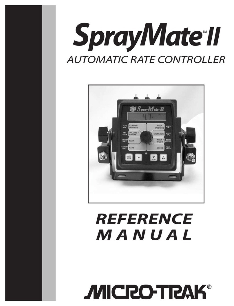
micro-trak SprayMate II User manual

1
Spray
M
ate II
AUTOMATIC
RATE CONTROLLER
REFERENCE
MANUAL
TM
1
1
1
1
1
1
1
1
1
1
1
1
1

2
P.O. Box 99
111 East LeRay Avenue
Eagle Lake, MN 56024-0099
Copyright © 2017
Micro-Trak® Systems, Inc.
Printed in the U.S.A.
SprayMate II is an electronic control system that can help you achieve maximum yields and operate more cost-effectively by
providing the information you need to maintain proper application rates of liquid chemicals and fertilizer. SprayMate II has
been designed for easy installation and operation. However, since each installation will vary depending on your equipment,
please take time to familiarize yourself with this manual and the actual components before beginning. Following the
procedures described in this manual will ensure proper performance and help avoid problems or questions once you are in
the field.
This manual is written for the SprayMate II, which may be used for either English or Metric measurement. Please read the
manual carefully and follow the instructions as they apply to your usage.
If you do encounter a problem that cannot be corrected by reviewing this manual, consult your dealer or distributor, or contact
a Micro-Trak® technician for assistance.
Toll Free in U.S. or Canada: (800) 328-9613 or (507) 257-3600
Fax: 507-257-3001
AUTOMATIC RATE CONTROLLER
REFERENCE MANUAL
Spray
M
ate II
TM

3
Table of Contents
Component Parts and Assembly Hardware .................................................................................................................................................5-6
SprayMateTM II System Overview............................................................................................................................................................................7
SprayMateTM II Wiring Diagram...............................................................................................................................................................................8
Installation........................................................................................................................................................................................................................9
Mounting the Display Console and Switch Kits..............................................................................................................................................9
Electrical Installation .........................................................................................................................................................................................10
Speed Sensor Installation................................................................................................................................................................................11
Magnets........................................................................................................................................................................................................... 11
Connecting the Speed Sensor Cable....................................................................................................................................................12
Speed Sensor Options................................................................................................................................................................................12
SprayMateTM II Plumbing Overview (Bypass) ..........................................................................................................................................13
SprayMateTM II Plumbing Overview (Inline)............................................................................................................................................. 14
Mounting and Plumbing Flowmeter..........................................................................................................................................................15
Installing Flow Sensor Cable....................................................................................................................................................................15
Manual Pressure Relief Valve................................................................................................................................................................... 15
Range Adjust Valve ..................................................................................................................................................................................... 16
Servo, Throttling Valves.............................................................................................................................................................................16
Remote Run/Hold................................................................................................................................................................................................17
Care and Maintenance of your SprayMateTM II.............................................................................................................................................17
SprayMateTM II Console Functions ......................................................................................................................................................................18
Calibration .....................................................................................................................................................................................................................19
English/Metric Selection ..................................................................................................................................................................................19
Entering Calibration Values............................................................................................................................................................................20
Radar or GPS Speed Sensor Calibration ..............................................................................................................................................21
Determining Wheel Circumference...................................................................................................................................................... 21
Drive Shaft Speed Sensor Calibration .................................................................................................................................................. 21
Factory-loaded Calibration Values ........................................................................................................................................................22
Exiting Cal.......................................................................................................................................................................................................22
“Special” Calibration .........................................................................................................................................................................23
Units ..........................................................................................................................................................................................................................24
Valve Voltage .........................................................................................................................................................................................................24
Material ....................................................................................................................................................................................................................24
Valve Response Speed........................................................................................................................................................................................ 24
Fill Tank Size ...........................................................................................................................................................................................................24
Tank Alarm Set Point...........................................................................................................................................................................................24
Auto Shutoff On/Off............................................................................................................................................................................................ 24
Auto Delay Time ...................................................................................................................................................................................................24
Exiting “Special” Cal.............................................................................................................................................................................................24
Operation .............................................................................................................................................................................................25
Console Switches, Buttons and Lights .........................................................................................................................................................25
Rotary Switches & Buttons................................................................................................................................................................................26
Resetting System Counters............................................................................................................................................................................... 27
Clearing System Counters.................................................................................................................................................................................28
Pre-field System Checkout - Bypass Servo...................................................................................................................................29
Pre-field System Checkout - Inline Servo.....................................................................................................................................30
Pre-Field System Checkout - Bypass & Inline Servo ..................................................................................................................30

4
Table of Contents (cont.)
Troubleshooting .........................................................................................................................................................................................................31
Messages/Warnings...................................................................................................................................................................................................31
General ....................................................................................................................................................................................................................32
Console Appears Dead, Speed is Always Zero or Erratic .............................................................................................................. 32
Area Count is Inaccurate, Distance Count is Inaccurate ............................................................................................................... 32
No Readout of Gallons (liters) or Gallons per Minute (liters per minute), Booms Shut-off.............................................. 32
Total Liquid used is Inaccurate...............................................................................................................................................................32
Console is Erratic in Operation ............................................................................................................................................................... 32
Displayed Measurements do not Make Sense, Display Reads “OFL” ......................................................................................32
Checking Individual Components ...............................................................................................................................................................33
Console, Harness, Electrical Interference, Power.............................................................................................................................33
Accessory Power, Run/Hold Hall-effect Sensor ................................................................................................................................ 33
Magnetic Hall-effect Speed and Flow Sensors ................................................................................................................................. 33
Checking Console Inputs.................................................................................................................................................................................34
Plumbing ................................................................................................................................................................................................................34
Plumbing Troubleshooting Charts........................................................................................................................................................35
Plumbing Guidelines.................................................................................................................................................................................................35
General ....................................................................................................................................................................................................................35
Pump inlet......................................................................................................................................................................................................35
Agitation .........................................................................................................................................................................................................35
Servo................................................................................................................................................................................................................. 35
Flowmeter ......................................................................................................................................................................................................35
Pump ................................................................................................................................................................................................................36
Valve Purpose and Adjustments..................................................................................................................................................................36
Tank Shut-off Valve.....................................................................................................................................................................................36
Agitation Shut-off Valve............................................................................................................................................................................36
Pressure Relief Valve................................................................................................................................................................................... 36
Range Adjust Valve ............................................................................................................................................................................................ 36
Throttle Valve................................................................................................................................................................................................36
Appendices ....................................................................................................................................................................................................................37
Appendix A: Optional Speed Sensor Mounting Installation............................................................................................................38
Mounting on Drive Shaft ..........................................................................................................................................................................39
Appendix B: Fine Tuning Speed/distance Calibration Valve........................................................................................................... 40
Fine Tuning Speed/Distance Calibration Value with Run/Hold Kit........................................................................................... 40
Fine Tuning Speed/Distance Calibration Value without Run/Hold Kit....................................................................................41
Appendix C: Fine Tuning Flowmeter Calibration Value.....................................................................................................................42
Appendix D: Flowmeter Assembly.............................................................................................................................................................. 43
Appendix E: Radar Adapter Cables ............................................................................................................................................................. 44
Appendix F: SprayMateTM II NH3 Specific .................................................................................................................................................45
Wiring Diagram ............................................................................................................................................................................................45
Components Parts and Hardware .........................................................................................................................................................46
Single-Section System Diagram............................................................................................................................................................. 47
Speed Sensor Installation .........................................................................................................................................................................48
NH3 Kit Plumbing Installation................................................................................................................................................................. 49
NH3 Kit Vapor Tube Installation.............................................................................................................................................................50
Console Functions.......................................................................................................................................................................................51
Calibration Factors ......................................................................................................................................................................................52
Fine Tuning Flow Cal.................................................................................................................................................................................. 53
Field Operation............................................................................................................................................................................................. 54
Flowmeter Assemblies...............................................................................................................................................................................55
Appendix G: EMD for SprayMateTM II: .........................................................................................................................................................57
Appendix H: Conversion Chart......................................................................................................................................................................59
Appendix I: Replacement Parts List ............................................................................................................................................................ 60
Micro-Trak® Warranty............................................................................................................................................................................................... 61
5
Component Parts and Assembly Hardware
Owner’s Manual
P/N 14943
Console Mount Kit
P/N 13181
SprayMateTM II Console
P/N 14869
5’ Hall-effect Flow Sensor Cable
with threaded sensor.
P/N 13096
FM750 GFN Flowmeter
P/N 11501 M-T 1” Electric
Servo Valve
P/N 14928
Spray
M
ate II
AUTOMATIC
RATE CONTROLLER
REFERENCE
MANUAL
TM
C
E
(2)
(2)
(2)
(2)
(2)
(2)
(2)
C. 15’ 3-Pin Extension
Cable M/P 150
P/N 13207
B. 14” Nylon cable ties (10)
P/N 12910
F. Hardware Bag
P/N 13251
D. Speed sensor mounting bracket
P/N 10013
E. Magnets (6)
(2 in hardware bag)
P/N 12069
G. Magnet Clip (6)
P/N 10080
Speed Sensor Kit P/N 01531 (1)
Including items A-G, below:
A. 5’ Hall-effect Flow Sensor Cable
with threaded sensor.
P/N 13096

6
14” Nylon cable ties (10)
P/N 12910
120” 10-pin
extension cable
P/N 14316
72” ignition cable
P/N 14314
Run/Hold Switch
P/N 21963
Power Switch
P/N 21779
Component Parts and Assembly Hardware (cont.)
Before beginning installation, check the carton contents for the following items:
Boom/Servo/Flow Harness
P/N 14313
Power Cable
P/N 14315

7
SprayMateTM II System Overview
P/N 21778
P/N 21963

8
P/N 21963
P/N 21779
P/N 14313
P/N 14316
SprayMateTM II Wiring Diagram

9
Installation
Mounting the Display Console
Illustration 1A
Illustration 1B
Mount Knob
Carriage Bolts
Rubber Washer
Rubber Washer
Mount Knob
Switch Bracket
Switch Bracket
Select a mounting location which seems most workable,
and best fits your needs. It should be convenient to reach
and highly visible to the operator. DO NOT INSTALL IN A
POSITION THAT OBSTRUCTS THE VIEW OF THE ROAD
OR WORK AREA. Whenever possible, avoid locations that
expose the console to direct sunlight, high temperature,
strong chemicals or rain.
Place the mounting bracket in the selected location, mark
holes, drill ¼” (7mm) holes and mount bracket with bolts,
lock washers and nuts provided. (Use self-tapping screws if
not practical to use bolts.) See Illustration 1A.
Put rubber washers on carriage bolts and put the bolts
through the bracket holes from the inside out. Place console
over carriage bolt heads.
Install the switches over the carriage bolts and alongside the
console brackets. Install the mount knobs on the carriage
bolts and tighten to secure the console and switches in
place. See Illustration 1B.
Drill ¼” (7mm)
holes for bolts,
or 3/16“ (5mm)
holes for self-
tapping screws.
Bolts
Lockwashers
and nuts

10
Connecting to ignition to turn SprayMateTM II system on/off.
Illustration 2
Illustration 3
Installation (cont.)
Electrical Installation
This section explains how to hook-up your SprayMateTM II to
a 12-volt power connection, and how to connect your boom
shut-off valves.
The SprayMateTM II must be connected to a 12-volt DC
negative ground electrical system. Use your test light to
locate a terminal or wire connected to your ignition switch
which is “hot” when the ignition is turned on and “dead”
when the ignition is off.
POWER/BATTERY CONNECTION
Locate the power cable lead on the SprayMateTM II harness
and route to the battery. In routing cable to console, avoid
areas where the cable may be subjected to abrasion or exces-
sive heat. Attach the BLUE wire (ground) to a screw or bolt
on the equipment frame. See Illustration 2. Be sure there is a
good metal-to-metal contact. Connect the ORANGE wire to
the positive battery terminal.
Connect the power to the SprayMateTM II console by plugging
the 2-pin M/P tower on the power cable into the 2-pin M/P
shroud of the display console.
ON/OFF SWITCH CONNECTION
The SprayMateTM II system harness includes a provision for
either using a switched (ignition) source or the optional
power switch to turn the system on.
If the switch is used, simply mount the switch bracket as
shown on page 11, and plug the connector into the mating
cable from the console. If you want to use the ignition
switch to turn the system on and off, using the 72” 2-wire
extension cable, plug the connector into the mating plug
for the console and connect the black wire to the switched
power source (terminal or wire). DO NOT connect the red
wire.
Your SprayMateTM II is equipped with an electronic memory
which does not require a constant supply of power to retain
daily totals or calibration values. This type of memory
conserves battery power and will not discharge the vehicle’s
battery when equipment is not in use.
Hot
(Orange)
10-Amp In-line
Fuse Required
Ground
(Blue)
+12 VDC
(Red)
Carefully route power
cable to a 12VDC source
Attach BLACK wire to
terminal or lead that is “hot
”
with ignition on.
4-amp in-line fuse (Not Provided) required for unprotected circuits
DO NOT connect
the RED wire.
Tie back and tape o.

11
Magnets
Please read the following information about magnet spacing
and polarity.
The number of magnets that must be used depends on
the size of your tire and where you mount the sensor. On
tractor or implement wheels the general rule of thumb is one
magnet for each wheel bolt (minimum of two, and always an
even number). For drive shafts or small wheels (ATV’s), two
magnets are usually adequate.
Some installations may require that more than two magnets
be installed. To determine the number of magnets required,
measure the distance traveled of one revolution of the sensor
equipped wheel in inches (meters). Divide that measurement
by 20 for English and Turf units, or by .5 for Metric units, and
then round up to the nearest even number (always use an
even number of magnets). That number will be the minimum
number of magnets required for the installation.
Example in English/Turf units: If your revolution measurement
is 97 inches, dividing that number by 20 gives you a value of
4.85. Rounding 4.85 up to the nearest even number is 6. For
this example, the minimum number of magnets required is 6.
Example in Metric units: If your revolution measurement is
2.5 meters, dividing that number by .5 gives you a value of
5. Rounding 5 up to the nearest even number is 6. For this
example, the minimum number of magnets required is 6.
The magnets provided by Micro-Trak® are marked with a
punched dashed line on the SOUTH pole side of the magnet.
See Illustration 5A.
Always use an even number of magnets, and always alternate
the polarities of the magnets as you go around the wheel
hub or drive shaft.
To install, mount the first magnet with the SOUTH pole side
(dashed line) facing toward the hub or shaft. Mount the
second magnet with the NORTH pole side facing toward the
hub or shaft. See Illustration 5B.
For proper operation, the magnets must be evenly spaced
around the wheel or drive shaft. The magnets must be at
least 1” apart. See Illustration 5C.
PLEASE NOTE: If you have purchased a Vansco speed
sensor, disregard the following section on magnetic
speed sensors and install the Vansco as described in the
instructions included with the unit.
Locations where the sensor may be installed:
1. Non-driven wheel on tractor, vehicle or implement. This
is less susceptible to errors resulting from wheel slip.
2. Tractor, vehicle or planter drive shaft. This type of
mounting is recommended for trucks, four-wheel drive
tractors or other equipment that has poor or no access
to a non-driven wheel.
Installation (cont.)
Speed Sensor Installation
Locate the Following Parts
• Speed Sensor Cable (Green Body)
• Mounting “L” Bracket
• Magnet Clips
• Magnets
• Cable Ties
Illustration 5A
Illustration 5B
S
N
North
North
North
South
South
South
1
2
43
5
6
Test magnet
should alternately
attract and repel.
Refer to the diagram on the following page for general
mounting instructions. For specific mounting instructions,
refer to Appendix A in the back of this manual.
NOTE: Magnets may be attached mechanically as shown or
adhered with epoxy or other high quality adhesive. When
using adhesive, thoroughly clean the area of dirt and oil.
Illustration 5C
1” Minimum
Drill lug
bolt hole
and bend
to t hub
Magnet

12
Attaching Magnets
The magnets are attached to a wheel hub or drive shaft and
the speed sensor is mounted directly over the magnet. When
the wheel or drive shaft begins turning, a speed impulse
is sent to the SprayMateTM II console every time a magnet
passes by the tip of the speed sensor. For the speed sensor
to operate properly, the spacing between the magnets and
the tip of the sensor must always remain constant. Before
permanently mounting any parts, be sure that the location
you have selected will meet the following requirements.
See Illustration 6.
NOTE: Observe magnet polarities (see previous page).
Installation (cont.)
Speed Sensor Installation Illustration 6
45° max
Sensor
(Green body)
Magnet
3/8” nuts
Bracket must
be rigidly
mounted
Sensor assembly must not
be mounted more than
45° from perpendicular
¼” to ½” air gap
The optional Run/hold sensor, also uses the same type of
connector as the speed and flow sensors. However, the Run/
hold sensor has a GRAY tie near the 3-pin connector, the
sensor body is BLACK, and it always connects to the main
harness lead with the GRAY tie. See SprayMateTM II Wiring
Diagram on page 10.
Connecting the Speed Sensor Cable
The speed sensor cable has a GREEN sensor body and mates
with the main harness cable having a YELLOW cable tie near
the 3-pin M/P connector. Make certain that you install the
correct sensor cable and connect it to the correct connector
on the main harness. The speed sensor and the flow sensor
are identical, but must be connected to the proper harness
connector. The speed sensor always connects to the main
harness lead with the YELLOW tie and flow sensor always
connects to the main harness lead with the GREEN tie. See
SprayMateTM II Wiring Diagram on page 10.
SENSOR IDENTIFICATION CHART
SENSOR SENSOR BODY COLOR MAIN HARNESS TIE COLOR
Speed Green Yellow
Flow Green Green
Run/Hold Black Gray
Contact a Micro-Trak® sales representative for details on any of these products,
or call Micro-Trak® Systems, Inc. at 1-800-328-9613.
Speed Sensor Options
NOTE: In addition to the standard Hall-effect magnetic
speed sensor, the SprayMateTM II may be interfaced with a
variety of other speed sensing equipment. Several options
are listed below.
ASTRO SERIES OR OTHER GPS SPEED SENSOR INTERFACES
The SprayMateTM II may also be used with most GPS speed
sensors that output a pulsed signal, such as the Micro-Trak®
Astro II and 5, SkyTrak or Dickey-John GPS speed sensors. An
adapter cable may be required.
VANSCOTM RADAR SPEED SENSOR
The Vansco radar speed sensor uses a microwave (radar)
signal to deliver a reliable, accurate speed signal for electronic
equipment. It features state-of-the-art electronic design/
manufacturing, rugged aluminum housing and complete
testing and certification.
RADAR INTERFACE
The SprayMateTM II may also be interfaced with most popular
radar ground speed sensors. An adapter cable is required for
proper interface.
SEE APPENDIX I FOR LIST OF ADAPTER CABLES FOR RADAR.
Astro 5 GPS Speed Sensor
Vansco Radar Speed Sensor

13
Installation (cont.)
SprayMateTM II Plumbing Overview
Bypass Configuration
Control valve flow bypasses flowmeter
Fluid bypass path

14
Installation (cont.)
SprayMateTM II Plumbing Overview
In-Line Configuration
Control valve flow is inline with flowmeter
Control valve flow is inline with flowmeter.

15
Installing Flow Sensor Cable
With the flowmeter in place, install the flow sensor cable.
The flow sensor cable has a GREEN sensor body and mates
with the 3-pin connector on the main harness marked with
a GREEN cable tie. Screw sensor all the way into hole of
flowmeter. Tighten 3/8” jam nut to secure sensor in place.
Uncoil flow sensor cable and carefully route it to meet the
main harness flow connector marked with GREEN tie. Align
connectors and press firmly together until locking tab clicks
into place. Secure cable with ties provided. See Illustration 8
and SprayMate IITM II Wiring Diagram on page 10.
NOTE: Sensors with GREEN bodies can be used for either
SPEED or FLOW but not for RUN/HOLD.
FLOW SENSOR
CABLE CONNECTOR
MAIN HARNESS
FLOW CONNECTOR
GREEN TIE
WEATHER -PACK
Connect flow sensor cable to green-tie console cable.
Illustration 8
Manual Pressure Relief Valve
If you have a positive displacement pump or a centrifu-
gal pump capable of generating excessive pressure, you
must install a pressure relief valve and adjust it to a safe
maximum pressure. If a positive displacement pump is
operated without a pressure relief valve, damage may result
to pump or other plumbing component. See Illustration 9.
Illustration 9
Tee “C”
For positive displacement pumps
Pressure Relief Valve
Installation (cont.)
Mounting and Plumbing Flowmeter
Sprayer Line*
Locknut
Sensor
(green body)
Flowmeter
* NOT SUPPLIED
“L” Bracket*
Hose Clamps*
¾” NPT Male Fitting*
Hose Clamps*
Hose Clamps*
Illustration 7
The flowmeter must be installed in the main line after any strainers,
return lines, or valves. Securely mount flowmeter in an area away
from intense vibration. A vertical installation with flow entering the
bottom is preferred, especially at rates below 5 gallons per minute.
Other orientations are sufficient providing the flowmeter remains
full of fluid. To avoid erratic flow readings allow a minimum of 6”
of straight tubing at the flowmeter input and output. If installation
constraints don’t allow this keep bends as gentle as possible.
Micro-Trak® flow meters are bidirectional (exception: green plastic
turbine and mag flowmeters are one direction only). Flipping the
flowmeter periodically (black nylon and stainless steel Micro-Trak®
manufactured models) to reverse the flow will greatly extend the life
of the flowmeter by evening out bearing wear.

16
Servo, Throttling Valves
For BYPASS installations, the servo valve installs in an
unrestricted return line to the inlet of the pump or directly
into the tank. The console must be calibrated for bypass
operation, see Calibration section. DO NOT install the servo
valve closer than 12” to the flowmeter. The servo valve has
a flow direction decal on it. Make certain that the actual flow
direction matches the decal on the servo valve. DO NOT
install the servo valve in the agitation line. Slow response
time and marginal operation may result. The return line
should tee from the main line just after the throttling valve.
See Illustration 11. The throttling valve is used to limit the
output (set maximum output) of the pump to the flowmeter
and servo valve. The throttling valve is adjusted to put the
servo valve in its optimal operating range. Please refer to
Pre-Field System Checkout on page 32-33 for proper valve
adjustment procedure.
The servo valve connects directly to the 3-pin connector on
the main harness. If more length is required, use a 3-pin W/P
extension cable of the appropriate length.
IMPORTANT NOTE: If using the SprayMateTM II with an
old-style Micro-Trak® servo valve, the valve voltage must
be set to 8 volts. See “Special” Calibration Valve Voltage
section on page 27.
NOTE: The servo valve may be installed in the main spray
line as shown in Illustration 12. For In-line installations,
you will need to calibrate the system for INLINE operation,
see page 25.
Illustration 11
Servo Valve
Cable
From Pump
Throttling
Valve
To Flowmeter
Servo Valve
Return to pump
inlet or unrestricted
return to tank.
ByPass
Servo
Flowmeter
From Pump
Illustration 12
InLine
Installation (cont.)
Mounting and Plumbing Flowmeter
Range Adjust Valve
With oversized pumps, it may be necessary to install a range
adjust valve. The range adjust valve will reduce the pump’s
output to the rest of the system. Adjustment of this valve
is covered in the Pre-Field System Checkout, pages 32-33.
See Illustration 10.
Tee “C”
Range
Adjust Valve
Tee “A”
For oversized pumps Illustration 10

17
Remote Run sensor on hydraulic cylinder. Magnet and
sensor are in line when equipment is lowered and operating.
Care and Maintenance of your SprayMateTM II
Console
Store the console in a cool dry location if it will not be used for an extended period of time, such as during the
off-season. As with any electronic equipment, use care in cleaning so that water or other liquids do not enter
the case. Thoroughly flush Flowmeter with clean water, install plastic shipping plugs and keep from freezing.
Precautions
• The input pressure on the glass-filled nylon flowmeter FM750 GFN should not exceed 100 PSI (689 kpa).
• Do not expose the flowmeter to liquid temperatures exceeding 130 degrees F (55 degrees C).
• Some chemicals may damage the turbine material. If you are in doubt, contact the chemical manufacturer.
Installation (cont.)
Remote Run/Hold
Lift Wheel Mounting
Sensor (Black body)
1/8” to 3/8”
(6 mm to 13 mm)
when wheels are up
Magnet
South
North
Hydraulic Cylinder Mounting
Run
Position Hold
Position
Sensor
(Black body)
Magnet
North
South
The run/hold sensor cable has a BLACK body and mates
with the main harness cable having a GRAY cable tie near
the 3-pin M/P connector. Make certain that you install the
correct sensor cable and connect it to the correct connector
on the main harness. See Illustrations to the right.
IMPORTANT:
If not using Run/Hold cable for remote use, make certain a
dust cover with jumper is installed.
• The basic idea is to attach a magnet to a lever or some
part of the equipment that moves when the implement
is raised and lowered. The Hall-effect Run/Hold sensor is
sensitive only to the south pole of the magnet. Install
the magnet with the dashed line facing the sensor.
When the magnet is away from the sensor, the console
will be in HOLD and the area and distance counting
functions will be disabled. NOTE: The Run/Hold Kit
includes a 5’ sensor cable and 10’ extension. You may
require additional extension cables which are available
in 5 ft. (1.5 m), 10 ft. (3 m), 15 ft. (4.5 m), 20 ft. (6 m) and
25 ft. (7.6 m) lengths.
• You may also use a toggle or other type switch. Simply
cut the black jumper wire in the dust cover and splice on
an appropriate length of wire to reach your switch. Do
not connect to a switch with power.
When switch is closed, console is in RUN. When the switch is
open, the console is in HOLD.

18
SprayMateTM II Console Functions
The SprayMate IITM II features a large, easy-to-read liquid crystal display, easy-to-use rotary dial and lighted
panel for night use.
TANK: Displays gallons (liters)
of liquid remaining or lbs. (kg)
of NH3 remaining.
INLINE/BYPASS: For establishing servo polarity. (If servo is
in the main spray line, select “Inline”. If servo is installed in a
return line, select “Bypass”.)
ADJUST RATE: Used in calibration mode to enter an
amount of change for on-the-go adjustments to the
target rate (GPA/LPH), or lbs/acre (kg/hectare) N.
TARGET RATE: Used in calibration mode to enter the target
application rate (GPA/LPH) or lbs/acre (kg/hectare) N.
RATE: Displays application rate
GPA(LPH), or lbs. N/acre (kg of N/
hectare).
AREA 1 2 3: Keeps a running count of the total acres
(hectares) worked. May be reset. (Note: VOLUME and AREA
counters work in pairs, if AREA counter 1 is reset, it also resets
VOLUME counter 1.
AREA/HOUR: Displays current
work rate in acres per hour
(hectares per hour).
WIDTH CAL: Used in calibration mode to enter the working
width of your sprayer booms or other equipment.
SPEED: Displays ground speed
in miles per hour (kilometers per
hour).
SPEED CAL: Used in calibration mode to enter the speed
calibration number in inches (cm) per pulse.
TEST SPEED: Used in calibration mode to enter a test speed
in miles per hour (kilometers per hour).
MIN FLOW: Used in the calibration mode to enter the
minimum flow rate (GPM/LPM) of the spray boom.
VOLUME 1 2 3: Displays total gallons (liters) or lbs. (kg)
of NH3 applied. May be reset. (Note: VOLUME and AREA
counters work in pairs, if VOLUME counter 1 is reset, it also
resets AREA counter 1.
FLOW CAL: Used in calibration mode to enter the calibration
value assigned to your flowmeter (see flowmeter tag.)
WARNING LIGHT: Indicates over
or under application of 10% of the
Target Rate. Also lit when in CAL.
Calibration Positions Calibration Positions
VOLUME/MINUTE: Displays total
gallons (liters) of liquid applied per
minute, or lbs. (kg) NH3 per minute.
DISTANCE: Displays distance traveled
in feet (meters). May be reset.
Soft Key Functions
Key which changes operation
from automatic control to
manual.
AUTO
MAN
This key is used to enter & exit
the calibration mode.
CAL
PROGRAM KEYS: Used to increment and
decrement the different calibration values.
RESET
• RESET when not in CAL, clears
the selected counter when held
for two seconds.
• When in CAL, the “+” key
increases and the “-” decreases
the value displayed.

19
Illustration 14
The SprayMateTM II is capable of displaying information in
American English or standard Metric measurement. The
SprayMateTM II is shipped from the factory programmed
for English. Note that the following procedures will also
load factory default calibration values. To simply change
units without loading defaults, see the “Special” Calibration
section.
METRIC
• You must be in HOLD or have all booms OFF to enter
Cal. To activate the Metric mode, turn power OFF and
place the rotary switch at “AREA.” Hold down both the
“CAL” and “-” keys and turn power ON. See Illustration 13.
The console will display LOAd for two seconds. Once
LOAd is displayed, release the two keys. To “lock-in”
Metric mode you must enter and exit calibration. Press
and hold the CAL key until “CAL” icon appears on the
display. The console is now in calibration and Metric
mode is selected. Exit CAL by pressing and holding
the “CAL” key until CAL disappears from the display
(approximately 1 second). NOTE: you must exit CAL to
lock in Metric units.
ENGLISH
• You must be in HOLD or have all booms OFF to enter
Cal. To activate the English mode, turn power OFF and
place the rotary switch in the VOLUME position. Hold
down both the “CAL” and “-” keys and turn power ON.
The console will display LOAd. Once LOAd is displayed,
release the two keys. To “lock-in” English mode you
must enter and exit calibration. Press and hold the CAL
key until “CAL” lights on the display. The console is now
in calibration and English mode is selected. Exit CAL by
pressing and holding the “CAL” key until CAL disappears
from the display (approximately 1 second). NOTE: you
must exit CAL to lock in English units.
NOTE: In metric, the width will have a decimal point, in
English there is no decimal point. Also, changing from English
to Metric mode may change or alter any previously entered
calibration values. After switching measurement modes, con-
firm that all calibration values are correct.
IN ALL CALIBRATION OPERATIONS:
1. Turn all boom switches OFF or put system in “HOLD”.
2. Press and hold the “CAL” key for 1 second to select the
calibration mode. The console display will display the
“CAL” icon, the currently selected calibration value, and
the red warning light will turn on.
3. Turn the rotary dial to the desired “CAL” position. Then
use the “+” or “-” key to adjust the displayed value
up or down as needed. Adjust ALL necessary values.
See Illustration 14.
4. Hold the “CAL” key again for 1 second to exit calibration.
“CAL” will disappear from the display.
NOTE: You must exit CAL to save changes.
WIDTH
CAL
FLOW
CAL
MIN
FLOW
ADJUST
RATE
TARGET
RATE
SPEED
CAL
INLINE
BYPASS
TEST
SPEED
VOLUME /
MINUTE DISTANCE
AREA /
HOUR
VOLUME
(1) (2) (3)
RATE SPEED
AREA
(1) (2) (3)
CAL
AUTO
MAN RESET
CAL HOLD
SprayMate™
II
TANK
Press to enter or exit
calibration mode.
Press to increase or
decrease values.
Red warning light will
be lit when in CAL.
WIDTH
CAL
FLOW
CAL
MIN
FLOW
ADJUST
RATE
TARGET
RATE
SPEED
CAL
INLINE
BYPASS
TEST
SPEED
VOLUME /
MINUTE DISTANCE
AREA /
HOUR
VOLUME
(1) (2) (3)
RATE SPEED
AREA
(1) (2) (3)
CAL
AUTO
MAN RESET
MANAUTO
CALHOLD
1 2 3 4 5
SprayMate™II
TANK
Illustration 13
Calibration
English or Metric?

20
To enter or change any of the system’s calibration values,
you must enter calibration mode. To enter calibration mode,
STOP the vehicle, turn all booms OFF or put the console in
HOLD and press and hold the CAL button until the “CAL” icon
appears (approximately one second). (NOTE: Calibration
may be entered while moving, but it is not recommended to
attempt calibration while the vehicle is moving.) The console
will remain in calibration mode, with the RED warning light
illuminated until you exit calibration or turn power OFF.
Once in calibration mode, you may change any one, all, or
none of the values, in any order.*To select a calibration
position, simply turn the rotary selector to the desired
position. Calibration positions are identified by the WHITE
labeling on each side of the rotary selector. All values are
entered and adjusted using the “+” and “-” buttons on the
front panel.
* TEST SPEED MUST BE LAST.
Calibration (cont.)
Entering Calibration Values
TARGET RATE: Enter the value for the
desired target application rate in gallons per
acre (liters per hectare) or lbs. of N per acre
(kgs of N per hectare). This is the application
rate that the console
will lock onto when
operating in AUTO. TARGET
RATE RATE
ADJUST RATE: Enter the value for the desired amount
of change in gallons per acre (liters per hectare) to be
used for making on-the-go rate adjustments
when operating in AUTO. For example, if a
value “1.0” is entered,
you will be able to
increase or decrease
your application rate
in one-gallon (liter) or lb. (kg) increments during operation in
AUTO. To disable this feature, simply enter “.0” for a value.
ADJUST
RATE TANK Your “working” width per boom section will be the number
of nozzles on the boom section times the nozzle spacing in
inches (mm). For example, if you have 8 nozzles spaced at 12
inches, the working width of the boom section is 96 inches.
See Illustration below.
CAUTION: If spray-lines are pressurized, nozzles may spray
during this step.
WIDTH: Enter the effective working width, in inches (meters)
for the boom section
currently shown on the
display. It is simplest to
start with all booms ON
and then turn each boom OFF, from left to
right, after calibrating the width. Note that
the system must be in RUN (not HOLD) to
display boom numbers. Repeat this procedure
for each boom section. Enter a value of “0”
(.000) for any unused boom sections.
WIDTH
CAL
AREA
(1) (2) (3)
MIN FLOW: The purpose of this calibration value is to
prevent the system from applying below the recommended
minimum rate for the nozzles. The minimum flow rate
in gallons per minute
(liters per minute)
based on the nozzles
being used, for the
entire boom on the sprayer. DO NOT enter
the actual flow of your spray application. For
example: If the minimum flow rate for the nozzle you are
using is .22 GPM at their minimum recommended pressure
and your boom has 20 nozzles, enter 4.4 as the MIN FLOW
value (.22 x 20 = 4.4). The system WILL NOT apply at a rate
lower than this value when spraying in AUTO. This value
should be checked/ changed for each different nozzle that
you use.
APPLICATION NOTE: Over-application may occur with
MIN FLOW set if ground speed is too slow.
MIN
FLOW
VOLUME /
MINUTE
Illustration 17
FLOW CAL: This position is used to calibrate the flow-
meter for accurate liquid measurement. Every flowmeter
is calibrated with
water at the factory
and assigned a “FLOW
CAL” value to make it
operate properly with
the SprayMateTM II console. This number
is stamped on the metal tag attached to
the flowmeter. See Illustration 17. This is
a starting point only. If your spray solution
has a specific gravity or viscosity that is different than
water, flowmeter calibration should be done for the specific
solution (Please refer to Fine-Tuning Flowmeter Calibration
in Appendix C on page 45.)
FLOW
CAL
VOLUME
(1) (2) (3)
Other manuals for SprayMate II
1
This manual suits for next models
1
Table of contents
Other micro-trak Controllers manuals

micro-trak
micro-trak MT-9000 FTW User manual

micro-trak
micro-trak MT-400 LDI User manual

micro-trak
micro-trak MT-2405FTW II User manual

micro-trak
micro-trak MT-2405 FTW User manual

micro-trak
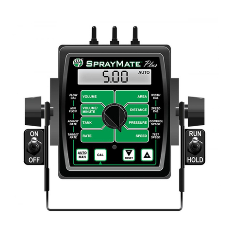
micro-trak SprayMate Plus User guide

micro-trak
micro-trak MT-9000 Series User manual

micro-trak
micro-trak DUAL CONTROL MT-3405D User manual

micro-trak
micro-trak DrillMaster User guide

micro-trak
micro-trak AgriCruise II User manual

micro-trak
micro-trak MT-3405F II User manual