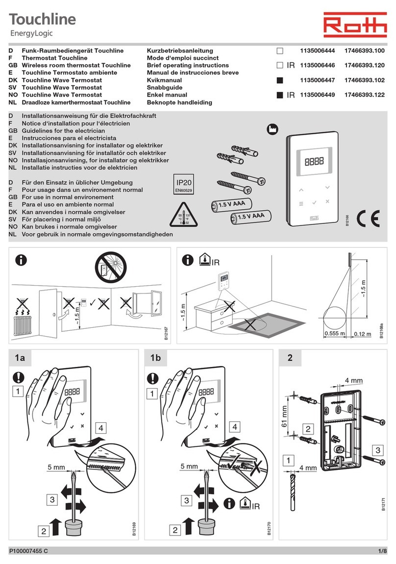
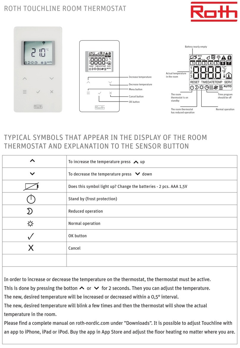
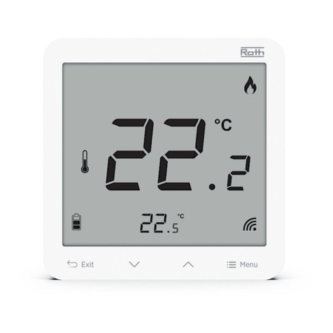
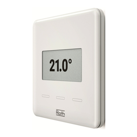
Roth EnergyLogic Touchline/wireless User manual

Living full of energy
Control system EnergyLogic
Wireless control Touchline
User manual
Energy systems

User Manual Roth EnergyLogic Touchline/Wireless
Table of Content
P100011294 E 3
Table of Content
1General ...................................................................................................9
1.1Information regarding this user manual ........................................9
1.2Explanation of symbols...............................................................10
1.3Limitation of liability.....................................................................11
1.3.1Information in case of failure of the radio system...........11
1.4Copyrights...................................................................................12
1.5Scope of supply...........................................................................12
1.6Customer service ........................................................................12
1.7Area of application radio system.................................................13
2Safety....................................................................................................14
2.1Intended use................................................................................14
2.2Changes and modifications.........................................................14
2.3Requirements for professionals ..................................................15
2.4Safety and health hazards ..........................................................15
2.4.1Warning sign...................................................................15
2.4.2Risk and safety ...............................................................15
3Identification........................................................................................16
3.1Name plate..................................................................................16
3.2Types (part numbers of product range) ......................................16
3.2.1Wireless connection module...........................................16
3.2.2Wireless room thermostat...............................................17
3.2.3Accessories.....................................................................17
4Design and function............................................................................18
4.1Design.........................................................................................18
4.1.1Wireless connection module with LAN ...........................18
4.1.1Wireless connection module without LAN ......................19
4.1.2Wireless room thermostat...............................................20
4.2Function.......................................................................................20
4.3Operating and monitoring elements............................................23
4.3.1Wireless connection module...........................................23
4.3.2Wireless room thermostat with display...........................26
4.3.1Wireless room thermostat without display......................29

User Manual Roth EnergyLogic Touchline/Wireless
Table of Content
4 P100011294 E
5Installation........................................................................................... 30
5.1Wireless connection module ...................................................... 30
5.2Wireless room thermostat........................................................... 31
5.2.1Place of installation and general installation notes........ 31
5.2.2Wireless room thermostat with display ..........................32
5.2.3Wireless room thermostat without display .....................34
5.2.4Wireless room thermostat with 230 V connection.......... 36
6Electrical connections........................................................................ 38
6.1Safety.......................................................................................... 38
6.2General wiring notes................................................................... 38
6.3Wireless connection module ...................................................... 40
6.3.1Connection diagram
for wireless connection module with LAN...................... 40
6.3.1Connection diagram
for wireless connection module without LAN.................41
6.3.2Perform electrical connections....................................... 41
7Commissioning and operation.......................................................... 51
7.1Addressing.................................................................................. 51
7.1.1Address one wireless room thermostat
to one radio channel....................................................... 52
7.1.2Address one wireless room thermostats
to several radio channels............................................... 52
7.1.3Address several wireless room thermostats
to one radio channel (sensor mode) .............................. 53
7.1.4Test addressing.............................................................. 55
7.1.5Delete addressing .......................................................... 55
7.1.6Combine several wireless connection modules
into a system.................................................................. 56
7.1.7Internal system grid repeater ......................................... 57
7.2Zones.......................................................................................... 59
7.2.1Zone building, assign radio channels to one zone.........59
7.2.2Delete assignment of a radio channel or several radio
channels to a zone......................................................... 60
7.3Change setpoints........................................................................ 61
7.3.1Set room temperature.................................................... 61
7.3.2Set floor temperature ..................................................... 61
7.4Select mode of operation ........................................................... 62
7.5Set time and date ....................................................................... 64

User Manual Roth EnergyLogic Touchline/Wireless
Table of Content
P100011294 E 5
7.6Time programs............................................................................65
7.6.1Overview of the three time programs..............................65
7.6.2Factory settings time program ........................................65
7.6.3Select time program........................................................66
7.6.4Change time program.....................................................67
7.6.5Reset time programs to factory settings.........................70
7.7"eco"-Indicator.............................................................................71
7.8Parameterising function button ...................................................71
7.9Lock / unlock operation of wireless room thermostat..................72
7.10Software update with micro SD-card...........................................73
8Reset values to factory setting (reset)..............................................74
8.1Reset radio system to factory settings........................................74
8.2Reset wireless connection module to factory setting..................74
9Parameter descriptions ......................................................................75
9.1Parameter overview....................................................................75
9.2User menu...................................................................................77
9.3Service menu ..............................................................................81
9.3.1Enter service menu.........................................................81
9.3.2Select parameter group ..................................................81
9.3.3P-20 "General parameters".............................................82
9.3.4P-30 "Parameters for all wireless room thermostats".....84
9.3.5P-40 "Parameters for individual wireless room
thermostats"....................................................................87
9.3.6P-50 "Plant- and topology related parameter"................92
9.3.7P-60 "Control parameters"..............................................94
10Cleaning and maintenance.................................................................99
11Troubleshooting................................................................................100
11.1Wireless connection module.....................................................100
11.2Wireless room thermostat with display .....................................101
11.2.1Procedure for Err1 or Err2..................................102
11.2.2Procedure when "radio signal lost"...............................102
11.2.3Replace batteries of wireless room thermostat ............102
11.3Wireless room thermostat without display ................................103
11.4FAQs.........................................................................................103
11.5Tips and tricks...........................................................................104
12Waste disposal ..................................................................................104

User Manual Roth EnergyLogic Touchline/Wireless
Table of Content
6 P100011294 E
13Accessories....................................................................................... 105
13.1External antenna ...................................................................... 105
13.2External Repeater..................................................................... 106
13.2.1Install the external repeater.......................................... 107
13.2.2Assign the external repeater
to a wireless room thermostat...................................... 108
13.2.3Test the external repeater's radio connection.............. 109
13.2.4Delete the external repeater's radio connection ..........109
13.2.5Assign the external repeater
to a wireless connection module.................................. 110
13.2.6Test addressing of the wireless connection modules
"Slave" and "Master".................................................... 110
13.2.7Check external repeater assignment........................... 111
13.2.8No radio connection with the external repeater –
procedure..................................................................... 111
13.2.9Deactivate LEDs at the external repeater.................... 112
14Technical data................................................................................... 113
14.1Radio system............................................................................ 113
14.2Wireless connection module .................................................... 113
14.2.1Construction and dimensions....................................... 113
14.2.2Electrical connections .................................................. 114
14.2.3Inputs............................................................................ 114
14.2.4Outputs......................................................................... 115
14.2.5Radio power data......................................................... 115
14.2.6Environmental conditions............................................. 115
14.3Wireless room thermostat with display..................................... 116
14.3.1Construction and dimensions....................................... 116
14.3.2Power supply – Battery ................................................ 116
14.3.3Power supply – 230 V AC............................................ 116
14.3.4Performance data......................................................... 117
14.3.5Environmental conditions............................................. 117
14.4Wireless room thermostat without display................................ 118
14.4.1Construction and dimensions....................................... 118
14.4.2Power supply – Battery ................................................ 118
14.4.3Performance data......................................................... 118
14.4.4Environmental conditions............................................. 118
15Menu structure.................................................................................. 119
User Manual Roth EnergyLogic Touchline/Wireless
Table of Content
P100011294 E 7
16Plant examples and communication...............................................121
16.1Plant examples with one wireless connection module..............121
16.2Plant examples with up to five wireless connection modules...124
Index...........................................................................................................125
Factory settings parameters....................................................................132
Factory settings time program ................................................................134

User Manual Roth EnergyLogic Touchline/Wireless
General
P100011294 E 9
1 General
1.1 Information regarding this user manual
This user manual provides important instructions with respect to the use of the
Wireless Connection Module and the Wireless Room Thermostat Touchline.
Compliance with all safety and installation instructions is the basis for safe
working.
Read this manual carefully before the start of any work! It is a part of the
product and need to be made accessible to the user at any time.

User Manual Roth EnergyLogic Touchline/Wireless
General
10 P100011294 E
1.2 Explanation of symbols
Warnings In this user manual warnings are indicated by symbols. The notes are prece-
ded by signal words that express the extent of the risks caused expression.
Always comply with the instructions and act prudently to avoid accidents, and
damages to people and property.
DANGER
... points to an immediate hazardous situation, which leads to death or seri-
ous injury if not avoided.
WARNING
… points to a possible dangerous situation that can result in death or seri-
ous injury if not avoided.
CAUTION
... points to a possible dangerous situation that can lead to minor injuries, if
not avoided.
ATTENTION
... points to a possible adverse situation that can lead to property damage,
if not avoided.
Tips and
recommendations
NOTE
... highlights useful tips, information and recommendations for efficient and
trouble-free operation.

User Manual Roth EnergyLogic Touchline/Wireless
General
P100011294 E 11
1.3 Limitation of liability
All information and instructions in this manual are in accordance with applica-
ble standards and regulations, the state of art technology as well as our many
years of knowledge and experience.
The manufacturer assumes no liability for damages due to:
●Failure to follow the user manual
●Improper use
●Use of untrained personnel
●Unauthorized modifications
●Technical changes.
In addition the following applies: the duties as agreed in the contract, the
"General Terms and Conditions" and the "Terms of Supply" of the manufac-
turer and at the time of the contract applicable statutory regulations.
1.3.1 Information in case of failure of the radio system
The radio system is not failsafe.
The radio system is equipped with an emergency function in which the system
continues to function in a reduced mode. In this emergency mode, the LED of
the channel blinks and the display of the wireless room thermostat shows a
warning symbol.
For the correct operation of the emergency mode following conditions must be
met:
●The wireless connection module must be powered.
●The wireless connection module cannot by external influences such as
lightning to be destroyed.
●Thermal actuators must be connected and functional.
ATTENTION
Possible damage to property due to failure of the system!
The radio system is not failsafe. Note the points above to ensure that the
system is operating properly.

User Manual Roth EnergyLogic Touchline/Wireless
General
12 P100011294 E
1.4 Copyrights
The transfer of user manual to third parties without written permission of the
manufacturer is prohibited.
NOTE
All content, texts, drawings, pictures and other illustrations are copyrighted
and are subject to intellectual property rights. Any improper exploitation is
punishable.
Reproduction in any shape or form - even partially - as well as the exploitation
and / or notification of the content without written consent of the manufacturer
is not allowed.
1.5 Scope of supply
Wireless room thermostat The scope of supply of the wireless room thermostat comprises of:
●Wireless room thermostat
●Installation material
●Battery version: 2 Batteries 1.5 V AAA
●Brief installation instructions wireless room thermostat
Wireless connection
module The scope of supply of the wireless connection module comprises of:
●Wireless connection module
●Transformer 230 V AC / 24 V
●DIN-rail
●Brief installation instructions wireless connection module
1.6 Customer service
For additional technical information please contact your dealer or installer.
Address, see invoice, delivery note or the second page of this manual.
NOTE
For efficient support please note the data on the name plate(s) before call-
ing.

User Manual Roth EnergyLogic Touchline/Wireless
General
P100011294 E 13
1.7 Area of application radio system
NOTE
The bidirectional radio system EnergyLogic Touchline with 868 MHz radio
transmission is only approved for use in Europe.
In particular the radio system may not be used in the following countries:
USA, Canada, Australia and Japan

User Manual Roth EnergyLogic Touchline/Wireless
Safety
14 P100011294 E
2 Safety
2.1 Intended use
The wireless connection module Touchline is intended solely for the comfort
control of surface heating and cooling systems.
The wireless room thermostat Touchline is intended solely for the operation
and configuration of the wireless connection module.
The wireless connection module and the wireless room thermostat are ap-
proved for use in households and industry.
CAUTION
Risk of injury and/or property damage from improper use!
Any non-intended use may cause personal and property damage.
– Use the wireless room thermostat and wireless connection module only
for their intended use.
– All instructions mentioned in the user manual have to be observed.
Claims of any kind for damage from improper use are excluded. The respon-
sibility for all damages from improper use lies solely with the operator.
2.2 Changes and modifications
Changes and modifications to the wireless connection module and wireless
room thermostat can cause unexpected hazards and are therefore expressly
forbidden.

User Manual Roth EnergyLogic Touchline/Wireless
Safety
P100011294 E 15
2.3 Requirements for professionals
WARNING
Risk of injury due to insufficient qualifications!
Improper handling can result in personal injury and property damage.
– Any activity needs to be performed by qualified persons only.
The following qualification requirements for the various activities are identified
in this user manual:
●Professionals
Because of their specialized training, knowledge, experience and
knowledge of the relevant provisions, professionals are in the position to
execute their assigned tasks and identify potential hazards on their own.
●Electricians
Because of their specialized training, knowledge and experience, as well
as knowledge of relevant standards and regulations, electricians are in the
position to carry out work on electrical systems and identify potential haz-
ards on their own.
The electrician needs to observe the provisions of the local accident pre-
vention regulation.
2.4 Safety and health hazards
Observe the safety instructions listed here and the warnings in subsequent
chapters of this manual to reduce health hazards and dangerous situations.
2.4.1 Warning sign
Danger to life from electrical voltage!
The warning sign marks potentially fatal situations from electrical voltage.
2.4.2 Risk and safety
DANGER
Danger to life from electrical voltage!
There is a direct danger to life from contact with live parts.

User Manual Roth EnergyLogic Touchline/Wireless
Identification
16 P100011294 E
3 Identification
3.1 Name plate
The name plate of the wireless connection module on the left side. The name
plate of the wireless room thermostat is at the backside and on the inside of
the front panel.
a)
b)
B12239a
c)
_/_05...06 230 V 2,5 (1) A
Channel 1…4: 24 V, 0,7 A / Channel
868 MHz IP20
1135006441
17466393.004
Touchline Controller - 4 Ch
24 V AC +/-15%
_/_07...08 230 V 2,5 (1) A
ROTH WERKE GMBH Am Seerain 2, 35232 Dautphetal
Swiss Made
B9999
2x1,5 V AAA 868 MHz
1135006444
17466393.100
Touchline ROU
Swiss Made
B9999
ROTH WERKE GMBH Am Seerain 2, 35232 Dautphetal 230 V AC +/- 10% 868 MHz
1135006445
17466393.110
Touchline ROU
Swiss Made
B9999
ROTH WERKE GMBH Am Seerain 2, 35232 Dautphetal
Fig. 1: Name plate a) wireless connection module, b) wireless room thermostat,
c) wireless room thermostat, 230 V
3.2 Types (part numbers of product range)
3.2.1 Wireless connection module
Type Material numbers
Europe Nordic Denmark Sweden Norway Finland
4 Channel
with LAN 1135006441 17466393.004 466393.004 2420667 8357507 2070885
8 Channel
with LAN 1135006442 17466393.008 466393.008 2420668 8357508 2070886
12 Channel
with LAN 1135006443 17466393.012 466393.012 2420669 8357509 2070887
4 Channel
without LAN 1135007344 17466393.054 466393.054 2432986 8357659 2070899
8 Channel
without LAN 1135007345 17466393.058 466393.058 2432987 8357661 2070900
12 Channel
without LAN 1135007346 17466393.062 466393.062 2432988 8357662 2070901
Table 1: Material numbers wireless connection module

User Manual Roth EnergyLogic Touchline/Wireless
Identification
P100011294 E 17
3.2.2 Wireless room thermostat
Type Material numbers
Europe Nordic Denmark Sweden Norway Finland
Battery, white 1135006444 17466393.100 466393.100 2420579 8357544 2070875
230V, white 1135006445 17466393.110 466393.110 2420580 8357545 2070876
Battery, with
IR Sensor,
white
1135006446 17466393.120 466393.120 2420581 8357546 2070877
Battery, black 1135006447 17466393.102 466393.102 2420582 8357547 2070878
230V, black 1135006448 17466393.112 466393.112 2420583 8357548 2070879
Battery, with
IR Sensor,
black
1135006449 17466393.122 466393.122 2420584 8357549 2070880
Wireless room
thermostat
Basic
1135007532 17466393.090 466393.090 2434657 8358191 2070902
Table 2: Material numbers wireless room thermostat
3.2.3 Accessories
Type Material numbers
Europe Nordic Denmark Sweden Norway Finland
External
antenna 1135006922 17466393.130 466393.130 2420697 8357646 2070888
External
repeater 1135006921 17466393.135 466393.135 2420698 8357647 2070889
Table 3: Material numbers accessories

User Manual Roth EnergyLogic Touchline/Wireless
Design and function
18 P100011294 E
4 Design and function
4.1 Design
4.1.1 Wireless connection module with LAN
B12240a
789
1
CH 1 CH 3
24V 24V
CH 2
24V 24V 24V 24V
25 26 27 28 29 30 31 32 35 3633 34
3
4
5
6
2
03 11
01 12
02 13 14 15 16 17 20
230 V 24 V
Trafo
Pump
230 V
in
eco
24 V %H
c/o in
out
0604 05
c/o out
0807 18 19
1009
c/o in
230 V
/TB
NL
NNL L CH 4
Fig. 2: Design wireless connection module with LAN, 4-channel version shown
1 Transformer 230 / 24 V AC
2 Wireless connection module
3 LEDs
4 Push buttons
5 Terminals
6 Strain reliefs
7 micro SD-card for software update
8 RJ-12 for external active antenna
9 RJ-45 for LAN

User Manual Roth EnergyLogic Touchline/Wireless
Design and function
P100011294 E 19
4.1.1 Wireless connection module without LAN
B12240a
78
1
CH 1 CH 3
24V 24V
CH 2
24V 24V 24V 24V
25 26 27 28 29 30 31 32 35 3633 34
3
4
5
6
2
03 11
01 12
02
24 V
Trafo
Pump
230 V
in
0604 05
NNL L CH 4
20
19
eco
A
bb. 3: Design wireless connection module without LAN, 4-channel version shown
1 Transformer 230 / 24 V AC
2 Wireless connection module
3 LEDs
4 Push buttons
5 Terminals
6 Strain reliefs
7 micro SD-card for software update
8 RJ-12 for external active antenna

User Manual Roth EnergyLogic Touchline/Wireless
Design and function
20 P100011294 E
4.1.2 Wireless room thermostat
°C 1
2
B12241a
IR
3
5
20
30
34 5
Fig. 4: Design wireless room thermostat
left with display, right without display
1 Display
2 Sensor buttons
3 Opening, to open the wireless room thermostat
4 IR-Sensor
5 Rotary knob for setting the setpoint
4.2 Function
The bi-directional wireless connection module Touchline and the wireless
room thermostat Touchline are components of a control system for comfort
control of surface heating and cooling systems. The wireless connection
module and the wireless room thermostat communicate securely via wireless
transmission.
The wireless room thermostat measures the room temperature with an inter-
nal nickel-temperature sensor. Setpoints, mode of operation and parameters
such as setpoint limits and time programs can be changed and configured
with sensor buttons.
The wireless connection module equipped with short-circuit protected outputs,
a stand-by mode and separate relays for the pump and burner control. The
control of the actuators is either on / off control or pulse width modulation
(PWM).
The system is equipped with a self-diagnostics and error display. Radio link
tests can be performed easily ensuring the correct function.
There are various possibilities for addressing of the wireless room thermostats
and wireless connection module. For example, several wireless room thermo-
stats can be assigned to a wireless connection module this way and up to five
wireless connection modules can be combined.
Pump connection The integrated pump logic with anti-blocking function provides for an appropri-
ate control of the pump.
Table of contents
Other Roth Thermostat manuals

Roth
Roth Basicline H 24 V User manual

Roth
Roth Minishunt User manual

Roth
Roth Minishunt User manual

Roth
Roth EnergyLogic Touchline 230 V Instruction Manual

Roth
Roth Basicline H 230 V User manual

Roth
Roth Minishunt Plus User manual

Roth
Roth Minishunt User manual

Roth
Roth EnergyLogic Touchline Instruction Manual

Roth
Roth Softline User manual

Roth
Roth Touchline SL Plus User manual
Popular Thermostat manuals by other brands

Danfoss
Danfoss RET B + RF User & installation instructions

Celect
Celect CC908-RF Installation and operation instructions

Hitachi
Hitachi ATW-RTU-08 Installation and operation manual

Honeywell
Honeywell L641A installation instructions

TIS
TIS Mars 4 gangs installation manual

Pro1 Technologies
Pro1 Technologies T631W-2 Operation manual