Roto E-Tec Series User manual

Roto E-Tec
Electronic drive and control systems
for windows and doors
Installation instructions for detachable miniature cable junctions

Imprint
Copyright: July 2012
Roto Frank AG
Wilhelm-Frank-Platz 1
D-70771 Leinfelden-Echterdingen
Telephone: +49 711 7598 0
Telefax: +49 711 7598 253
www.roto-frank.com
Liability exclusion
All specifications in this brochure were
diligently compiled and validated.
Changes due to technical progress,
changes in legislation and the passage
of time are unavoidable. We therefore
hope you understand that we cannot
be held liable for the accuracy or
completeness of the contents.
All rights, in particular the right to copy
and circulate, reserved.

Subject to change. Roto E-Tec Cable junctions IMO_229_EN_v0.July 2012
.3
Information on the product
Detachable miniature cable junction .......................... 4
Technical specifications .......................................................5
Detachable miniature cable junction
with alarm-glass connection socket........................... 6
Technical specifications .......................................................7
Scope of delivery ....................................................... 8
Dimensions ................................................................ 9
Mounting
Advice...................................................................... 10
Preparation for mounting......................................... 11
Cable junction .......................................................... 12
Determining connection assignment........................ 14
Detachable miniature cable junction
with alarm-glass connection socket ...................................14
Dismantling.............................................................. 15
Accessories
Cover plates, mounting box ..................................... 16
Dimensions & delivery scope .............................................17
Installation drawings for cover plates ...................... 18
Installation drawings for mounting box ................... 19
Contents

4
.July 2012
.IMO_229_EN_v0 Roto E-Tec Cable junctions Subject to change.
6-pin, detachable connector
Moulded-on cable
Window rebate installation
Due to its compact dimensions, the model M1334
cable junction(619 586) can be installed concealed
in the window and balcony door rebate without
additional milling.
After loosening the locking screw and disconnecting
the integrated, 6-pin connector
, the window/door can
be removed.
The cable is moulded onto the cable
junction pieces on the socket and plug side.
Information on the product
Detachable miniature cable junction

Subject to change. Roto E-Tec Cable junctions IMO_229_EN_v0.July 2012
.5
Technical specifications
Cable LiF9Y11Y 6-pin version 4.9mm dia., grey
6 wires: 0.34mm2, red, blue, white, brown, green and yellow
Max. 3.0A current load
Cable length on socket side 4m
Cable length on plug side 6 m
Protection type in accordance with DIN40050 IP67 (when plugged in)
Max. voltage 48VDC
Temperature range when moving -5°C to + 50°C
at rest -25°C to + 70°C
Fig.: Block diagram of socket
Fig.: Block diagram of plug
LIYY 6 x 0.34mm2
LIYY 6 x 0.34mm2
Information on the product
Detachable miniature cable junction
Technical specifications

6
.July 2012
.IMO_229_EN_v0 Roto E-Tec Cable junctions Subject to change.
Detachable connector
Suitable for alarm glass
Protection class IP67
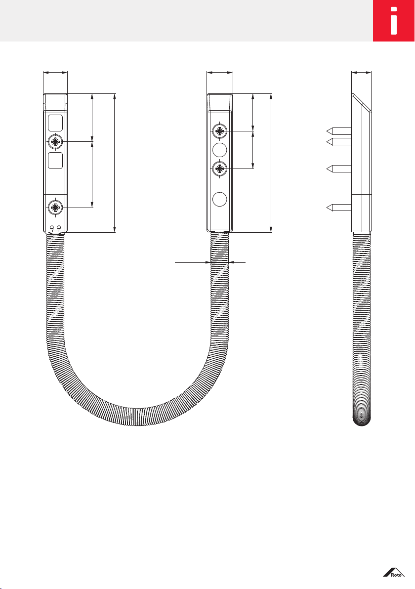
The model M 13 40(619 587) detachable cable
junction is used to cover the transition from supply
lines in the window or balcony door rebate. The
simple disconnection of the cable junction via the
connector in the rebate area enables the sash to be
removed.
The minimal space requirement permits installation
at many points in the rebate area. With the window
closed, concealed installation in the window rebate
prevents access to the cable junction.
And the integrated tamper circuit (opening
monitoring ) enables monitoring of the plugged-in
connection. Opening of the connector is signalled by
the alarm control panel. In addition, the connector is
also mechanically fixed in place with a screw. With
the alarm-glass connection socket (AGV) at the other
end of the cable of the cable junction, alarm glasses
can be connected directly to the cable junction.
Information on the product
Detachable miniature cable junction with alarm-glass connection socket

Subject to change. Roto E-Tec Cable junctions IMO_229_EN_v0.July 2012
.7
Technical specifications
Cable plug LiF9Y11Y 6 x 0.14mm2 4.9mm dia., white
Cable socket LiY11Y 4 x 0.14mm2 3.2mm dia., white
Cable length on socket side, outside of spiral 0.33m
Cable length on plug side 6 m
Protection type in accordance with DIN40050 IP67 (when plugged in)
Max. voltage 48VDC
Max. current 0.5A
Temperature range when moving -5°C to + 50°C
at rest -25°C to + 70°C
Environmental grade in accordance with VdS2110
III
VdS approval number G108094
Information on the product
Detachable miniature cable junction with alarm-glass connection socket
Technical specifications

8
.July 2012
.IMO_229_EN_v0 Roto E-Tec Cable junctions Subject to change.
Delivery scope of model M 1334 detachable
miniature cable junction (mat. no. 619 586)
6-pin plug unit in PVC housing moulded with
connection cable
6-pin socket unit in PVC housing moulded with
assembled VA metal spring and connection cable
End piece for installation of the VA metal spring
4 each A2 fastening screws, DIN7982
(2.9 x 19mm)
Installation instructions
Delivery scope of detachable miniature cable
junction with alarm-glass connector
Model M 1340 (mat. no. 619 587)
6-pin plug unit in PVC housing moulded with
connection cable
6-pin socket unit in PVC housing moulded with
assembled VA metal spring and connection cable
with AGV socket
End piece for installation of the VA metal spring
4 each A2 fastening screws, DIN7982
(2.9 x 19mm)
Installation instructions
Information on the product
Scope of delivery

Subject to change. Roto E-Tec Cable junctions IMO_229_EN_v0.July 2012
.9
10.4 11 8.5
20.528
59
16
16
59
Ø 7.5
Information on the product
Dimensions

10
.July 2012
.IMO_229_EN_v0 Roto E-Tec Cable junctions Subject to change.
Due to the large number of profiles and hardware available on the market,
nogenerally applicable information on mounting can be provided, as these
systems differ in several dimensions. Pleasecheck the mounting location and
the available space in the rebate area before the start of mounting.
Mounting location: Window or balcony door rebate
The operation of the connector is restricted to a maximum of 10 plugging
cycles.
Avoid torsion (cable twist) over the entire length of the cable, especially in the
metal spring.
The connector has an anti-twist protection against the danger of polarity
reversal;nevertheless the correct polarity must be ensured prior to each
plugging cycle.
The connector must never be operated when soiled or damp.
7mm dia. drilled holes for cable routing. Deburr drilled holes and check for
chips.
In addition to the generally valid state of technology, particular attention must
be paid to the following sets of technical rules: VDS2311, VDE0100
NOTE!
Install the detachable U-shaped cable junction (see fig.) so that the sash
can be turned open far enough (> 90°).
NOTE!
Leave a cable loop on the permanently mounted end of the spiral
(notthe plug end). This ensures that the cable in the cable junction has
sufficient freedom of movement if necessary when the window or the
door is opened.
Mounting
Advice

Subject to change. Roto E-Tec Cable junctions IMO_229_EN_v0.July 2012
.11
1.
7 mm dia. hole
through the frame
28 12.5
15 7 16
6
Ø7
Sash
component
Frame
component
2.
Mill elongated hole
(6 x 21 mm) through
the hardware groove
up to the glazing
rebate.
NOTE!
With timber windows, it may be necessary to create a pocket for
fastening the cable junction in order to enlarge the installation space
inthe rebate.
NOTE!
The drilling holes must be free of burrs and chips.
Mounting
Preparation for mounting

12
.July 2012
.IMO_229_EN_v0 Roto E-Tec Cable junctions Subject to change.
Mounting
Cable junction
1.
Guide the cable through the frame.
1
Fig.: Mounting on plug end
2.
Fasten plug end with screw
1
.
3.
Guide the cable with the end for the
alarm glass through the sash.
2
3
Fig.: Mounting fastening strip
4.
Fix the end of the spring in place in
the fastening strip and fasten it with
the screws
2
and
3
in the hard-
ware groove.
NOTE!
Only screw in screws by hand.
Pre-drilling of the screw holes
is recommended.

Subject to change. Roto E-Tec Cable junctions IMO_229_EN_v0.July 2012
.13
Mounting
Cable junction
5.
Hinge the sash and produce the
plug-and-socket connections.
Fig.: Mounting connector
NOTE!
Watch the anti-twist protection
of the connector!
Insulate the wires of the cable
not used!
6.
Secure the connector with the
screw
4
.
Fig.: Mounted cable junction
4
NOTE!
Only screw in screws by hand.

14
.July 2012
.IMO_229_EN_v0 Roto E-Tec Cable junctions Subject to change.
Mounting
Determining connection assignment
Detachable miniature cable junction with alarm-glass connection socket
NOTE!
To determine the connection assignment, the cable junction must not
be connected to either the alarm-glass connection socket or the loose
end of the cable.
Determine the connection assignment:
Mount the cable junction; this closes the tamper circuit.
Determine the corresponding wires of the tamper circuit on the loose end of
the cable with the circuit continuity tester/resistance tester (measured value
approximately 0 Ω) and mark (e.g. by twisting).
For easier measuring, bridge the two centre contacts of the alarm-glass
connection socket
Determine the corresponding wires on the loose end of the cable (measured
value approximately 0 Ω) with the circuit continuity tester/resistance tester
and mark; these form the peak connection.
The two remaining wires form the signal line.
Remove the bridge at the alarm-glass connection socket.
Peak connection
Tamper
circuit
Loose end of cable Alarm-glass connection socket
Alarm system
Signal line

Subject to change. Roto E-Tec Cable junctions IMO_229_EN_v0.July 2012
.15
Mounting
Dismantling
1.
Loosen screw
4
and remove.
4
Fig.: Dismantling
2.
Separate connector with Allen key
or suitable screwdriver.
NOTE!
Do not pull on the spring to
separate the connector.
Otherwise the spring will be
damaged.
3.
Remove the sash.
4.
Protect connector against dust and
moisture.

16
.July 2012
.IMO_229_EN_v0 Roto E-Tec Cable junctions Subject to change.
The stainless-steel accessories with a brushed surface were developed especially
for installation of detachable miniature cable junctions in timber, PVC and
aluminium windows and balcony doors.
Cover plates
For timber (mat. no. 619 588)
For PVC and aluminium (mat. no. 619 589)
The cover plates are used to cover milled areas and drilled holes. With timber
windows and balcony doors, an oblong hole (see page 18 for dimensions) must
be milled. With PVC windows and balcony doors, the cover plate fits in the
standardised profiles of popular suppliers.
Mounting box
The mounting box is used to provide sufficient space for the cable junction if
theclearance is not sufficient. Prior to installation including the cable junction,
apocket (see page 19 for dimensions) must be milled.
Accessories
Cover plates, mounting box
Mat. no. 619
585

Subject to change. Roto E-Tec Cable junctions IMO_229_EN_v0.July 2012
.17
16
110
126
42
110
126
42
16
180
210
67.5
25
20
1
Cover plate for
timber
Installation accessories
Description Mat. no. Material Dimensions (W x H x D) Scope of delivery
Cover plate for timber 619 588 Stainless
steel
16 x 126 x 3 mm 1 cover plate
2 screws, M 3 x 12 mm
2 screws, 3.5 x 25 mm
Cover plate for
PVC, aluminium
619 589 Stainless
steel
16 x 126 x 3 mm 1 cover plate
2 screws, M 3 x 12 mm
2 screws, M 4 x 6 mm
2 screws, 3.5 x 25 mm
Mounting box 619 585 Stainless
steel
20 x 180 x 25 mm 1 mounting box
2 screws, M 3 x 12 mm
2 screws, M 4 x 6 mm
2 screws, 3.5 x 25 mm
Cover plate for
PVC, aluminium
Mounting box
Accessories
Cover plates, mounting box
Dimensions & delivery scope

18
.July 2012
.IMO_229_EN_v0 Roto E-Tec Cable junctions Subject to change.
16
110
126
Depth 3 mm
Cover plate for timber
Cover plate for PVC, aluminium
Accessories
Installation drawings for cover plates

Subject to change. Roto E-Tec Cable junctions IMO_229_EN_v0.July 2012
.19
Mounting box for timber
Mounting box for PVC, aluminium
Accessories
Installation drawings for mounting box
Depth
30 mm
Depth
30 mm
Depth
1 mm

MTS / textract Dated: July 2012. Subject to change. IMO_229_EN_v0
© 2012 Roto Frank AG ® Roto is a registered trademark
Roto Frank AG
Window and door technology
Wilhelm-Frank-Platz 1
D-70771 Leinfelden-Echterdingen
Telephone +49 711 7598 0
Telefax +49 711 7598 253
www.roto-frank.com
From a single source: The optimum hardware system to meet all challenges
Roto E-Tec |Electronic drive and control systems for windows and doors
Roto NT | The world’s biggest selling Tilt&Turn hardware system
for windows and balcony doors
Roto Patio | Hardware systems for large sliding windows and doors
Table of contents
Other Roto Door Opening System manuals