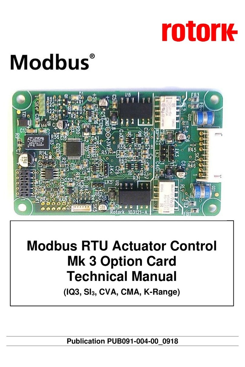
rotork Mk3 User manual

Publication PUB089-005-00_0618
Mk3 Foundation Fieldbus
Option Card
Technical Manual

Foundation Fieldbus CP Option Card Technical Manual
2 of 116 Publication PUB089-005-00_0618
Note 1: Throughout this manual the Foundation Fieldbus may be abbreviated to FF
Note 2: Throughout this manual the FF Interface Card may simply be referred to as the FF CP card.
Note 3: The information in this manual relates to the FF CP card firmware / hardware versions:
M3.1 / T1.4 / H1.1 (or newer)
Note 4: The screen dumps used in the manual have generally be taken from a National Instruments FF
configurator tool’s screen. Other configurator tools may show the same data on a different set of
screens.
Note 5: This manual is to be used in conjunction with the relevant actuator setting manual and assumes a
pre-existing level of knowledge of using both FF and the particular actuator type. It is advised that
the relevant technical manual is read before attempting to set-up FF within the actuator.
Note 6: The FF CP card described in this manual contains static-sensitive devices. Suitable
precautions, such as wearing an earthed anti-static wrist strap, should be taken before
handling the card. It should be kept in an anti-static bag or box while it is not fitted within an
actuator.
As we are continually developing our products their design is subject to change without notice.
©The contents of this document are copyright and must not be reproduced without the written permission
of Rotork.
The name Rotork is a registered trademark.
Foundation is a registered trademark of the Fieldbus Foundation.
NI-FBUS is a registered trademark of National Instruments.
Windows is a registered trademark of The Microsoft Corporation.
The names; Allen, Bluetooth, Modbus, Rotork and Torx are registered trademarks.

Contents
Publication PUB089-005-00_0618 3 of 116
Contents
Glossary of Terms:.........................................................................................................................6
Abbreviations used: .......................................................................................................................8
Supporting Documents:.................................................................................................................8
1INTRODUCTION................................................................................................ 9
2 FF CARD PROPERTIES ................................................................................. 11
2.1 Mechanical properties........................................................................................................11
2.2 Electrical properties...........................................................................................................12
2.3 Operation and storage .......................................................................................................12
3FITTING THE FF CP CARD ............................................................................ 13
3.1 Inside a Rotork Actuator..................................................................................................13
3.1.1 Inside an IQ3/IQT3 actuator...............................................................................13
3.1.2 Inside an SI3actuator .........................................................................................15
3.1.3 Inside a CVA actuator.........................................................................................16
3.1.4 Inside a CMA actuator........................................................................................17
3.1.5 Inside a K range actuator ...................................................................................18
3.1.6 Inside a CK actuator...........................................................................................19
3.2 Replacing or Fitting an FF CP Option Card.....................................................................20
3.3 Socket, LED and Jumper functions of the FF card.........................................................21
4 IEC 61158 DATA HIGHWAY AND CONNECTIONS....................................... 23
4.1 Data highway ......................................................................................................................23
4.2 Fieldbus power supply.......................................................................................................24
4.3Termination network..........................................................................................................26
5THE ACTUATOR INPUT AND OUTPUT SIGNALS........................................ 27
5.1 Controls...............................................................................................................................28
5.1.1 Controls priority ..................................................................................................31
5.1.2Foundation control using DO blocks only...........................................................32
5.1.3 Foundation control using the AO block only.......................................................32
5.1.4 Foundation control using both DO and AO blocks.............................................33
5.1.5 The ‘S’ contacts (RLY 1 to RLY 4) controlled by the DO blocks ........................34
5.1.6 Foundation network control disable feature .......................................................34
5.2 Discrete Input status feedback .........................................................................................35
5.2.1 Discrete Inputs....................................................................................................36
5.2.3 Discrete Inputs reporting the FF CP card condition ...........................................40
5.3 Actuator Analogue Input feedback...................................................................................41

Foundation Fieldbus CP Option Card Technical Manual
4 of 116 Publication PUB089-005-00_0618
6FUNCTION BLOCKS ...................................................................................... 43
6.1 Resource Block ..................................................................................................................44
6.2 Transducer Block ...............................................................................................................47
6.2.1 Transducer block parameters.............................................................................47
6.2.2 Changing the settings in the Transducer block..................................................53
6.2.3 Editing the Foundation specific parameters 1-23 and 99...................................54
6.2.4 Editing the actuator setup parameters 50-67.....................................................54
6.2.5 Editing the control parameters 65 - 66 ...............................................................59
6.3 Analogue Input blocks.......................................................................................................60
6.4Discrete Input blocks .........................................................................................................61
6.5 Analogue Output block......................................................................................................63
6.6 Discrete Output blocks ......................................................................................................65
6.6.1 Multiple block –single bit control........................................................................66
6.6.2 Single block –multiple bit control.......................................................................66
6.7 PID Control block ...............................................................................................................68
6.8 Control Selector block .......................................................................................................69
7 LINK ACTIVE SCHEDULER (LAS)................................................................. 71
7.1 Creating a schedule ...........................................................................................................74
7.2 Connecting the blocks.......................................................................................................75
7.3 Downloading the schedule................................................................................................75
7.4 Optimising the downloaded schedule..............................................................................76
8. SETTING UP THE FF CP CARD (QUICK START GUIDE)............................. 77
8.1 Setting up with the Setting Tool .......................................................................................78
8.2 Insight 2...............................................................................................................................79
8.3 Methods...............................................................................................................................81
8.4 Control output function block settings............................................................................82
8.4.1 Analogue Only control........................................................................................83
8.4.2 Discrete Only control ..........................................................................................83
8.4.3 Mixed Analogue and Discrete control.................................................................84
8.4.4 Hard-wired inputs - Aux Input Function..............................................................84
8.5 Status feedback function block settings .........................................................................85
8.5.1 Analogue position and torque data.....................................................................85
8.5.2 Discrete Input data .............................................................................................85
8.6 Default settings...................................................................................................................86
8.7 Using the DTM (with FDT)..................................................................................................87
9THE FF CP CARD FIRMWARE AND DD FILES............................................. 89
9.1 Firmware..............................................................................................................................89
9.2 Device Description Files....................................................................................................89

Contents
Publication PUB089-005-00_0618 5 of 116
APPENDIX A –HANDLING FAULT CONDITIONS................................................. 91
APPENDIX B –FUNCTION BLOCK MODE –LO................................................... 92
APPENDIX C –PID APPLICATION. ....................................................................... 93
APPENDIX D –ITK6 FF SPECIFICATION DATASHEET....................................... 96
D.1 Basic Fieldbus Function Blocks.......................................................................................96
D.2 Channel Allocation.............................................................................................................96
D.3 Segment Information..........................................................................................................97
APPENDIX E –NAMUR NE 107 - GUIDELINES FOR SETTING UP...................... 98
E.1 Background info:................................................................................................................98
E.2 Test set up for FD_...._ACTIVE: ......................................................................................101
E.3 Test set up for FD_...._ALM:............................................................................................104
APPENDIX F –CHANGING THE ITK REVISION.................................................. 106
APPENDIX G –DTM.............................................................................................. 110
APPENDIX H –HOST INTEROPERABILITY SUPPORT TEST (HIST)................ 113
APPENDIX I –COMMON PROBLEMS ................................................................. 114

Foundation Fieldbus CP Option Card Technical Manual
6 of 116 Publication PUB089-005-00_0618
Glossary of Terms:
Automatic (AUTO) A possible mode of a function block which means the block runs its
algorithms, producing data at its inputs or outputs.
Basic Device A basic device is any device not having the capability to control
communications on an H1 fieldbus segment.
Back calculation output This parameter is available on output function blocks, and provides a
(BKCAL_OUT) feedback mechanism to control blocks such as PID.
Capabilities File A file describing the communication objects in a fieldbus device. A
configuration device can use Device Description (DD) Files and
Capabilities Files to configure a fieldbus system without having the
fieldbus devices online.
Cascade (CAS) A possible mode of a function block which refers to an input derived
from the output of another function block.
Device Description (DD) A machine-readable description of all the blocks and block parameters
of a device.
Fieldbus The digital, two-way, multi-drop communication links.
Fieldbus Interface Card (FIC) The option card fitted to the actuator which provides the
communications interface between the DCS and the actuator.
Function Block (FB) Also known as standard function block. This is a named block
consisting of one or more inputs and outputs. These are built into
fieldbus devices to achieve the desired control functionality. The FF
CP has Analogue Input (AI), Analogue Output (AO), Digital Input (DI),
Digital Output (DO), Control Selector (CS) and PID control (PID).
H1 A term used to describe a FF highway operating at 31.25 kbit/sec.
Initialization Manual (IMAN) The forward path to a physical output is broken and the output is
tracking the downstream block. This will result in the control action
being suspended.
Interoperability The capability for a device from one manufacturer to interact with that
of another manufacturer, on a fieldbus network, without loss of
functionality.
Input / Output Options This parameter is contained within output function blocks and
(IO_OPTS) allows different parameters to appear at various connection points.
Link Active Scheduler (LAS) One Link Master (LM) device functions as the fieldbus LAS at any one
time. The LAS is the Fieldbus device that is currently controlling
access to the Fieldbus. A device that is responsible for keeping a link
operational. The LAS executes the link schedule, circulates tokens,
distributes time, and probes for new devices.

Contents
Publication PUB089-005-00_0618 7 of 116
Local Override (LO) A possible mode of a function block where the block can only be
monitored, and no changes can occur to its set points.
Manual (MAN) A possible mode of a function block where the final element is
manually input by a user, as opposed to being controlled by its
algorithms.
Out Of Service (OOS) A possible mode of a function block which means the block does not
run its internal algorithms and cannot be used.
Process Variable (PV) A process variable is a condition of the process fluid (a liquid or gas)
that can change the manufacturing process in some way. Common
process variables include pressure, temperature, flow rate, etc.
Readback This is the parameter in an output function block which indicates the
actual feedback of a process, as opposed to the desired value.
Remote Cascade (RCAS) A possible mode of a function block which refers to an input derived
from non-function block outputs.
Resource Block (RB) A block that describes the characteristics of the fieldbus device such
as; the device name, manufacturer and serial number.
Schedules Communication events that occur at the same time during each
control cycle. The schedule defines when Function Blocks (FBs)
execute and when data / status information is published on the bus.
Segment A Foundation Fieldbus network is made up of devices connected by a
serial bus. This serial bus is called a segment (also known as a link).
A section of an H1 fieldbus that is terminated in its characteristic
impedance. Segments can be linked by Repeaters to form a longer
H1 fieldbus. Each Segment can include up to 32 H1 devices.
Transducer Block (TB) A block that is an interface to the physical, sensing hardware in the
device. It also performs the digitising, filtering, and scaling
conversions needed to present input data to function blocks, and
converts output data from function blocks. The block decouples the
Function Blocks from the local input/output (I/O) functions required to
read the limit switches and command the actuator to move.
Virtual Communication Preconfigured or negotiated connections between virtual field devices
Relationship (VCR). on a network. The quantity of VCRs able to be handled by an H1
gateway, or Link Master usually determines the number of devices on
an FF highway.
Virtual Field Device (VFD) The virtual field device is a model for remotely viewing data described
in the object dictionary. The services provided by the Fieldbus
Messaging Specification allow you to read and write information about
the object dictionary, read and write the data variables described in
the object dictionary, and perform other activities such as uploading or
downloading data and invoking programs inside a device.

Foundation Fieldbus CP Option Card Technical Manual
8 of 116 Publication PUB089-005-00_0618
Abbreviations used:
AI Analogue Input (Blocks AI1, AI2)
AO Analogue Output (Block A0)
BTST Bluetooth Setting Tool
CFF Common File Format
Comms Communications
CP Common Protocol
CS Control Selector Block
DCS Distributed Control System
DD Device Description
DI Digital Input (Blocks DI1, DI2, DI3, DI4, DI5)
DO Digital Output (Blocks DO1, DO2, DO3, DO4)
DSM (Actuator) Digital Switch Mechanism
DTM Device Type Manager
ESD Emergency Shut Down
FB Function Block
FDT Field Device Tool
FF Foundation Fieldbus
FIC Fieldbus Interface Circuit
HIST Host Interoperability Support Test
ITK Interoperability Test Kit
LAS Link Active Scheduler
LM Link Master
MSM (Actuator) Mechanical Switch Mechanism
NIC Network Interface Circuit
PCS Process Control System
PDA Personal Digital Assistant
PID Proportional, Integral, Derivative; A type of function block which refers to a closed
loop control algorithm
PST Partial Stroke Test
RAM Random Access Memory
RB Resource Block
ROM Read Only Memory
SW Software
TB Transducer Block
VCR Virtual Communication Relationship
Supporting Documents:
Available from the Fieldbus Foundation, Austin, Texas
Technical Overview of Foundation Fieldbus FD-003 (all parts).
Wiring and Installation 31.25 kbit/s, AG-140

Introduction
Publication PUB089-005-00_0618 9 of 116
1 INTRODUCTION
This manual is designed to be an aid to commissioning and will assist with achieving a
successful integration of Rotork’s FF product into a DCS’s FF network. Correct installation
should ensure a lifetime of trouble free use. This is not a manual on how to use FF. Due to the
complex nature of the protocol, Rotork strongly recommends users attain a sufficient level of
FF competency prior to attempting any FF commissioning work.
The FF CP option card is the third evolutionary step in Rotork’s Foundation Fieldbus journey. It has
been certified as conforming to the open fieldbus standard IEC 61158 and is suitable for use on an FF
H1 highway. The H1 highway uses two copper wires to both to carry the digital messages and to
supply power to all the devices connected on the highway. As such it is necessary to have a suitable
power supply and termination filter on the highway for the FF nodes to function.
The current version of the FF card may be fitted into any of the current Rotork Controls’ actuator
product range. The FF card is an integral part of the actuator in which it is housed and is fitted within
the main electrical housing. This electrical housing need never be opened once the actuator leaves
the assembly plant. All adjustments to the settings for the FF card may be made via the Foundation
data highway using a suitable network configuration tool. There is no external marking on the actuator
to show the FF card serial number since the whole module may be replaced if it should fail.
The FF card’s circuits do not impinge on the actuator control electronics; the actuator itself remains
fully self-protecting. The card performs the tasks of IEC 61158 interface, actuator data collection and
the issuing of actuator commands.
The FF CP card may command the actuator into which it is fitted to open, stop, close, perform an ESD
operation, perform a partial stoke operation or move to a set position. Commands to the module come
from the network and may be generated in another actuator or device on the network using peer to
peer, publisher/subscriber communication. Additionally, digital and analogue status information
relating to the actuator is published for the other devices to read.
For a quick start guide see section 8.
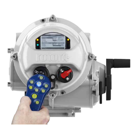
Fig 1.1: Some of the actuators which use the FF CP card

Foundation Fieldbus CP Option Card Technical Manual
10 of 116 Publication PUB089-005-00_0618
1.1 General
The FF CP card is capable of performing the following functions:–
a) Link Master / Link Active Scheduler
b) Basic Device
The in-built function blocks vary in availability between the different actuator types. The input and
output blocks are used to link to the transducer block and tie to the available actuator functions. For
example the AI block associated with actuator torque measurement is only available in the DSM
actuator type. The following table lists the function blocks and their related availability in each actuator
type.
Function Block Type
Resource Block –System information
Transducer Block –Device configuration
Digital Inputs
DI 1 Closed limit or multistate
DI 2 Open limit or multistate
DI 3 Selector in remote or multistate
DI 4 General alarm or multistate
DI 5 Actuator moving or multistate
Digital Outputs
DO 1 Open or multistate
DO 2 Close or multistate
DO 3 Stop or multistate
DO 4 Single bit selectable or multistate
Analogue Inputs
AI 1 Analogue position feedback
AI 2 Torque / Thrust
Analogue Output
AO Desired position (set point command)
Controllers
PID (3 term controller)
Control Selector

FF CP Card Properties
Publication PUB089-005-00_0618 11 of 116
2 FF CARD PROPERTIES
2.1 Mechanical properties
The FF CP card consists of a single network interface card that fits directly to the main actuator control
PCB. It consists of two isolated parts, the actuator interface and the network interface
Network Interface
This carries the FF highway connections and the processor handling the data highway
communication and function blocks. The Network Interface contains the FF connector (SK3),
polarised to prevent incorrect insertion. This connects to the three wire loom routed to the
terminal compartment of the actuator. Power for the Network Interface is taken from the FF
highway.
Actuator Interface
The primary connection to the actuator circuits is by a multi-pin connector on the base of
Interface Card. The PCB design ensures it may only be fitted in the correct polarisation. The
Actuator Interface on the FF CP card is powered from within the actuator.
Network Connector
Fig 2.1: The FF card, showing the network connector

Foundation Fieldbus CP Option Card Technical Manual
12 of 116 Publication PUB089-005-00_0618
2.2 Electrical properties
The FF CP card does not sit in the main control path for the actuator and does not affect the actuator
control integrity.
Internally stored programs control the processors on the module. The Network Interface processor
software may be updated by connecting a suitable test cable and loading the new code directly, but
this cannot be done in the field The FF system allows all settings for the data highway and module
communication functions to be held in non-volatile memory on the Network Interface Card.
The FF data highway connection is fully isolated from the actuator electronics.
2.3 Operation and storage
The Module is designed to be stored in the actuator and operated within the same environment as the
actuator.
The constraints are:
Operating temperature: -40oC to +70oC
Storage temperature: -50oC to +85oC
Relative Humidity: 5% to 95% (<50oC) non-condensing
Refer to actuator manuals for range applicable for the particular actuator type.

Fitting the FF CP card
Publication PUB089-005-00_0618 13 of 116
3 FITTING THE FF CP CARD
3.1 Inside a Rotork Actuator
3.1.1 Inside an IQ3/IQT3 actuator
The FF CP card is suitable for fitting into IQ3 actuators. When factory-fitted, their wiring diagrams will
contain an ‘F’, e.g. 100F2000. The FF CP can be located in one of 2 or 4 option ‘slots’ located on the
back of the control module PCB, housed in the electrical cover. There are 2 slots for directly
connecting the option module to the control module and where those slots are already filled, the option
card can be fitted on top of the existing modules. The modules can be stacked 2 high where a ‘deep’
electrical cover is fitted.
Back of the control module
Fig 3.1: The FF CP card’s location behind the control module in an IQ3
With the IQ3 actuators, the remote inputs are always present (they are conditioned by the control
board) and there is an option to include Digital Outputs from relay contacts. If the FF CP is required to
operate the 4 digital outputs that can be controlled from the card, then an Extra Relay Indication card
associated with these outputs must be fitted into another option slot in the actuator.
The FF CP is connected to the control module by a 10 way header (SK2). The wiring harness from the
actuator terminal bung connects the FF H1 highway field connections to SK3.
Option Slots

Foundation Fieldbus CP Option Card Technical Manual
14 of 116 Publication PUB089-005-00_0618
Replacing or Fitting an FF CP Option Card
The FF CP card should be replaced or fitted only in a suitable environment. The actuator must be
made electrically safe before opening any covers. The electrical housing cover should be removed
after unscrewing the four 6mm Allen machine screws. Unplug the electrical housing loom from the
control board and remove the cover. Unplug the grey ribbon cable from the edge of the control board
and unplug the black plastic carrier frame from the frame legs. Unplug the loom from the FF card.
Unscrew the Torx 20 screws holding the FF card into the frame and carefully unplug the FF card from
the control board. The replacement board is fitted in the reverse order to removal. The wiring harness
connectors are polarised so that only the correct one will fit its mating part on the circuit boards. Don’t
forget to re-connect the grey ribbon cable to the edge of the control board.
If the operation is to fit an FF CP card for the first time, then the necessary wiring loom must be added
to the internal wiring harness of the actuator. The actuator wiring diagram shows the connectors and
harness used. The wiring harness is fitted inside the actuator before attempting to fit the FF CP. This
requires that you remove the terminal bung, which is held in place by a large circlip. Be careful to
attach the wiring loom to the correct terminals, which are numbered. Re-fit the terminal bung.
Once the loom is in place, connect it to the FF CP, then fit the FF CP to the actuator main board
connector. Attach the FF CP to the frame, using the Torx 20 screws.
Once the module is fitted, the actuator should be re-assembled.
Once power is applied, the field unit parameters should be checked and corrected, where necessary.
Some FF TB parameters can be set and adjusted either by using the Infra-red and Bluetooth setting
tools or by Insight 2 using Bluetooth. The parameter setting procedure is covered by the IQ3 Full
configuration, status and monitoring user manual, PUB002-040-00, available on the Rotork web site,
www.rotork.com

Fitting the FF CP card
Publication PUB089-005-00_0618 15 of 116
3.1.2 Inside an SI3actuator
The FF CP is suitable for fitting into SI3actuators. When factory-fitted, the network connections will be
as in the diagram below:
Fig 3.2: The SI3highway interface connection table
The internal layout of the actuator will be similar to that of the IQ3, when considering installation of the
FF CP, as above.

Foundation Fieldbus CP Option Card Technical Manual
16 of 116 Publication PUB089-005-00_0618
3.1.3 Inside a CVA actuator
The FF CP is suitable for fitting into CVA actuators. When factory-fitted, the wiring diagram will be
CXX-80 (where X can be any value). This details the option card connections to the terminal bung.
The FF CP module is fitted in the only option board slot inside the CVA electrical housing - on the
underside of the Main PCB assembly. The FF CP should be replaced or fitted only in a suitable
environment.
Fig 3.3: The FF CP located on the underside of the control PCB in a CVA actuator
To fit an FF CP card, begin by removing power from the actuator and wait until the LED on the
selector knob stops illuminating. This may take several minutes if a reserve power pack of capacitors
is fitted.
Remove the six M10 machine screws from the upper cover and lift it off carefully, while removing its
ribbon cable connector from the socket on the Main PCB.
Remove the various wiring looms from the sockets on the edges of the Main PCB, noting carefully
where they attach. Each connector is different to avoid error.
Remove the Main PCB in its plastic chassis by gently pushing the chassis legs inwards to release
them from a groove in the actuator housing.
Fit the FF CP to the underside of the Main PCB using the hardware supplied with the FF CP card.
The wiring loom from the actuator terminal bung connects the FF H1 field connections to SK3. If a new
card is being fitted as an upgrade, then the actuator will need to have the loom fitted. Remove the
terminal bung by removing the circlip and gently pulling the bung. Attach the loom and replace the
bung.
The FF CP is connected to the control module by a header, SK2.
The FF CP in the CVA must be enabled. This would usually be done during factory test, but may be
required to be completed on site for conversions to FFs or if a replacement card is fitted. To enable
the card, the Rotork PDA software Enlight (downloadable from the Rotork web site) is required to be
used to change parameter 34. It must be read and then have 2048 decimal added to it.
This procedure is best performed by a Rotork Engineer.

Fitting the FF CP card
Publication PUB089-005-00_0618 17 of 116
3.1.4 Inside a CMA actuator
The FF CP is suitable for fitting into CMA actuators, wiring diagrams MXX-FX (where X can be any
value) detail the option card connections on the terminal strip. The FF CP module is fitted in the only
option board slot inside the CMA electrical housing.
Fig 3.4: The FF CP located in a CMA actuator
The FF CP should be replaced or fitted only in a suitable environment. The actuator must be made
electrically safe before opening any covers. The electrical housing cover should be removed after
unscrewing the four 6mm Allen machine screws.
The FF CP should be fitted in the position shown in the illustrations above. It plugs into the control
board at the 10-way header, which is SK2 on the FF CP board. There is a wiring loom which brings
the FF H1 network connection to SK3 on the FF CP.
Connection details are shown in the illustrations on the next page.
The CMA actuator will need configuring, so that it is aware that control from the field is through the FF
CP card. This is done by accessing the menu structure as shown in the CMA Installation and
Maintenance manual, PUB094-003, found on the Rotork web site.
Option location

Foundation Fieldbus CP Option Card Technical Manual
18 of 116 Publication PUB089-005-00_0618
3.1.5 Inside a K range actuator
The FF CP is suitable for fitting into K-Range actuators; wiring diagrams similar to 1612ZFD detail the
option card connections. The FF CP module is fitted in the only option board slot inside the K-Range
electrical housing.
SK2 on the FF CP card plugs directly onto SK9 on the Main card, while a terminal bung loom brings
the FF highway signals to SK3.
FF Option Card
Main Card
Fig 3.5: The FF card located in a K-Range actuator
The FF card should be replaced or fitted only in a suitable environment. The actuator must be made
electrically safe before opening any covers. The electrical housing cover should be removed after
unscrewing the four 8mm Allen machine screws.
The FF card is attached to the main card by three plastic pillars, with one metal pillar, Torx 20 screw
and a fibre washer; as shown in the illustration above.
If an actuator is having the FF fitted for the first time, then the terminal bung loom must also be fitted.
The terminal numbers will be found in the appropriate wiring diagram, which should be included in the
fitting kit.

Fitting the FF CP card
Publication PUB089-005-00_0618 19 of 116
3.1.6 Inside a CK actuator
The FF CP card is suitable for fitting into CKC/ CKRC actuators with Px5xxxxx and Kx5xxxxx series
wiring diagrams. The connections and fitting in a CKRC are the same as the CKCso the following
information effectively relates to both actuator types. The FF CP card is normally located in the first
option board slot inside the electrical housing, using Main PCB connection SK2.
The Interface card must be correctly profiled and loaded with the appropriate connectors to match the
actuator. The illustration below shows the location of the cards in the Centronik unit.
Within the actuator the remote inputs are always present (they are conditioned by the FF CP card) and
there is an option to include Digital Outputs from relay contacts. If the FF CP card is required to
operate the 4 digital outputs that can be controlled from the card, then the Extra Relay Indication card
associated with these outputs must be fitted into the actuator. The following table describes the wiring
harnesses and their function in the Centork actuator.
FF card Socket
Wiring Harness
SK2
Power and CANbus from actuator.
SK3
FF H1 highway connection.
Fig 3.6: The FF CP card located in a Centronik unit.
Option Card Location

Foundation Fieldbus CP Option Card Technical Manual
20 of 116 Publication PUB089-005-00_0618
3.2 Replacing or Fitting an FF CP Option Card
The FF card should be replaced or fitted only in a suitable environment. The actuator must be made
electrically safe before opening any covers.
Warning: Removal of certain covers will void warranty, it is advised that a Rotork approved
engineer perform this function.
Suitable anti-static precautions should be taken, as the actuator circuitry contains static-sensitive
components.
If an upgrade kit has been purchased please carefully follow the instructions given in the
documentation provided. It will also be necessary to have the relevant actuator maintenance manual
to hand when adding a new card.
The electrical housing cover should be removed and the existing FF card carefully unplugged from its
main connector. The Interface card will be attached to the Main PCB mounting ring by four screws,
which are T20 (or T15 if two cards are present). Once removed from the main connector the wiring
loom connectors should be removed. The replacement board is fitted in the reverse order to removal.
The wiring harnesses are polarised so that only the correct one will fit its mating part on the circuit
board.
If the operation is to fit an FF card for the first time then the necessary wiring looms must be added to
the internal wiring harness of the actuator. The actuator wiring diagram shows the connectors and
harnesses used. The wiring harnesses are fitted inside the actuator before attempting to fit the FF
card. Once the looms are in place connect them to the FF card, then fit the card to the actuator control
board/main board connector.
Once the module is fitted the actuator should be re-assembled. If an option card is fitted into an
actuator after it has left the factory then the actuator needs to be set-up to use this card in the
software, the card will not do anything until this has been done. This can be done using the local HMI
or Insight but ideally needs to be done by a Rotork service engineer. This is not necessary if a card is
being replaced with the same type of card, e.g. replacing an FF with a new FF card.
It is advisable to check the software version numbers are the same between the new and old card to
ensure consistent operation. It is also advisable to check the ITK revision of the old FF card as it may
be necessary to modify the new FF card’s ITK revision. If this needs to be done, see Appendix F.
Table of contents
Other rotork Control Unit manuals
Popular Control Unit manuals by other brands

Bitspower
Bitspower Summit M Pro Crystal instruction manual

Teufel
Teufel ControlStation 2 Technical description and operating instructions

GEZE
GEZE MBZ300 installation instructions

Janus
Janus 910CF user guide

Mitsubishi Electric
Mitsubishi Electric A1SD75P1-S3 user manual

Velleman
Velleman VMA349 user manual