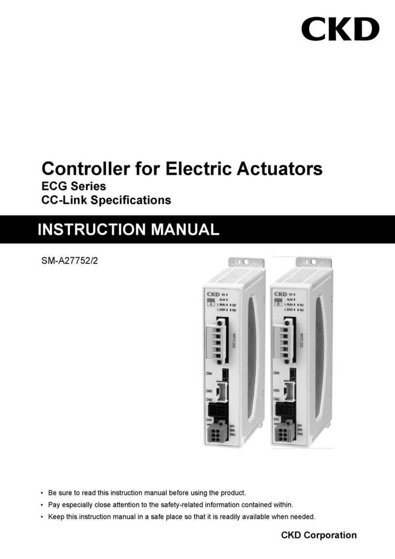
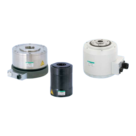
CKD LN Series User manual

RRC
GRC
RV3*
NHS
HR
LN
FH100
HAP
BSA2
LHA
LHAG
HKP
HEP
HCP
HMF
HMFB
HFP
HLC
HGP
FH500
HBL
HDL
HMD
HJL
BHE
CKG
CK
CKA
CKS
CKF
CKJ
CKL2
CKH2
CKLB2
FJ
FK
Ending
HLA/
HLB
HLAG/
HLBG
CKL2
-*-HC
NCK/
SCK/FCK
BHA/
BHG
212 213
RRC
GRC
RV3*
NHS
HR
LN
FH100
HAP
BSA2
LHA
LHAG
HKP
HEP
HCP
HMF
HMFB
HFP
HLC
HGP
FH500
HBL
HDL
HMD
HJL
BHE
CKG
CK
CKA
CKS
CKF
CKJ
CKL2
CKH2
CKLB2
FJ
FK
Ending
BHA/
BHG
HLA/
HLB
HLAG/
HLBG
CKL2
-*-HC
NCK/
SCK/FCK
Cylinder/hand with length measuring sensor
Length measuring function
50322016
20
or equivalent
25
or equivalent
1-5V voltage output
at double-jaw full
stroke
Analog output type
Switch/analog double
output display
12
1-5V voltage output
between random
8 mm in stroke
Analog output type
Switch/analog double
output display
Output type
ON-OFF output
with full double
jaw stroke length
Cylinder with LN
Applicable cylinder
Compact cylinder
Linear slide cylinder
Amplifier
separate type
Amplifier mounting
Bore size
(mm)
Stroke length
(mm)
Hand with LN
Incorporated hand
Compact cross roller parallel hand
Centering hand
Actuator variations with length measuring sensor (LN)
Applications of hand with length measuring sensor
Linear system Grasp system
Switch output type
New length measurement sensor installed on small cylinder and hand components.
Next-generation pneumatic components enabling simultaneous work on workpiece
(actuator function) and inspection (quality judgment, simple length measurement).
20
or equivalent
25
or equivalent
12
or
equivalent
16
or
equivalent
20
or
equivalent
50
or
equivalent
20, 30, 50
(Note)
Note: Stroke varies with the model. Contact CKD for linear tube diameters and strokes.
OUT
Resin molded, rubber, etc.
1-5V voltage and
switch output
between random
10 mm in stroke
1-5V voltage and
switch output at
double-jaw full
stroke
Indicator
Confirmation of workpiece grasping
Confirmation of deformed
workpiece grasping signal
Identification of workpieces with different shapes
LN-A* Series
LN-B* Series
BHE Series
BHA Series
BHG Series
This special new magnetic sensor
attains linear output for movement of the
piston with a magnet (PAT.P). This
sensor enables intermediate detection
and workpiece judgment functions that
the conventional cylinder switch never
achieved.
Cylinder with length measuring sensor
(Indicator type, analog output type)
Caulk and measure caulking
amount simultaneously
(What is the length measuring sensor?)
functions integrated actuator
Reduce inspection processes
Series version of display units
Making inspection easier and simpler
A display has been added for analog output.
This new display lets inspection results be directly
processed and displayed digitally, eliminating the
need for subsequent processes.
Simplifying conventionally difficult
intermediate detection (manual)
Simplifying conventionally difficult intermediate
detection (manual) sensor output is proportional to
actuator operation, so intermediate workpiece
prehension is detected, and corresponding to
workpiece transfer needs such as sorting of mixed
workpieces, detection of irregular workpieces, and
detection of abnormal prehension.
Simple adjustment with key operations
The switch operation point and movement range
are easily adjusted with key operation on the
display.
Wide selection of match applications with
more mounted models and bore sizes
Compatible mounted actuators have been
increased with the super compact cylinder SSD
Series, linear sliding cylinder LCS Series, cross
roller parallel hand BHA/BHG Series, and highly-
rigid centering hand BHE Series, enabling use with
many different applications.
Lead wire with improved elasticity
Amplifier separated for
all working environments
Indicator
RRC
GRC
RV3*
NHS
HR
LN
FH100
HAP
BSA2
LHA
LHAG
HKP
HEP
HCP
HMF
HMFB
HFP
HLC
HGP
FH500
HBL
HDL
HMD
HJL
BHE
CKG
CK
CKA
CKS
CKF
CKJ
CKL2
CKH2
CKLB2
FJ
FK
Ending
BHA/
BHG
HLA/
HLB
HLAG/
HLBG
CKL2
-*-HC
NCK/
SCK/FCK
Cylinder/hand with length measuring sensor
Length measuring function

RRC
GRC
RV3*
NHS
HR
LN
FH100
HAP
BSA2
LHA
LHAG
HKP
HEP
HCP
HMF
HMFB
HFP
HLC
HGP
FH500
HBL
HDL
HMD
HJL
BHE
CKG
CK
CKA
CKS
CKF
CKJ
CKL2
CKH2
CKLB2
FJ
FK
Ending
HLA/
HLB
HLAG/
HLBG
CKL2
-*-HC
NCK/
SCK/FCK
BHA/
BHG
214
Applications
Using a length measurement sensor with the compact cylinder lets
workpiece press-fitting be inspected with the length measurement
sensor's output while the workpiece is press-fitted with the
cylinder. Workpiece thickness is measured with the display. A line
is automated by retrieving determined signals in the PLC.
For the cylinder type, measurement length range is limited and set
at the factory to match the user's required detection position,
letting the system can be started by simply connecting wiring.
Clamping is controlled by retrieving the
cylinder piston stop position as length
measurement sensor output.
This is used to check whether the workpiece
is held correctly. The operating range is set
to narrow so that the sensor turns on only
when the workpiece is correctly grasped.
Small parts are inspected with the
high-precision guided cylinder.
When workpieces A and B are different sizes and it must be
decided when each workpiece is grasped, output 1 is issued when
A is grasped and output 2 is issued when B is grasped. When
using switch type, settings are made easily with the trimmer on the
length of the measurement sensor's amplifier unit. Display switch
outputs are digitally set with buttons. The trimmer changes the
operation point and range, so signals for each A and B workpiece
can be output if a narrow movement range is set. This lets the
workpiece be decided on the load side, i.e., PLC. Analog output
changes with workpiece size, so control is made by retrieving
changes in the PLC.
ON
OFF
Workpiece A
Workpiece B
ON
Output 1
Output 2
OFF
A
B
Open endClosed end
Cylinder piston
LN sensorWorkpiece
Indicator
Amplifier unit
To PLC
10.0
Piston magnet
OK products NG products
POINT
CKD OUT
RANGE
1
Judgment of irregular workpieces
2Pressfit of workpiece
3
Workpiece grasping posture confirmation
4Clamp state confirmation 5
Part inspection state confirmation
LN/BHA-LN Series

RRC
GRC
RV3*
NHS
HR
LN
FH100
HAP
BSA2
LHA
LHAG
HKP
HEP
HCP
HMF
HMFB
HFP
HLC
HGP
FH500
HBL
HDL
HMD
HJL
BHE
CKG
CK
CKA
CKS
CKF
CKJ
CKL2
CKH2
CKLB2
FJ
FK
Ending
BHA/
BHG
HLA/
HLB
HLAG/
HLBG
CKL2
-*-HC
NCK/
SCK/FCK
Cylinder/hand with length measuring sensor
Length measuring function
215
Pneumatic components
Safety precautions
Always read this section before starting use.
Refer to Intro 69 for general precautions of the cylinder, and to Intro 78 for general precautions
of the cylinder switch.
Cylinder/hand with length measuring sensor: actuator section
Grippin power differs based on the length of jaws on
the master key, impress voltage, bore size, etc. Se-
lect the model based on the workpiece to be gripped.
It is equivalent to standard type for the grasp char-
acteristics. (BHA: page 284 BHG: page 290 BHE:
page 405). Common precautions for the hand are
given on pages 260 to 263.
Avoid using outdoors.
The range of the most preferable ambient temperature
is 5 to 60°C. Do not use the unit if the temperature ex-
ceeds 60°C, or damage or operation faults may occur.
If the temperature drops below 5°C, the water in the
circuit could freeze and cause damage or operation
faults, so always provide means to prevent freezing.
Do not use this product in an environment where
corrosion may occur. Failure to do so may cause
damage or operation faults.
CAUTION
Clamping is more accurate when done at low speed.
Repeatability is also stable.
Check that excessive lateral load is not applied to
the master key.
Selection guide of mixed workpiece selection applications
Select the output type depending on the appearance differential of the workpiece.
Workpiece differential dimension ≧1mm + workpiece tolerance variation
: switch output type
Workpiece differential dimension ≦1mm + workpiece tolerance variation
: analog output type
* With switch output type, switch output position set-
ting is rough.
The above values are reference only,
and differ based on the working environment.Consult
with CKD for details.
Design & Selection
1. Hand
Installation & Adjustment
The LN-A Series uses a nonrotating type, do not use
where rotational torque is applied to the LN-A Se-
ries piston rod. Non-rotating bushing may be de-
formed and the service life remarkably shortened.
Consult with CKD for standard piston rod.
Use this cylinder always in the state that the load is
applied to an axial direction of piston rod.
When fixing a workpiece onto the end of the LN-A
Series piston rod, retract the piston rod to the stroke
end and catch a wrench on the section stick out of
the rod’s parallel section.Tighten so that tightening
torque is not applied to the cylinder.
Applicable piping joints differ based on the cylinder
bore size.
CAUTION
Descriptions
Bore size (mm)
5.5 5.5
M5 0.8 8
8
10.5
11 or less
GWS6-M5
GWS10-6
GWL8-6
GWL10-6
GWS-12-8
15 or less
21 or less
5.5
8
10.5
SC3W-M5-4
SC3W-M5-6
GWS4-M5-S
GWS4-M5
GWL4-M5
GWL6-M5
SC3W-6-4/6/8
GWS4-6
GWS6-6
GWS8-6
GWL4-6
GWL6-6
SC3W-8-6/8/10
GWS4-8
GWS6-8
GWS10-8
GWL4 to 12-8
Port size
Applicable joints
Inapplicable joints
Port dimension
Joint O.D.
AB
20
50
32 Rc1/8
Rc1/4
· LN-A Series
Descriptions
Bore size (mm)
5.5
12
M5 0.8 6.5
925
8
11 or less
13 or less
15 or less
SC3W-M5-4 SC3W-M5-6
GWS4-M5-S GWS4-M5
SC3W-M5-4 SC3W-M5-6
GWS4-M5-S GWS4-M5
GWL4-M5 GWL6-M5
GWS6-M5
SC3W-6-4/6/8
GWS4-6 GWS8-6
GWL6-6 GWS6-6
GWL4-6
Port size Applicable joints Joint O.D.
Port dimension
A
16
20 Rc1/8
· LN-B Series
12 16
A
Refer to “Pneumatic Cylinders I (Catalog No. CB-
029SA)” for details on selecting the LN-B Series cyl-
inder.
2. Cylinder
CAUTION
1. Cylinder

RRC
GRC
RV3*
NHS
HR
LN
FH100
HAP
BSA2
LHA
LHAG
HKP
HEP
HCP
HMF
HMFB
HFP
HLC
HGP
FH500
HBL
HDL
HMD
HJL
BHE
CKG
CK
CKA
CKS
CKF
CKJ
CKL2
CKH2
CKLB2
FJ
FK
Ending
HLA/
HLB
HLAG/
HLBG
CKL2
-*-HC
NCK/
SCK/FCK
BHA/
BHG
216
When changing LN-B Series piping port position, ap-
ply adhesive to M3 and M5 plug (hexagon socket head
set screw). (Low intensity adhesive such as LOCTITE
222/221,or ThreeBond 1344 recommended)
Avoid denting or scratches that could obstruct the
parallelism of the LN-B Series main body (tube) in-
stallation face or slide table face.
Maintain parallelism of the installation mate at 0.05
mm or less.
Observe the following values for the bolt insertion length
and tightening torque when installing LN-B Series main body.
(Fig. 1)
Observe the following bolt insertion lengths and tight-
ening torque when installing the jig on the slide table
or end plate of LN-B Series.
(Fig. 2)
Installation of an air dryer and filter is recommended
to remove moisture from piping. Install the filter near
the directional control valve (primary side) to remove
rust, foreign matter and drain.
Use a corrosion-resistant galvanized pipe, stainless
steel pipe, nylon pipe or rubber pipe, for piping ma-
terial.
Check that the cross-section of the pipe connecting
the hand and directional control valve has sufficient
effective sectional area for attaining specified piston
speed.
Before piping, air blow pipes to remove foreign mat-
ter, cutting chips, etc.
Check that sealing tape or adhesive does not enter
when connecting the pipe to the components (filter,
directional control valve, cylinder, hand chuck, etc.).
Operation faults may occur if sealing tape or cutting
chips, etc., are bitten.
When installing jaws onto the master key, take the
effect onto the hand into consideration.Support the
master key with a wrench, etc., so it does not twist,
and tighten the jaw. The recommended tightening
torques (N·m) are
BHA/BHG/BHE-01 :0.59
BHA/BHG/BHE-03, 04 : 1.4
BHA/BHG/BHE-05 : 2.8
CAUTION
2. Hand
LN Series
Installation & Adjustment
CAUTION
Descriptions
LN-B-12
LN-B-16
LN-B-20
LN-B-25
M4 0.7
M4 0.7
M5 0.8
M6 1.0
1.4 to 2.4
1.4 to 2.4
2.9 to 5.1
4.8 to 8.6
Applicable bolts
Tightening torque (N·m)
Applicable bolts
Tightening torque (N·m) Insertion length L (mm)
M5 0.8
M6 1.0
M6 1.0
M8 1.25
2.9 to 5.1
4.8 to 8.6
4.8 to 8.6
12.0 to 21.6
5 to 8
6 to 9
6 to 9
8 to 12
AB
Descriptions
LN-B-12
LN-B-16
LN-B-20
LN-B-25
M4 0.7
M5 0.8
M5 0.8
M6 1.0
1.4 to 2.4
2.9 to 5.1
2.9 to 5.1
4.8 to 8.6
Applicable bolts
Tightening torque (N·m)
Insertion length L (mm)
4 to 6
5 to 7.5
5 to 7.5
6 to 9
Slide table/end plate
AB
L
L
L

RRC
GRC
RV3*
NHS
HR
LN
FH100
HAP
BSA2
LHA
LHAG
HKP
HEP
HCP
HMF
HMFB
HFP
HLC
HGP
FH500
HBL
HDL
HMD
HJL
BHE
CKG
CK
CKA
CKS
CKF
CKJ
CKL2
CKH2
CKLB2
FJ
FK
Ending
BHA/
BHG
HLA/
HLB
HLAG/
HLBG
CKL2
-*-HC
NCK/
SCK/FCK
Cylinder/hand with length measuring sensor
Length measuring function
217
Use appropriate pliers (C type snap ring installation
tool) to install and remove the rod bushing.
Even when appropriate pliers are used, the snap ring
may come off, causing possible damage or injury.
When installing, check that the snap ring fits into the
groove before supplying air.
CAUTION
1. Cylinder
During Use & Maintenance
Regularly apply grease to the oscillating section of
the master key to extend device life.
Do not apply excessive force caused by dropping or
collision to the master jaw, small jaw, or bearing
guide.This could cause a large play in the master
jaw and decrease the hand’s repeatability to drop.
The stop position of the piston, which acts as the
sensor detector, could vary and decrease repeat-
ability.
CAUTION
2. Hand
LNSeries

RRC
GRC
RV3*
NHS
HR
LN
FH100
HAP
BSA2
LHA
LHAG
HKP
HEP
HCP
HMF
HMFB
HFP
HLC
HGP
FH500
HBL
HDL
HMD
HJL
BHE
CKG
CK
CKA
CKS
CKF
CKJ
CKL2
CKH2
CKLB2
FJ
FK
Ending
HLA/
HLB
HLAG/
HLBG
CKL2
-*-HC
NCK/
SCK/FCK
BHA/
BHG
218
Sensor, amplifier, indicator section
Use only a DC safety power supply. Avoid connect-
ing devices, such as motor or valves, that generate
noise in power for this unit.
When wiring, do not lay the power wire for the mo-
tor, etc., in the same pipe or use the same wiring
(multi-conductor cable, etc.) because induction noise
may be applied to the length measuring sensor.
Check the inverter power supply and wiring section.
(Check that the inverter power frame ground is cor-
rectly grounded and noise is released.)
Note that noise resistance performance may be ad-
versely affected if the length of the sensor cable or
output stage cable lead is changed.
CAUTION
An elastic lead wire is used for the sensor cable and
output stage cable.To optimize elastic performance,
check that the wire is not bent locally and that ten-
sion is not applied.
Note that compared to the middle section of the load,
elasticity drops at the outlet from the sensor case or
amplifier unit case and at the M8 connector section
because the lead is fixed. Check that repeated bend-
ing is not applied to these sections.
This product cannot be used where the ambient tem-
perature fluctuates suddenly (e.g. local air conditioning).
This product cannot be used outdoors or in an envi-
ronment containing corrosive elements.
Select switch output type when conducting rough
judgments and analog output type or display when
conducting detailed judgments, including length mea-
surement.
Design & Selection
1. COMMON
This product cannot be used in an environment
where strong magnetic fields are generated (spot
welding machine, etc.) because the sensor detec-
tion accuracy drop markedly.
Take care when the cylinder and hand approach
other cylinders with magnetic switches. As a guide,
there should be no problem if there is a distance of
50mm and over between the sensor surface and
cylinder tube surface as shown below.
CAUTION
If the sensor surface (sensor nameplate fixing face)
is enclosed by a magnetic substance such as a steel
plate, the magnetic force be disturbed, and the sen-
sor not detect a magnetic field.Take care when in-
stalling the actuator.
Installation & Adjustment
1. COMMON
Surface of cylinder tube
with magnetic switch
Sensor fixing face
50mm
Surface of cylinder tube
with magnetic switch
Sensor surface
50mm
LN Series

RRC
GRC
RV3*
NHS
HR
LN
FH100
HAP
BSA2
LHA
LHAG
HKP
HEP
HCP
HMF
HMFB
HFP
HLC
HGP
FH500
HBL
HDL
HMD
HJL
BHE
CKG
CK
CKA
CKS
CKF
CKJ
CKL2
CKH2
CKLB2
FJ
FK
Ending
BHA/
BHG
HLA/
HLB
HLAG/
HLBG
CKL2
-*-HC
NCK/
SCK/FCK
Cylinder/hand with length measuring sensor
Length measuring function
219
When installing the amplifier unit case with the am-
plifier separated type using the through hole on the
side, use an M3 cross-headed pan screw, and tighten
with a torque of 0.5 to 0.7N·m.
Rubber plugs are attached to devices with the amplifier
installed operating point adjustment trimmer and oper-
ating range adjustment trimmer section to maintain wa-
terproof properties. Fit these plugs in after adjusting.
When installing the display using through holes on
the base, use an M3 cross-headed pan screw and
tighten with a torque of 0.5 to 0.7 N·m.
Connection of lead wire
●Indicator type
1.The display has 2-channel specifications, so there are two
connectors for each, +24 V and 0 V. Each has continuity in-
side the display, so the display operates when one is con-
nected.
2. Connector channels are irrelevant when only one amplifier
is connected.
3.Turn power off before wiring.
4. Disconnect the female side before connecting wires to the
display connector.
5.A 0.08 to 1.5mm2wire can be connected to the display con-
nector with terminal screw tightening torque of 0.25 N·m.
6. Do not connect or disconnect the connector while power is
on.
7.When using a cylinder with a stroke exceeding 10mm, con-
nect the “analog output on-off switch”to the display.Connect
the brown wire to the “CYL SW IN” terminal and the blue
wire to 0 V.
8.Treating the shield wire
If noise is a problem, connect the shield wire to COM or FG.
This is not usually needed.
●When analog output type cylinder is installed
●When analog output type hand is installed
Connect the orange wire to the blue wire (-).
●Switch output type
Switch output is an NPN transistor open collector type.
Indicator Amplifier unit
Analog output ON-OFF switchover switch
PLC analog input unit
PLC DC input unit
Connect when using the cylinder type
with a stroke exceeding 10 mm.
Connector
AMP
AMP
+ 24V 24 VDC
CYL SW
IN
AO
OUT1
OUT2
OUT3
OUT4
FG
0V
Black
Brown
M8 connector
To sensor
Orange
Gray
AMP.IN
White
Yellow
Blue
Black
Orange
Gray
White
Yellow
LN-TH/V
COM
-
COM
-
+
-
Brown
Black
Orange Brown Blue
Blue
24 VDC
Load
(PLC analog input unit, etc.)
Length measuring
sensor circuit
Cylinder
switch
T0H/V
or LN-TH/V
+-
Brown
Black
Orange
Blue
24 VDC
Load
(PLC analog input unit, etc.)
Length measuring
sensor circuit
+-
Amplifier separate type Amplifier mounting
Brown
Black
Orange
Blue
24 VDC
Length measuring
sensor circuit
Load
Load
Brown
Black
Blue
24 VDC
Length measuring
sensor circuit
Load
+
-
+
-
LNSeries

RRC
GRC
RV3*
NHS
HR
LN
FH100
HAP
BSA2
LHA
LHAG
HKP
HEP
HCP
HMF
HMFB
HFP
HLC
HGP
FH500
HBL
HDL
HMD
HJL
BHE
CKG
CK
CKA
CKS
CKF
CKJ
CKL2
CKH2
CKLB2
FJ
FK
Ending
HLA/
HLB
HLAG/
HLBG
CKL2
-*-HC
NCK/
SCK/FCK
BHA/
BHG
220
When cylinder is installed.
When fixing cylinder bolts to fix this cylinder, use stainless
steel bolts to maintain the characteristics of the sensor.
If an iron bolt is used, distortion may occur in the sensor
output voltage waveform, display error could increase, and
analog output voltage linearity could drop.
(Repeatability is not affected, but performance should be
confirmed before operation.)
Similar problems may occur if the cylinder contacts a mag-
netic object, especially near the LN Sensor or when the
steel plate is shorter than the actuator.
The length measuring sensor and analog output voltage
ON-OFF select T0H/V (Note) or LN-TH/V switch or other
cylinder switches can be mounted on the same surface if
the mounting positions do not interfere.
Always connect a cylinder switch (T0H/V or LN-TH/V) to
retrieve the analog output voltage within a random 8mm
interval (10mm for display type) of the cylinder's full stroke.
Tighten the sensor with a torque of 0.1 to 0.2 N·m, and
install so that sensor set screw faces the cylinder head.
(Note) The selected switch differs with the type of cylinder,
analog output, and the display.
When hand is installed
If a magnetic substance such as steel plate is used for the
base when installing the hand on the top using the socket
and spigot, the analog output voltage linearity may drop.
(Repeatability is not affected, but performance should be
confirmed before operation.)
Similar problems may occur on the front or side of the hand
if the section contacts a magnetic object.
When fixing the hand on the top, side or front, use stainless
steel bolts to maintain sensor characteristics.
Tighten the sensor with a torque of 0.1 to 0.2 N·m, and
install so that the sensor set screw faces the master key
(jaw).
CAUTION
Bolt installation hole
Example. LN-A type
Precautions for cylinder and hand
With the display, if a load short-circuit current flows to the
switch output stage transistor because of incorrect wiring or
connections, etc., the internal short-circuit protection circuit
will cut the short-circuit current. (The output indicator (yel-
low) turns off and the short-circuit indicator (red) turns on.)
To reset short-circuit protection, turn off supplied current once,
correct wiring mistakes, etc., then turn the current on again.
This product’s protective circuit is effective only against spe-
cific incorrect connections and load short circuits. It does not
necessarily provide protection against all incorrect connections.
To prevent dislocation after fitting the connector's male and
female sides, fix the female side to the male side with screws
on the female side.
2. Analog output indicator type
If the operating range is too narrow or if the operat-
ing points are incorrectly adjusted when setting the
switch output operating position, the output may or
may not turn ON. Readjust in this case.
The operation is stabilized by turning the operating
range adjustment trimmer clockwise and widening
the operating range slightly.
If a load short circuit current flows to the output stage
transistor because of incorrect wiring or connections,
etc., the internal short circuit protection circuit func-
tion (indicator light change from ON to OFF), and
the short circuit current be cut.
To cancel the short circuit protection, turn the power
supply OFF once, correct any incorrect wiring or con-
nections, and then turn power ON again.
This product’s protective circuit is effective only
against specific incorrect connections and load short
circuits. It does not necessarily provide protection
against all incorrect connections.
Install the sensor at a position where the red lines
on the hand and sensor are aligned.Tighten the sen-
sor with a torque of 0.1 to 0.2 N·m, and install so the
sensor set screw faces the master key (jaw).
CAUTION
3. Switch output type
LN Series
Sensor, amplifier, indicator section
Installation & Adjustment

RRC
GRC
RV3*
NHS
HR
LN
FH100
HAP
BSA2
LHA
LHAG
HKP
HEP
HCP
HMF
HMFB
HFP
HLC
HGP
FH500
HBL
HDL
HMD
HJL
BHE
CKG
CK
CKA
CKS
CKF
CKJ
CKL2
CKH2
CKLB2
FJ
FK
Ending
BHA/
BHG
HLA/
HLB
HLAG/
HLBG
CKL2
-*-HC
NCK/
SCK/FCK
Cylinder/hand with length measuring sensor
Length measuring function
221
Length measuring sensor output voltage corresponds
to the cylinder position.The value may fluctuate be-
cause of jig deformation and wear, etc., due to over-
use. (With the hand, the value could fluctuate be-
cause of play in the open/close direction at the mas-
ter jaw and deformation or wear of the small jaw.)
The display value, analog output voltage, and switch
output position may fluctuate because of this, regard-
less of the model, so compensation should be regu-
larly made.
(See product specifications or handling precautions
enclosed with the product for operation procedures.)
CAUTION
1. Common
During Use & Maintenance
Length measuring sensor output voltage varies with
temperature drift in piston magnet flux density
(changes in working temperature).This is minimized
by the compensation circuit on the sensor.However,
when using the display for more detailed judgments
and large errors occur in the display, analog output
voltage or switch output position, compensation
should be made regularly with simple key operations
(teaching function) on the display.(Refer to the prod-
uct specifications or handling precautions enclosed
with the product for operation procedures.)
Refer to the product specifications or handling pre-
cautions enclosed with the product for details on dis-
play operations.
LNSeries

222
RRC
GRC
RV3*
NHS
HR
LN
FH100
HAP
BSA2
LHA
LHAG
HKP
HEP
HCP
HMF
HMFB
HFP
HLC
HGP
FH500
HBL
HDL
HMD
HJL
BHE
CKG
CK
CKA
CKS
CKF
CKJ
CKL2
CKH2
CKLB2
FJ
FK
Ending
HLA/
HLB
HLAG/
HLBG
CKL2
-*-HC
NCK/
SCK/FCK
BHA/
BHG
Sensor/amplifier section specifications
Applications
Power voltage
Current consumption
Indicator light
Switch output point
Switch output specifications
Analog output specifications
Analog output linearity
Valid length measuring range
Lead wire
Insulation resistance
Withstand voltage
Maximum shock
resistance
Protective
structure
Ambient temperature/humidity
Switch operating range adjusting range
(Note 3)
Switch operating points temperature drift
Analog output temperature drift
Repeatability (Note 1)
Installation method
Sensor
Amplifier
Sensor
Amplifier
Sensor
Amplifier
-10 to 60°C, 85%RH or less
0.1 mm or less at 25°C, with no external magnetic force, or actuator or jig deformation wear
20M and over with 500 VDC megger
No failure impressed at 1000VAC for one minute
24 VDC 10%
-------
-------
-------
1-4.5V
(Input to indicator)
-------
DIN rail or direct installation
50mV/10°C or less
980m/s
2
294m/s
2
IEC standards IP67/oil resistance
IEC standards IP65
Dedicated bracket installation
0.1mm/10°C or less
-------
294m/s
2
IEC standards IP65
12
PLC
1-5V
Connecting load 50K and over
5%F.S. or less
2m (oil resistant vinyl cabtire cable 3 conductor 0.2mm
2
shield bend resistance line)
30mA or less
Green LED lighting at power supply impressed
Sensor installation position indicator yellow LED lighting
-------
-------
-------
-------
PLC/relay
20mA or less
Switch output indicator light:Yellow LED ON lighting
NPN open collector output, 30 VDC or less
50mA or less, internal voltage drop 1.2V or less
-------
-------
-------
Descriptions Amplifier mounting
switch output type
LN-*VS1PAH/V
Amplifier separate
LN-*H/VCS*S
Amplifier separate
analog output type
LN-10*CLS
Amplifier separate
indicator (LN-DN) dedicated
LN-10*CLDS
3m (oil resistant vinyl cabtire cable,
7 conductor, 0.2mm
2
, shield wire)
3m (oil resistant vinyl cabtire cable,
4 conductor, 0.2mm2, shield wire)
3m (oil resistant vinyl cabtire
cable, 4 conductor, 0.2mm
2
)
0 to 80% or more of full stroke
(Applies to one stroke of the two hand jaws)
3m (oil resistant vinyl cabtire cable,
3 conductor, 0.2mm2, bend resistance line)
35mm (oil resistant vinyl cabtire
cable, 3 conductor, 0.2mm
2
)
Hand: Double jaw full stroke
Cylinder
: At any 8mm area over
piston stroke
Hand: Double jaw full stroke
Cylinder
: At any 8mm area over
piston stroke
If the operation point is set to the
center of the stroke, adjustments
exceeding 80% or more of the
full stroke are possible.
Operating range
(80% and over can be adjusted)
2.5mm ( )
Operating points
OFF
ON
Length measuring
output
Hand operation
stroke length
Full
stroke
Note 1: Value including actuator repeatability. Applies to one stroke of two hand jaws.
Note 2: Refer to page 215 for a guide on selecting models for mixed workpiece sorting applications.
Note 3: Switch operation range adjustment
Example) BHA-LN-01CS operation stroke - 5 mm
5 mm with two jaws:2.5 mm for one jaw
switch output type
Sensor, amplifier, indicator
Refer to Intro 21 for
details.
* Excluding indicator

RRC
GRC
RV3*
NHS
HR
LN
FH100
HAP
BSA2
LHA
LHAG
HKP
HEP
HCP
HMF
HMFB
HFP
HLC
HGP
FH500
HBL
HDL
HMD
HJL
BHE
CKG
CK
CKA
CKS
CKF
CKJ
CKL2
CKH2
CKLB2
FJ
FK
Ending
BHA/
BHG
HLA/
HLB
HLAG/
HLBG
CKL2
-*-HC
NCK/
SCK/FCK
Cylinder/hand with length measuring sensor
Length measuring function
223
LNSeries
Sensor amplifier section specifications
Power voltage
Current consumption
Sensor input
Output type
Type of display
Switch output type
Analog output type
Analog output linear accuracy
(Note 1)
7-segment display linear accuracy
(Note 2)
Repeatability
(Note 3)
Analog output temperature drift
Insulation resistance
Withstand voltage
Maximum shock resistance
Protective structure
Ambient temperature/humidity
Installation method
24 VDC 10%
150mA or less
2CH (1-4.5V voltage input)
NPN open collector output (Note 4), 30 VDC/50mA or less, internal voltage drop 1.2V or less, PLC, relay
1-5V voltage output, connecting load 500KΩand over
1% F.S. or less (caused by at 25°C: our code measuring method)
7-segment display is reference value
0.1mm or less
(Deforming wear free of at 25°C, disturbance magnetic field or actuator, jig)
50mV/10°C or less (variation of approximate 0.1mm or equivalent with displayed value conversion)
20MΩand over with 500 VDC megger
No failure impressed at 1000 VAC for one minute
294m/s2
IEC standards IP40
-10 to 60°C/85%RH or less
DIN rail or direct installation
LN-DNDescriptions
Note 1: Because an analog sensor for converting the piston magnetic flux density to a voltage is used, accuracy may decrease in actual use if magnetic contact
occurs from either end of the piston stroke or an external magnetic field is encountered.
Note 2: Display accuracy varies with the span setting for the two piston stop points.
Note 3: This value includes actuator repeatability. This applies to one stroke of two hand jaw strokes.
Note 4: Consult with CKD for the PNP open collector output.
· Analog output (1 point) 2 CH (1-5 V voltage output)
· Switch output (4 points) 2 CH: On-off output based on 1 random set position, or window output based on 2
same set positions
· 7-segment display: Maximum display 1999.9 mm, minimum unit 0.1 mm
· Absolute value/incremental value identification display, CH identification display, switch output display, switch output short-circuit display
Configuration of indicator type
Indicator section specifications
CH12
CH21
OUT
mm
2
1
CH
CH11
CH22
CH13
CH23
CH14
CH24
JAPAN
OUT RUN DISP OUT.E
MODE
24 VDC
IN
DATA
READ
CH
(Indicator)
LN-DN
Channel indicator light
The current 7-segment display channel is indicated.
The display is green when absolute values are displayed,
and yellow when incremental values are displayed.
Operation switch
Used to input and check data.
7 segment
The piston/master jaw position is displayed during operation mode.
This interactively monitors data input during other modes.
Switch output indicator light
Turns on when switch output is on.
Four points are used for each channel.
Mode change switch
Operation/display data input
Switch output data input
Mode select switch
Connector
Connects the power, amplifier section (2-channel configuration), and load.
A screw is used for wire connections. (A Flat-tip screwdriver is required)
Switch output short circuit indicator light
If short-circuit current flows during switch output, the protective circuit
operates and output is turned off as a red indicator goes on.
(Amplifier unit)
LN-LDS
(Actuator) Cylinder Series
(Actuator) Hand Series
Output step cable
Total 3m long, 7-core shielded specifications.
Sensor cable
Total 2m long, elastic (alloy wire), shielded specifications.
Reads signals from sensors connected to this device and output linear
compensation data for each actuator and sends it to the display.
(Sensor)
LN-10H/VC
MR element integrated, and communicates piston position in certificated 10mm interval with voltage signal.
(Analog output ON-OFF switchover switch) LN-TH/V
Keeps the sensor (LN-10H/VC) from detecting
the piston position and issuing incorrect output
outside the length measurement range.
Switch cable
Total 5m long.

RRC
GRC
RV3*
NHS
HR
LN
FH100
HAP
BSA2
LHA
LHAG
HKP
HEP
HCP
HMF
HMFB
HFP
HLC
HGP
FH500
HBL
HDL
HMD
HJL
BHE
CKG
CK
CKA
CKS
CKF
CKJ
CKL2
CKH2
CKLB2
FJ
FK
Ending
HLA/
HLB
HLAG/
HLBG
CKL2
-*-HC
NCK/
SCK/FCK
BHA/
BHG
224
Dimensions
Amplifier
Sensor
Amplifier separate type
LN-05HC LN-10HC
LN-10VC
LN-*S
Amplifier separate type
LN-05VC
18.5 32000
4.5
6
5.2
3.4
M8 connector
M2.5 set screw with washer
18.5 2000
4.5
6
5.2
3.4
M8 connector
M2.5 set screw with washer
3.5
28.5 3 2000
4.5
6
7.5
3.4
M8 connector
M2.5 set screw with washer
5.2
28 2000
4.5
6
7.5
3.4
M8 connector
M2.5 set screw with washer
5.2
3.5
36.3
35.8
12
20.5
10
4
9
3.5 52.5
59 6
13
2-3.2 penetrating
3
LN-S2S, S12S, LS = 4.8
LN-LDS = 5.2
LN Series

RRC
GRC
RV3*
NHS
HR
LN
FH100
HAP
BSA2
LHA
LHAG
HKP
HEP
HCP
HMF
HMFB
HFP
HLC
HGP
FH500
HBL
HDL
HMD
HJL
BHE
CKG
CK
CKA
CKS
CKF
CKJ
CKL2
CKH2
CKLB2
FJ
FK
Ending
BHA/
BHG
HLA/
HLB
HLAG/
HLBG
CKL2
-*-HC
NCK/
SCK/FCK
Cylinder/hand with length measuring sensor
Length measuring function
225
LN Series
Sensor, amplifier, indicator dimensions
Dimensions
Indicator
LN-DN
CH1 CH2
CH12
CH21
OUT
mm
2
1
CH
CH11
CH22
CH13
CH23
CH14
CH24
JAPAN
OUT RUN DISP OUT.E
MODE
24 VDC
IN
DATA
READ
CH
0V
+24V
OUT4
OUT1
OUT3
OUT2
CYLSW
IN
AO
FG
AMP.IN
Black
Orange
Gray
White
Yellow
0V
+24V
OUT4
OUT1
OUT3
OUT2
CYLSW
IN
AO
FG
AMP.IN
Black
Orange
Gray
White
Yellow
4- 3.2 penetrating
31
109
23
91
2-4
2-8
66.5
107
6
6

235
RRC
GRC
RV3*
NHS
HR
LN
FH100
HAP
BSA2
LHA
LHAG
HKP
HEP
HCP
HMF
HMFB
HFP
HLC
HGP
FH500
HBL
HDL
HMD
HJL
BHE
CKG
CK
CKA
CKS
CKF
CKJ
CKL2
CKH2
CKLB2
FJ
FK
Ending
BHA/
BHG
HLA/
HLB
HLAG/
HLBG
CKL2
-*-HC
NCK/
SCK/FCK
Hand with length measuring sensor
Length measuring function
1
5
Open
Closed
Analog output voltage (V)
Master key (jaw)
stroke length
Hand with length measuring sensor
BHA/BHG/BHE-LN
Series
Operational stroke length
BHA-LN, BHG-LN: 5, 9, 11, 15mm
BHE-LN: 7, 10, 14, 16mm
Length measuring sensor output characteristics
Descriptions
Cylinder bore size mm
Working fluid
Max. working pressure
MPa
Min. working pressure
MPa
Ambient temperature
°C
Double jaw stroke mm
Port size
Product weight g
Lubrication 140 200 290 460
M3 M5
591115
12 16 20 25
Not required (use lubrication time turbine oil Class 1 ISO VG32)
Compressed air
0.7
0.1
5 to 60
BHA-LN-05CSBHA-LN-04CSBHA-LN-03CSBHA-LN-01CS
Cross roller parallel hand (double acting)
Descriptions
Cylinder bore size mm
Working fluid
Max. working pressure
MPa
Min. working pressure
MPa
Ambient temperature
°C
Double jaw stroke mm
Port size
Product weight g
Lubrication 170 230 320 490
M3 M5
591115
12 16 20 25
Not required (use lubrication time turbine oil Class 1 ISO VG32)
Compressed air
0.7
0.15
5 to 60
BHG-LN-05CSBHG-LN-04CSBHG-LN-03CSBHG-LN-01CS
Cross roller parallel hand (double acting/with rubber cover)
Descriptions
Cylinder bore size mm
Working fluid
Max. working pressure
MPa
Min. working pressure
MPa
Ambient temperature
°C
Double jaw stroke mm
Port size
Product weight g
Lubrication 130 180 300 480
M3 M5
7101416
12 16 20 25
Not required (use lubrication time turbine oil Class 1 ISO VG32)
Compressed air
0.7
0.2
5 to 60
BHE-LN-05CSBHE-LN-04CSBHE-LN-03CSBHE-LN-01CS
Centering hand (double acting)
Note 1: Appearance of hand is as same as standard type, but internal structure differs. This hand is for
length measurement. )
Hand section specifications
Indicator section specifications
Refer to page 223.
Sensor/amplifier section (separate type ) specifications
Refer to page 222.
BHA Series
BHG Series
BHE Series
BHA
BHG
BHE
Refer to Intro 21 for details.
* Excluding indicator
Gripping power performance data
· BHA : page 284
· BHG : page 290
· BHE : page 405

RRC
GRC
RV3*
NHS
HR
LN
FH100
HAP
BSA2
LHA
LHAG
HKP
HEP
HCP
HMF
HMFB
HFP
HLC
HGP
FH500
HBL
HDL
HMD
HJL
BHE
CKG
CK
CKA
CKS
CKF
CKJ
CKL2
CKH2
CKLB2
FJ
FK
Ending
HLA/
HLB
HLAG/
HLBG
CKL2
-*-HC
NCK/
SCK/FCK
BHA/
BHG
236
Note on selection guide
Note 1: Contact CKD for the availability of the 12 (01CS)
and 16 (03CS) diameter analog output and display.
Note 2: Compatible sensors and amplifiers differ with the
actuator on the length measurement sensor.
Note 3: Two channels can be used for display. One channel
is used by this model's display. When using the other
channel, the display must be arranged separately.
- - -
Hand: - -
Sensor: -
Amplifier unit (amplifier separate): -
Amplifier unit (incorporated amplifier) with sensor: -
Display: LN-
When placing a discrete order, see product specifications or
handling precautions enclosed with the unit for details on
setting.
Note on selection guide
A cylinder switch is mounted manually in a separate
groove to confirm whether the master jaw is open or
closed, regardless of whether analog or switch output is
used. Order separately when required.
FLN C V FLN
DN
C D CLN BA LN
BA LN C D E LDS
B
Cylinder bore size
A
Output type
C
Sensor
(Note 2)
D
Sensor lead wire outlet direction
E
Sensor lead wire outlet direction
terminal specifications
B
Lead wire outlet direction
C
Lead wire length
Amplifier unit
output type and shape
Indicator
(Note 3)
A
Actuator specifications
T2 H 3
SW
How to order
10
BHE H C
04CS LDS DN
LN
LN 10
BHE H C
05CS S12S
F
G
Analog output type
Switch output type
Discrete cylinder switch model no.
H
V
Incorporated amplifier, axial lead wire switch 1 point output type
Incorporated amplifier, radial lead wire switch 1 point output type
Amplifier separate, switch 2 points output type (01CS, 03CS)
Amplifier separate, switch 2 points output type (04CS, 05CS)
Amplifier separate, analog output type (04CS, 05CS)
Amplifier separate, indicator (LN-DN) (04CS,05CS)
Without connector (for amplifier mounting)
With M8 connector (for amplifier separate type)
Axial lead wire
Radial lead wire (amplifier mounting is only V)
Sensor lead wire outlet direction
D
S1PAH
S1PAV
S2S
S12S
LS
LDS
Amplifier unit output type and shape
F
DN
Indicator
G
Blank
C
Sensor lead wire terminal specifications
E
05
10 01CS and 03CS
04CS and 05CS
Sensor
C
Symbol
Descriptions
BHA
BHG
BHE
Cross roller parallel hand (double acting)
Cross roller parallel hand (double acting/with rubber cover)
Centering hand (double acting)
01CS
02CS
04CS
05CS
12 Note 1
16 Note 1
20
25
Actuator specifications
A
Size (cylinder bore size)
B
Blank
3
5
1m (standard)
3m (option)
5m (option)
Lead wire length
C
H
VAxial lead wire
Radial lead wire
Lead wire outlet direction
B
Symbol
Descriptions
2
3Proximity 2 wire
Proximity 3 wire
Output type
A
Switch output section NPN type indicator (04CS, 05CS)
BH*-LNSeries

RRC
GRC
RV3*
NHS
HR
LN
FH100
HAP
BSA2
LHA
LHAG
HKP
HEP
HCP
HMF
HMFB
HFP
HLC
HGP
FH500
HBL
HDL
HMD
HJL
BHE
CKG
CK
CKA
CKS
CKF
CKJ
CKL2
CKH2
CKLB2
FJ
FK
Ending
HLA/
HLB
HLAG/
HLBG
CKL2
-*-HC
NCK/
SCK/FCK
BHA/
BHG
238
Note 1:
Longitudinal direction is 3mm longer than standard products. Other dimensions are the same as standard products.
Note 2: See pages 224 to 225 for outline dimensions of the sensor, amplifier (separate), and display.
Note 3: Only the cylinder bore size symbol 04CS/05CS can be mounted on display or analog output models.
Note 1:
Longitudinal direction is 2mm longer than standard products. Other dimensions are the same as standard products.
Note 2: See pages 224 to 225 for outline dimensions of the sensor, amplifier (separate), and display.
Note 3: Only the cylinder bore size symbol 04CS/05CS can be mounted on display or analog output models.
Dimensions
BHA-LN (amplifier separate type )
BHA-LN-01CS
BHA-LN-03CS
18
2-M3 depth 7
M3 (open port)
2-M3 depth 7
M3 (closed port)
2 2-M3
25
18
25
12
16
23.515
36.5
48.516
7.512
38
MAX15
MIN10
5
11
25
30
22
2-2M4 depth 8
26
15
24
16
27
41
5519
MAX18
MIN9
6
2 2-M4 depth 7
2-M3 depth 7
15
7.514104
2 2-M4
25
M5 (open port)
M5 (closed port)
13
+0.043
0
depth 1.5
100
-0.03
17
+0.043
0
depth 1.5
100
-0.03
BHA-LNSeries

239
RRC
GRC
RV3*
NHS
HR
LN
FH100
HAP
BSA2
LHA
LHAG
HKP
HEP
HCP
HMF
HMFB
HFP
HLC
HGP
FH500
HBL
HDL
HMD
HJL
BHE
CKG
CK
CKA
CKS
CKF
CKJ
CKL2
CKH2
CKLB2
FJ
FK
Ending
BHA/
BHG
HLA/
HLB
HLAG/
HLBG
CKL2
-*-HC
NCK/
SCK/FCK
Hand with length measuring sensor
Length measuring function
Dimensions
Note 1:
Longitudinal direction is 5mm longer than standard products. Other dimensions are the same as standard products.
Note 2: See pages 224 to 225 for outline dimensions of the sensor, amplifier (separate), and display.
Note 1:
Longitudinal direction is 5mm longer than standard products. Other dimensions are the same as standard products.
Note 2: See pages 224 to 225 for outline dimensions of the sensor, amplifier (separate), and display.
BHA-LN-04CS
BHA-LN-05CS
2-M5 depth 8
21
+0.052
0
depth 1.5
26
+0.052
0
depth 1.5
M5 (open port)
M5 (closed port)
17
30
41
32
16
2-M3 depth 7
2 2-M5 depth 8
2 2-M4
MAX25
MIN14
829
410 7.5
30
18
33
54
67
19.5
18
19
2-M6 depth 10
50
40
22
35
10
21
9
23.5
105
22 79
66
39
MAX30
MIN15
2 2-M6 depth 10
2-M3 depth 7
16
36
2 2-M5
M5 (open port)
M5 (closed port)
21
34
100
-0.03
100
-0.03
BHA-LN Series
Dimensions

RRC
GRC
RV3*
NHS
HR
LN
FH100
HAP
BSA2
LHA
LHAG
HKP
HEP
HCP
HMF
HMFB
HFP
HLC
HGP
FH500
HBL
HDL
HMD
HJL
BHE
CKG
CK
CKA
CKS
CKF
CKJ
CKL2
CKH2
CKLB2
FJ
FK
Ending
HLA/
HLB
HLAG/
HLBG
CKL2
-*-HC
NCK/
SCK/FCK
BHA/
BHG
240
Dimensions
Note 1: Refer to the discrete amplifier dimensions for details on the hand's outline dimensions.
Note 2: The V sensor lead lead-out direction is used. H or V can be selected for the output stage lead.
Note 1: Refer to the discrete amplifier dimensions for details on the hand's outline dimensions.
Note 2: The V sensor lead lead-out direction is used. H or V can be selected for the output stage lead.
18.5
23.5
1.5
(21.5)
8.5
3.4
3.5 3.523
3.4
1.5
17
25.5
16
(22)
18.5
27
8.5
3.4
5
1.517
3.4
25.5
3.5 23 3.5
16
3-M3 cross headed pan
M2.5 set screw with washer
V type
3-M3 cross headed pan
M2.5 set screw with washer
H type
V type
H type
BHA-LN (amplifier with amplifier mounting sensor)
BHA-LN-03CS
BHA-LN-01CS
BHA-LNSeries

241
RRC
GRC
RV3*
NHS
HR
LN
FH100
HAP
BSA2
LHA
LHAG
HKP
HEP
HCP
HMF
HMFB
HFP
HLC
HGP
FH500
HBL
HDL
HMD
HJL
BHE
CKG
CK
CKA
CKS
CKF
CKJ
CKL2
CKH2
CKLB2
FJ
FK
Ending
BHA/
BHG
HLA/
HLB
HLAG/
HLBG
CKL2
-*-HC
NCK/
SCK/FCK
Hand with length measuring sensor
Length measuring function
Dimensions
Note 1: Refer to the discrete amplifier dimensions for details on the hand's outline dimensions.
Note 2: The V sensor lead lead-out direction is used. H or V can be selected for the output stage lead.
Note 1: Refer to the discrete amplifier dimensions for details on the hand's outline dimensions.
Note 2: The V sensor lead lead-out direction is used. H or V can be selected for the output stage lead.
BHA-LN-04CS
BHA-LN-05CS
(29.5)
28
3.4
8.5
33
11
3.5 23 3.5
1.517
3.4
25.5
16
(33)
28
8.5
3.4
17
39
3.5 3.523
1.517
3.4
25.5
16
3-M3 cross headed pan
M2.5 set screw with washer
3-M3 cross headed pan
M2.5 set screw with washer
V type
H type
V type
H type
BHA-LN Series
Dimensions

RRC
GRC
RV3*
NHS
HR
LN
FH100
HAP
BSA2
LHA
LHAG
HKP
HEP
HCP
HMF
HMFB
HFP
HLC
HGP
FH500
HBL
HDL
HMD
HJL
BHE
CKG
CK
CKA
CKS
CKF
CKJ
CKL2
CKH2
CKLB2
FJ
FK
Ending
HLA/
HLB
HLAG/
HLBG
CKL2
-*-HC
NCK/
SCK/FCK
BHA/
BHG
242
Note 1:
Longitudinal direction is 3mm longer than standard products. Other dimensions are the same as standard products.
Note 2: See pages 224 to 225 for outline dimensions of the sensor, amplifier (separate), and display.
Note 3: Only the cylinder bore size symbol 04CS/05CS can be mounted on display or analog output models.
Note 1:
Longitudinal direction is 2mm longer than standard products. Other dimensions are the same as standard products.
Note 2: See pages 224 to 225 for outline dimensions of the sensor, amplifier (separate), and display.
Note 3: Only the cylinder bore size symbol 04CS/05CS can be mounted on display or analog output models.
Dimensions
BHG-LN (amplifier separate type)
BHG-LN-03CS
BHG-LN-01CS
33
25
18
33
25
12
2-M3 depth 7
13
+0.043
0
depth 1.5
16
23.5
26.5
56.516
2 2-M3 depth 7
5
MAX15
MIN10
12 7.5
11
M3 (open port)
M3 (closed port)
83
2 2-M3
36
30
22
24
16 15
34
26
15
27
7.514
104
32
63
19
6
MAX18
MIN9
2 2-M4
M5 (closed port)
M5 (open port)
2 2-M4 depth 7
2-M3 depth 7
17
+0.043
0
depth 1.5
2-M4 depth 8
100
-0.03
100
-0.03
BHG-LNSeries
This manual suits for next models
12
Table of contents
Other CKD Controllers manuals

CKD
CKD KBX-50G-BT-19N Series User manual

CKD
CKD ESSD Series User manual

CKD
CKD AXD Series User manual

CKD
CKD FGRC Series User manual

CKD
CKD ER100 User manual

CKD
CKD KBX-50 User manual

CKD
CKD KBX-10E-U Series User manual

CKD
CKD KBX-T3 User manual

CKD
CKD EVD-1000 Series User manual

CKD
CKD FLCR-G Series User manual

CKD
CKD SM-A10616-A User manual

CKD
CKD EVD Series User manual

CKD
CKD ECG Series User manual

CKD
CKD ABSODEX MINI AX6000M Series User manual

CKD
CKD ECR Series User manual

CKD
CKD ECG Series User manual

CKD
CKD GCKW Series User manual

CKD
CKD SELEX F.R.L. Series User manual

CKD
CKD PARECT MEVT Series User manual

CKD
CKD KBX-10 User manual