rotork ILG/D 100 User manual

MANUAL
FOR
INSTALLATION
AND
OPERATING
for gearbox model ILG/D
04-2011

Gearbox ILG/D manual
Rotork Gears bv
2
1. Preface................................................................................................................................................3
1.1 Technical data.....................................................................................................................................3
1.2 Handling and safetyprecautions..........................................................................................................3
2. Installation : mounting to the valve......................................................................................................4
3. Adjustment of the stopscrews ..............................................................................................................5
4. Operating............................................................................................................................................6
5. Maintenance........................................................................................................................................8

Gearbox ILG/D manual
Rotork Gears bv
3
1. Preface
Rotork Gears BV produces gearboxes of different types and sizes. The model ILG/D is a declutchable override
quarter turn gearbox for double acting pneumatic or electric actuators. The ILG/D is intended for manual
operation of the valve, in case of failure of the automatic actuator system.
NB. This manual is only for the standard ILG/D gearboxes of Rotork Gears BV. For special versions, the values
can differ.
Rotork Gears BV is not responsible for any damage caused by incorrect use of the gearbox.
1.1 Technical data
Specifications
The maximum allowable input- and output torque are listed in table 1.
Gearbox Connection to
actuator connection to
valve Max. Torque [Nm]
type ISO 5211 ISO 5211/1 Input Output
ILG/D 100 F05-F07 F05-F07 13 150
ILG/D 200 F05-F07 F05-F07 26 250
ILG/D 600 F07-F10-F12 F07-F10-F14 60 750
ILG/D 900 F10-F12-F14 F10-F12-F14 125 1450
ILG/D 1500 F12-F14-F16 F10-F12-F14-F16
160 2485
ILG/D 2400 F14-F16 F12-F14-F16 188 3390
ILG/D 5000 F16-F25 F16-F25 298 7450
ILG/D 8000PR3 F16-F25 F16-F25 120 8135
ILG/D 16000PR6 F25-F30 F25-F30 140 17000
ILG/D 232-10 F07 F07-F10-F12 25 250
table 1 : connection data of gearboxes
1.2 Handling and safety precautions
Be sure to read and understand this manual before installation and use of our ILG/D-gearbox.
Storage
The gearboxes need to be stored in a safe way to avoid accidents. Also avoid storage in areas subjected to high
temperature extremes and /or areas subjected to large amounts of humidity and dust.
Handling
Never drop the gearbox or subject it to strong impact.
Correct use
Before installation , be sure the gearbox will NOT be overloaded during normal use. This means the gearbox
must be suited for the valve and actuator to which it is mounted. For checking, see table 1 for the maximum
allowable torque.

Gearbox ILG/D manual
Rotork Gears bv
4
Installation en operating
Not observing the rules as stated in this manual, can lead to damage and/ or personal injuries. The qualified
personnel must be fully aware of the instructions as described in this manual.
Only when the instructions are observed, correct operation of the gearboxes can be guaranteed.
Disposal
Never dispose a gearbox at a general disposal site/depot. The gearbox has to be offered to a disposal depot for
recycling. The iron parts can be used for recycling. The seals are of nitrile and can be used for plastic recycling.
The grease may not be discharged to sewer- or surface water. It has to be disposed according to local regulations
for incineration.
2. Installation : mounting to the valve.
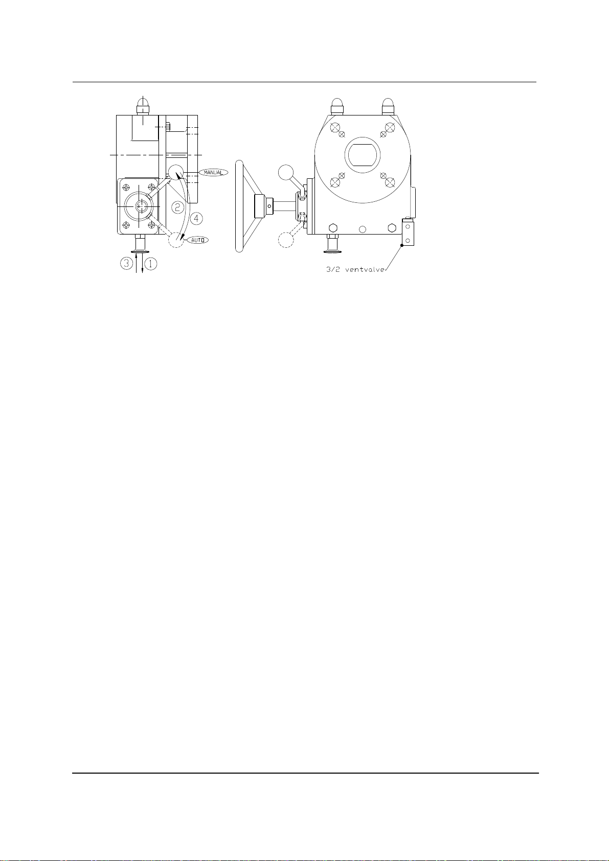
The ILG/D is a manual declutchable override quarter turn gearbox for double acting actuators.
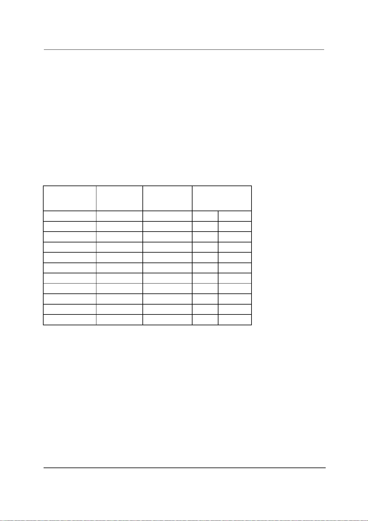
For connection data, maximum allowable input- and output torque refer to table 1.
This manual describes the installation of the gearbox and its parts. The intention of the ILG/D gearbox is to
operate the valve in case of a failing actuator system.
1. The gearbox is standard delivered in the closed position.
2. It is recommended to mount a handwheel on the insputshaft, before assembling the gearbox to the
valve.
3. Check if the boltcircle of the flanges (of gearbox and valve) coincide. Also check if the valvestem and
the bore at the bottom of the gearbox match.
4. Make sure the valve is in the closed position. If not, close the valve before continuing.
5. Check if the gearbox is in fully closed position by turning the handwheel clockwise.
6. In case of use of studbolts for fixing the gearbox to the valve, it is recommended to screw them into the
bottomflange of the gearbox before mounting the gearbox to the valve.
7. The use of a gasket between the flange of the valve and gearbox is recommended.
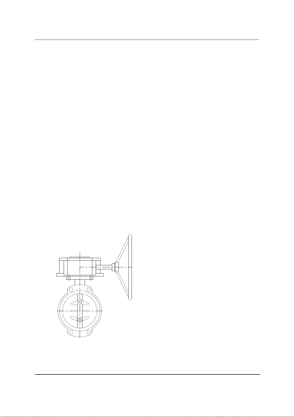
8. The gearbox is mounted perpendicular to the valve (see figure 1).
figure 1 : Gearbox perpendicular to the valve

Gearbox ILG/D manual
Rotork Gears bv
5
9. Fasten the gearbox to the valve with nut and ring. In case of use of bolts, for the maximum
tappingdepth, see table 2. For tightening, refer to standard VDI 2230.
PCD F05 F07 F10 F12 F14 F16 F25 F30 F35 F40
max. screw depth 8 11 13 16 18 18 18 18 30 36
table 2 : maximum tappingdepth per pitch center diameter
10. The 3/2-valve is optional and meant for gearbox mode detection. The 3/2 ventvalve is open (and vents
to atmosphere) with the gearbox in manual mode.
P
A
R
Figure 2 : port designation
11. The assembly is now ready for adjustment. (see chapter 3).
3. Adjustment of the stopscrews
The gearbox is mounted on top of the valve (see installation).
1. In case of a pneumatic actuator, be sure the actuator depressurised.
2. Put the gearbox in the manual-mode by turning the handle 90 degrees counter clockwise (see 'operating'
and/or figure 5: 1->2->3)
3. Turn the valve into fully closed position by turning the handwheel clockwise.
When the fully closed position can not be achieved, loosen the stopscrew-close (see figure 2). Continue
turning the handwheel until the valve is fully closed.
4. Turn the screw back into the gearbox until blocked (handtight). Secure the stopscrew–close with the
counternut.
Figure 3 : ILG/D gearbox stopscrew adjustment
5. Open the valve by turning the handwheel counter-clockwise. When the fully open position can not be

Gearbox ILG/D manual
Rotork Gears bv
6
achieved, loosen the stopscrew-open (see figure 3). Continue turning the handwheel until the valve is fully
open.
6. Turn the stop-screw back into the gearbox until blocked (handtight). Secure the stopscrew–open with the
counternut.
7. Close the valve completely with the handwheel.
8. Pull the knob outwards (1) and turn the handle (clockwise) until knob falls back into its locked-position
(3).
9. Adjustment completed. The gearbox is now ready for manual or automatic operation.
10. Prior to mounting an actuator,
a. adjust the stopscrews.
b. position the driveshaft (see figure 4) in top of the gearbox.
c. make sure the actuator is in closed position.
Figure 4 : Driveshaft example from an ILG/D gearbox
4. Operating
The ILG/D is a manual declutchable override quarter turn gearbox for double acting pneumatic or electric
actuators.
For maximum allowable input- and outputtorque, refer to table 1.
The gearbox is delivered in automatic mode: valve-operating by actuator.
1. The gearbox is manually operated by handwheel.
2. Prior to manual operation, the gearbox has to be put into manual mode. To achieve this, refer to figure 5
and follow the next points :
i. Pull the knob outwards (1). Secure the knob in this position.
ii. Turn the handle counter clockwise (2) and release the knob. Continue turning the handle until the knob
falls back into locking position (3).
NB When the handle can not be fully turned over ±90°, turn thehandwheel slightly. Continue turning the
handle until full engagement is achieved (knob returns to start position).
iii. The gearbox is ready for manual operation.

Gearbox ILG/D manual
Rotork Gears bv
7
Figure 5 : ILG/D gearbox
3. To close the valve, turn the handwheel clockwise.
4. Stop turning until the required valveposition is achieved. The number of turns needed from totally open to
totally close the valve is in table 3.
5. When the valve can not be totally opened (or closed), first the cause has to be detected and solved.
6. In case of malfunction of the gearbox, this one has to be replaced (see chapter installation for
dismounting). Return the gearbox to your supplier for repair.
7. When you do the repair in house, all replacement parts must be obtained from the manufacturer to assure
proper operation of the gearbox.
8. When the fault is repaired, turn the handwheel until blocked.
9. Declutch the gearbox:
i. Pull de knob outwards (1).
ii. Turn the handle clockwise (4) and release the knob. Continue turning the handle until the knob falls
into its locking position (3).
10. In case of opening the valve, follow procedure described under point 2 to 5. Except point 3: to open the
valve, turn the handwheel counter-clockwise.

Gearbox ILG/D manual
Rotork Gears bv
8
type gearbox
Number of
turns
ILG/D 100 10
ILG/D 200 8.75
ILG/D 600 11.5
ILG/D 900 10.75
ILG/D 1500 14.25
ILG/D 2400 17
ILG/D 5000 26
ILG/D 8000PR3 78
ILG/D 16000PR6 117
ILG/D 232-10 9.25
table 3 : number of turns to open / close.
5. Maintenance
Under normal conditions, the gearbox is maintenance free.
The Rotork Gears ILG/D gearboxes can be used at ambient temperatures from –20 to + 120°C. Other
temperature ranges are available on request.
The standard gearbox is sealed to IP65 (dust tight and water jet proof). Cleaning can be done with a water hose,
not a high pressure water jet. As an option ILG/D gearboxes can also be supplied sealed to IP67 or IP68.
This manual suits for next models
9
Table of contents
Other rotork Industrial Equipment manuals