ROTOSOL RITxK Series User manual

1
USER'S MANUAL
On-Grid PV Inverter
Series: RITxK(x=5,6,8,10,15,20,30,40,50,60)
USERS MANUAL

2
INSTALLATION,OPERATION AND REPAIR MANUAL
About Rotosol
Rotosol solar (Division of Rotomag Motors and Controls Pvt. Ltd., located Near Anand,Gujarat,India .,
which is specialized in manufacturing of solar PV inverters.
Rotosol is dedicated to providing perfect power conversion and control solutions for solar power generation
installations , manufacturing and marketing of solar PV inverters. Rotosol possesses the first-class
production equipment . Rotosol provide all kinds of high-quality and reliable grid-connected solar inverters
and energy system solutions to satisfy the consistently increasing demands for global energy.
The newly designed PV Inverter features itself with full load high efficiency, high reliability and user-friendly
interface. The maximum conversion efficiency of our inverter is up to 98%. A user-friendly installation &
interface, professional industrial design, and design for reliability mechanism, give the Inverter Family a
competitive edge for customers from all regions.
As a customer-oriented company, Rotosol is always trying to improve product and enhance customer
satisfaction. High quality with customer satisfaction is the Goal of Rotosol , not just in product quality control,
but also in quality of service and support. Rotosol is able to help customers reduce energy consumption and
carbon dioxide emissions by leading green solutions.

3
CONTENTS
1. About This manual............................................................................................................................................4
1.1Scope of Validity.................................................................................................................................. 4
1.2Target Group...........................................................................................................................................4
1.3Additional Information........................................................................................................................4
2Safety Instructions..................................................................................................................................................5
2.1 Safety Precautions..............................................................................................................................5
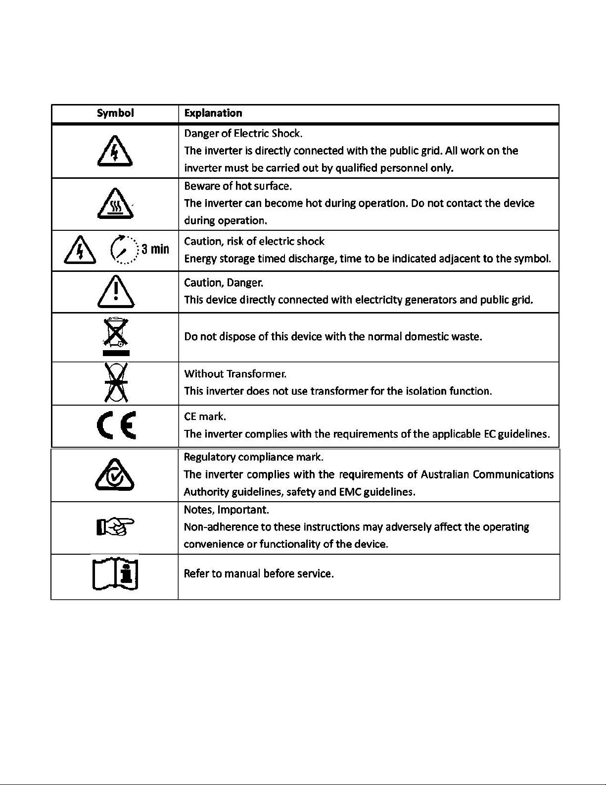
2.2 Explanations of Symbols................................................................................................................... 6
3 Unpacking...............................................................................................................................................................7
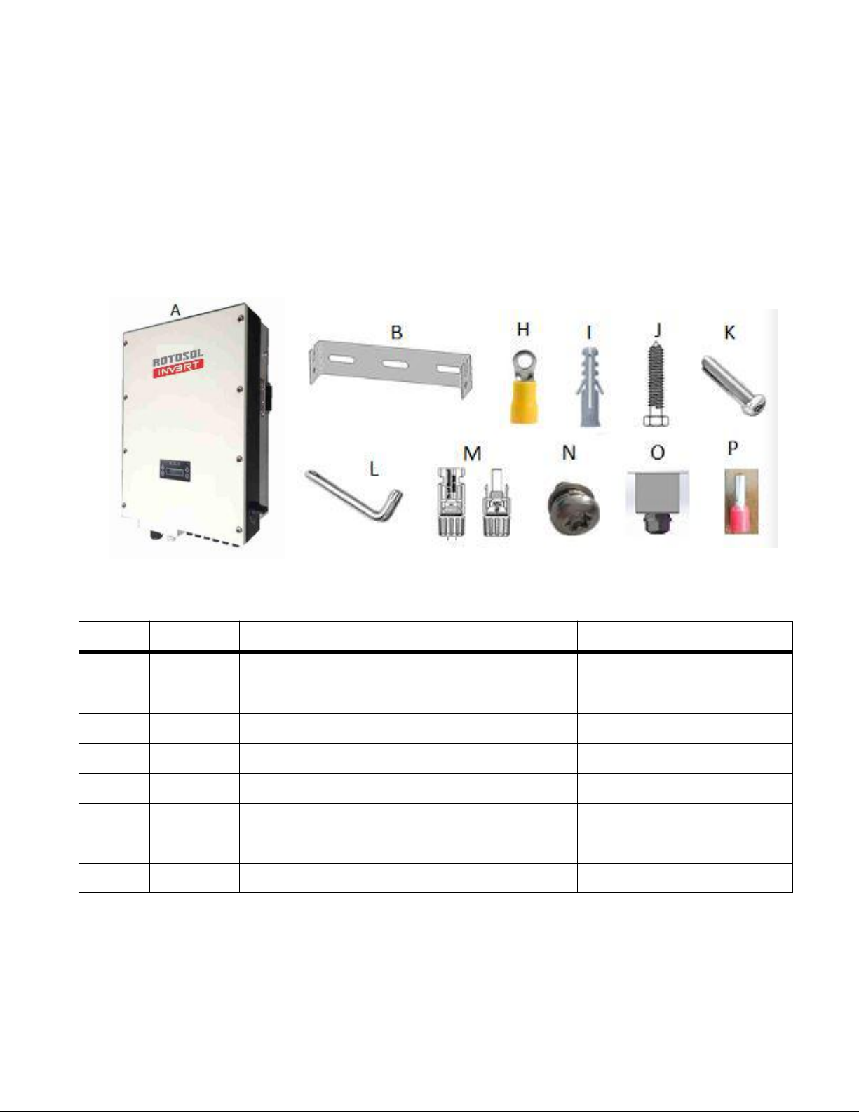
3.1 Assembly Parts...................................................................................................................................7
3.2 Identifying the Inverter...................................................................................................................... 8
4 Mounting..................................................................................................................................................................9
4.1 Safety................................................................................................................................................. 9
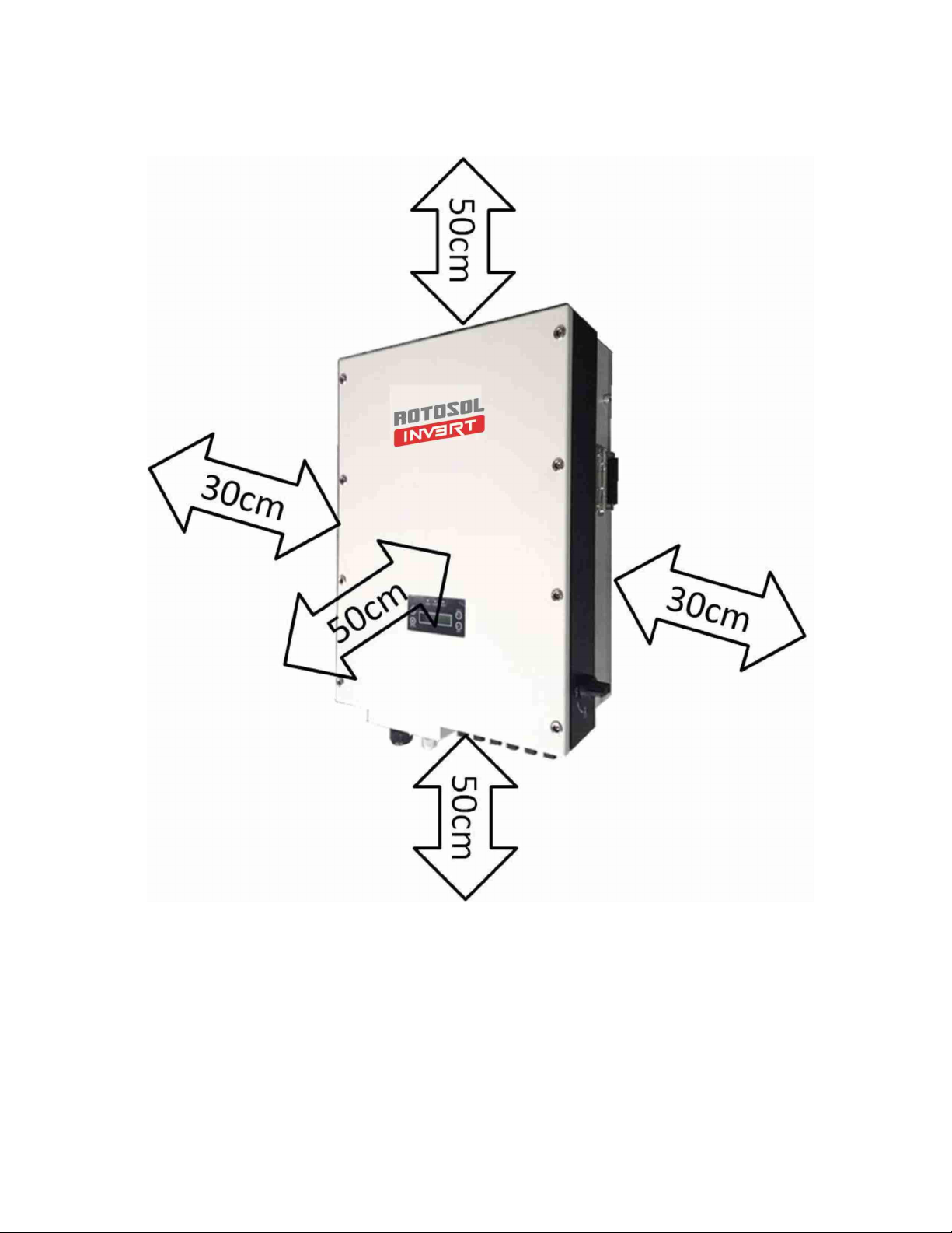
4.2 Selecting the Appropriate Mounting Location...................................................................................9
4.3 Mounting the Inverter with Wall Mounting Bracket........................................................................11
5 Electrical Connection.................................................................................................................................... 12
Notes:...........................................................................................................................................................................12
5.1 Overview of the Connection Area................................................................................................... 13
The following figures show the assignment of the individual connection areas on the bottom of
theInverter.............................................................................................................................................. 13
5.2 Connection to the Public Grid (AC)................................................................................................ 13
5.3 Connection to the PV Generator (DC).............................................................................................16
6 System Diagram............................................................................................................................................... 21
7 Operation..............................................................................................................................................................23
7.1 Overview of Control and Displays........................................................................................................ 23
7.2Commissioning.................................................................................................................................... 24
7.3 LED Display........................................................................................................................................ 24
7.4 LCDDisplay........................................................................................................................................25
8 Trouble Shooting.................................................................................................................................................30
9 Inverter Inspection and Repair.................................................................................................................34
9.1 LCDcannotDisplay..............................................................................................................................34
9.2 LCDdisplay FaultCodes....................................................................................................................... 34
9.3 Repeat Countdown,cannot generation......................................................................................................35
9.4AC circuit breaker trip............................................................................................................................ 35
9.5 Monitoring Fault................................................................................................................................... 35
9.6 ProblemDuring InverterGeneration.........................................................................................................35
9.7 Power Components Inspection(without DC power supply)......................................................................36
9.8 MOSFET Driver Inspection(for 5th generation models)..........................................................................41
9.9 Inverter Frequently Tripping Due to Grid Fluctuation..............................................................................41
10 Contact............................................................................................................................................................... 43
Annex Warranty Terms (Overseas)............................................................................................................ 43

4
1. About This manual
1.1 Scope of Validity
This manual describes the installation, commissioning, operation and maintenance of the following on-grid
PV inverters produced by Rotosol:
Commercial Systems & Power Plants 5-60KW
RIT5K , RIT6K, RIT8K, RIT10K, RIT15K, RIT20K, RIT30K, RIT40K, RIT50K, RIT60K
Please keep this manual all time available in case of emergency.
1.2 Target Group
This manual is for qualified personnel. The tasks described in this manual must only be performed by
qualified personnel.
1.3 Additional Information
For more information please go through the website www.rotosol.solar

5
2 Safety Instructions
2.1 Safety Precautions
1. All work on the inverter must be carried out by qualified electricians and ensure that children can
not access to the equipment.
2. The device may only be operated with PV generators. Do not connect any other sources of energy
to the device.
3. This PV generator and inverter must be connected to the ground in order to reach maximum
protection for property and persons.
4. Do not touch cover until 3 minutes after disconnecting all sources of supply. This is because the
charge stored in capacitors may result a risk of electric shock.
5. The enclosure of Inverter can become hot during operation. To reduce the risk of injury, do not
touch the cover, heat sink at the back of the PV-lnverter or nearby surfaces while Inverter is
operating.
6. Do not use the equipment for purposes other than those described in this manual.
7. Both the inverter and associated transport packaging are mainly made of recyclable raw materials.
Please ensure that the used device and any relevant accessories are disposed of in accordance
with applicable regulations.
8. Packed with damping EPE and carton, Rotosol inverter should be placed upwards and handled with
care in delivery. Pay attention to waterproof.
9. Alternative uses, modifications to the inverter not recommended by Rotosol or the installation of
components not sold by Rotosol void the warranty claims.

6
2.2 Explanations of Symbols

7
3 Unpacking
3.1 Assembly Parts
Please check the delivery for completeness and any visible external damage. Contact your dealer at once
if anything is damaged or missing.
Assembly parts are as listed below:
Object
Quantity
Description
Object
Quantity
Description
A
1
Solar inverter
B
1
Wall mounting bracket
C
1
User manual
D
1
Certificate of inspection
E
1
Installation diagram
F
1
Notice for installation
G
1
Warranty card
H
1
RV5.5-6 terminal
I
3
Plastic Expansion Tube
J
3
Tapping screw
K
1
Security screw
L
1
Screwdriver for security screw
M
2sets
DC plug connector
N
4
Screw
O
1
Waterproof Junction Box
P
4
Terminal

8
3.2 Identifying the Inverter
You can identify the inverter by the type label. Information such as serial number (Serial No.) and
model name of the inverter, as well as the device's technical parameters are specified on the type label.
The type label is on the right side of the enclosure.

9
4 Mounting
4.1 Safety
DANGER!
Danger to life due to potential fire or electric shock.
Do not install the inverter near any inflammable or explosive items. The inverter will be directly connected
with high voltage power generation device. The installation must be performed by qualified personnel only
in compliance with national or local standards and regulations.
CAUTION!
Danger of burn injuries due to hot enclosure parts.
•Install the inverter so that it cannot be touched inadvertently.
Risk of injury due to the heavy weight of the inverter.
•Take the inverter's weight into account for mounting. (Weight of inverter refers to chapter 8.)
4.2 Selecting the Appropriate Mounting Location
Consider the following points when selecting where to install:
The mounting method and location must be suitable for the inverter's weight and dimensions.
The inverter must be installed in the solid walls ,such as brick walls or concrete walls in case of
vibration noise or inverter falling off.
The installation site should be clearly visible and can be safely into without aids such as scaffold.
For the convenience of checking the LCD display and possible maintenance activities, please
install the inverter at eye level.
The altitude of installation site should be below 2000m,more than 2000m above the sea level will
cause derating.
The ambient temperature of installation site should be between -20 °C and +55 °C (between -4 °F
and 131 °F).
Install the inverter directly exposing to strong sunshine is not recommended, the excess heating

10
might lead to power reduction.
Leave enough effective space around the inverter for better ventilation.
• Vertical installation, wiring area must be downside, lateral installation is not allowed; in backward
tilted installation, tilt angle should not exceed 30 degrees; Forward tilted, horizontal or inverted
installation is not allowed.

11
4.3 Mounting the Inverter with Wall Mounting Bracket
1. Use the wall mounting bracket mark the drilling position and drill the holes for the screws.
2.Fix the wall mounting bracket with the equipped self-tapping screw.
3. Hang the inverter to the mounting bracket and ensure the slot is fitted on the bracket.
4. Check to ensure the inverter is correctly seated. Make sure to lock it with the security
screws. (See the figure below.)

12
5 Electrical Connection
Notes:
1. Electrical installation & maintenance shall be conducted by licensed electrician and shall comply
with local Wiring Rules.
2. After the inverter has been installed in its fixed position, the electrical connection to the unit can be
established.
3. Make sure Max. Open Voltage and short-circuit current of the each PV strings accord with the Spec.
4. Choose the appropriate cable width for AC/DC wire. The cross sectional area of DC input conductor
lead should be 4mm2PV wire, that of AC output conductor should also be 4mm2cooper wire, and
that of external ground conductor should be 4mm2cooper wire.
5. On both sides of inverter to the grid and PV array, there must be between circuit breaker and surge
protector, and during inverter electrical connections, circuit breakers on both sides should be
disconnected to prevent electric shock.
6. To connect the inverter,the AC and DC sides must be disconneted from all power sources and
secured against being inadvertently swithced back on.
7. Before connecting the inverter to PV arrays and public grid, make sure the polarity is correct.

13
5.1 Overview of the Connection Area
The following figures show the assignment of the individual connection areas on the bottom of theInverter.
Object
Description
a
DC connectors ( + ) for connecting the PV strings
b
DC connectors ( − ) for connecting the PV strings
c
WiFi/RS485 Communication Waterproof Connector
d
Waterproof Junction Box, AC connection
e
DC Switch
5.2 Connection to the Public Grid (AC)
5.2.1 Conditions for Connection
CAUTION!
Unit Disconnection From Load
Disconnect the circuit breakers and switches of inverters AC and DC sides.
5.2.2 Connection to Public Grid (AC)

14
Measure the grid voltage to make sure within the permissible range. Disconnect the circuit
breaker between the inverter and the grid.
1. Disconnect the DC and AC breaker, DC switch in the"OFF"state..
2.Disconnect the DC and AC breaker, DC switch in the"OFF"state.
3. Assembly yellow-green Ground wire RV5.5-6 terminal, and connect to one ground terminal.

15
4.Prepare AC cable(Φ4mm2 or bigger), stripping length is 14±0.5mm. Connect the cable with
terminals.
5. Run the cable harness with the pressed terminals through the junction box and insert the black
cable harness, L1, L2 and L3 into the caps of N, W, V and U as shown in the system connection
diagram. Tighten the screws.

16
6. Close junction box and tight the screws
5.3 Connection to the PV Generator (DC)
CAUTION!
Unit Disconnection From Load
Disconnect circuit breakers and switches on both AC and DC sides
5.3.1 Conditions for the DC Connection
The connected PV modules must meet following requirements
-Same type
-Same model
-Identical alignment
- Identical tilt
The following limit values at the DC input of the inverter must not be exceeded (connecting to a higher

17
voltage will destroy the device):
Type
Maximum input voltage [Vd.c]
Maximum input current [Ad.c]
RIT5K
1000
11x2
RIT6K
1000
11x2
RIT8K
1000
11x2
RIT10K
1000
11x2
RIT15K
1000
22+11
RIT20K
1000
22x2
RIT30K
1000
33x2
RIT40K
1000
40x2
RIT50K
1000
36x3
RIT60K
1000
40x3
5.3.2 Assembling the DC Plug Connector
In order to connect to the inverter, all connection cables of the PV modules must be equipped with the DC
plug connectors provided. You will find the necessary DC plug connector for DC connection in the package.
To assemble the DC plug connectors, proceed as detailed below. Ensure the plug connectors have the
correct polarity.
The plug connector in DC side includes male and female as blow.
Please note that the sizes of metal connecting tubes are different. The bigger one is for female connector
and the smaller one is for male connector.

18
Assembly Instructions:
♦Prepare the DC wire to connect the positive and negative DC arrays. Stripping length is 12~15mm,
sectional area is 4 mm2as below.
♦ Insert the DC wire to metal connecting tube. Make sure all line heads are in the connecting tube as
picture blow.
♦ Use crimping pliers to fasten the metal connecting tube and copper wire. Make sure the harness will not

19
fall off, see picture below.
♦ Insert the assembled cable into male/female connector. A "chick" sound can be heard when
connecting correctly. Then tighten the cap. Refer to the picture below.
5.3.3 Connecting the PV Generator (DC)
DANGER!
Danger to life due to high voltage in the inverter.
• Before connecting the PV generator, ensure that the AC&DC circuit breaker is switched off.
Notes:
1. Make sure that you have disconnected circuit breakers and switches on both DC and AC sides.
2. Check the connection cables of the PV modules for correct polarity and that the maximum input
voltage of the inverter is not exceeded.
3. Check the DC plug connector for correct polarity and well connected.

20
Plug the DC plug connectors into DC terminals on Inverter.
The inverter DC input is equipped with two groups(DC-A and DC-B) of connecting sockets for DC input ,
and each group contains two pairs of connecting sockets (DC+ and DC-). Make sure at least one pair of
DC terminal in each group is connected with PV array in installation,and group A and B must be
connected with two arrays separately but not with one array,see picture below.
This manual suits for next models
10
Table of contents
Other ROTOSOL Inverter manuals
Popular Inverter manuals by other brands

YASKAWA
YASKAWA SOLECTRIA XGI 1500-DCG Series Installation and operation guide

Strongway
Strongway 53069 owner's manual

Agilent Technologies
Agilent Technologies AGILENT U2761A user guide

TEC
TEC TECDrive20-EU Series Operation manual

Clenergy
Clenergy PV-ezRack SolarRoof Isolator Shade installation guide

Renogy
Renogy PGH1-10111S manual