© Rototilt Group AB 2018-06-28
!
PULSATING
LIGHT
FIXED
LIGHT
TCU
CCU
Sound
Light
Power
CAN-bus
Internal
Error
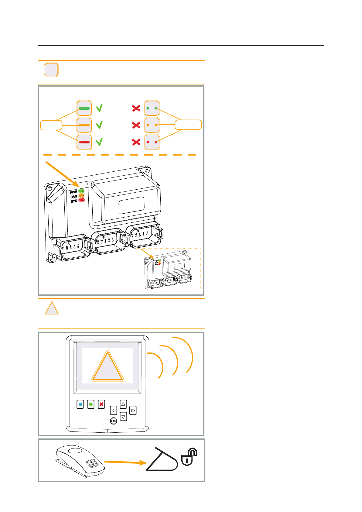
LED INDICATIONS
OK Error
EN English
Control unit
The control units have three LEDs:
green, orange and red. When the system
is working correctly, all LEDs light and
with no ashing.
When a malfunction occurs the relevant
LED begins ashing.
PWR (green) shows whether the unit is
powered up.
CAN (orange) shows whether
communications with CAN bus are
working.
SYS (red) shows whether the unit’s
internal components are working
correctly.
The control units are not interchangeable.
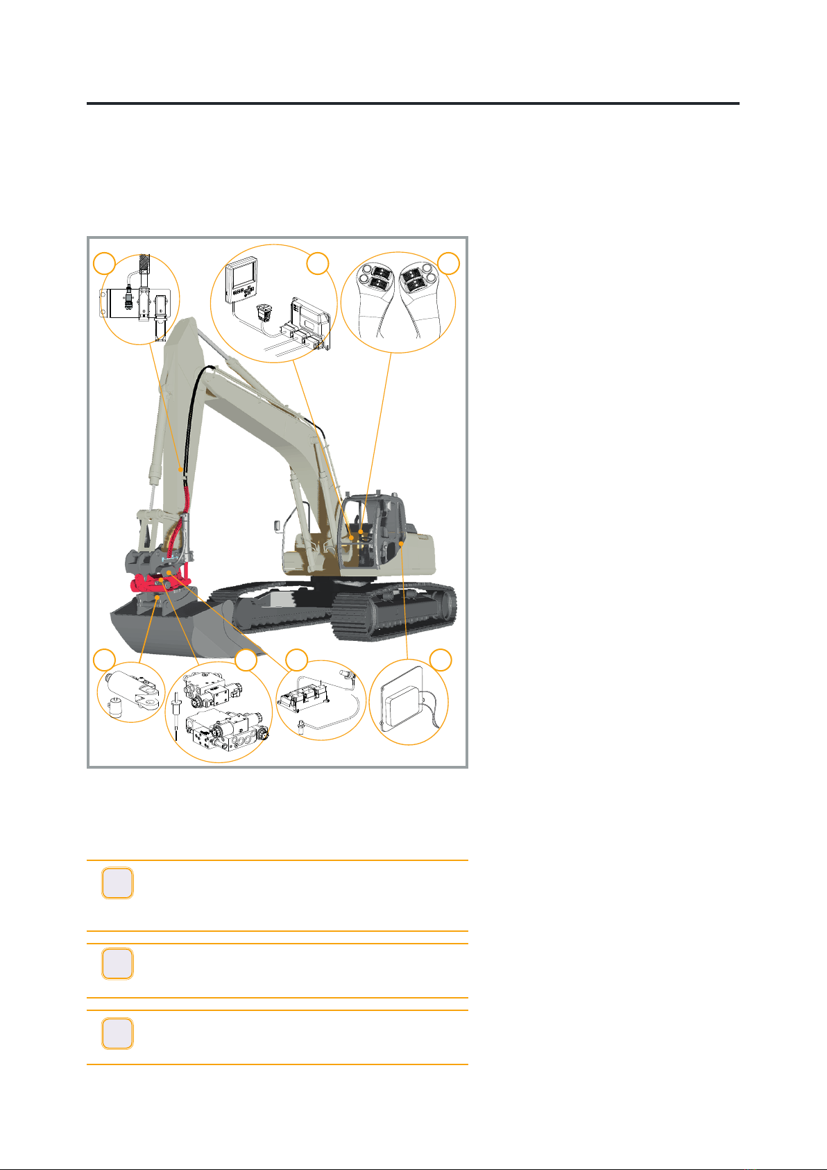
Cab control unit, CCU
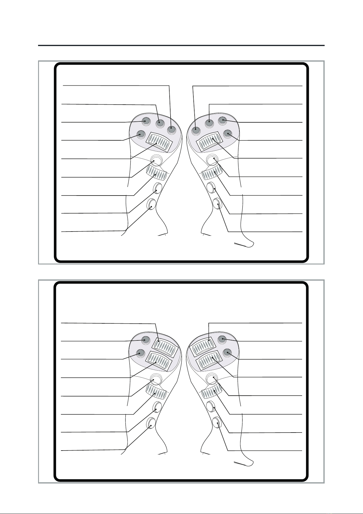
The control unit receives signals from the
handles and switches.
The control unit sends signals to the
valve block shunt and tiltrotator via CAN
bus.
Rototilt® control unit, TCU
The control unit receives signals from
the cab control unit, and from sensors in
Rototilt®.
Rototilt® control unit sends signals to
valves and LED lamp.
There is a sensor in the Rototilt® control
unit that detects the tilt angle.
!
IMPORTANT - The control units have a similar
appearance but the content differs. They are not
interchangeable.
Display
Settings, calibration and activation of
certain functions are made via the display
and its keys.
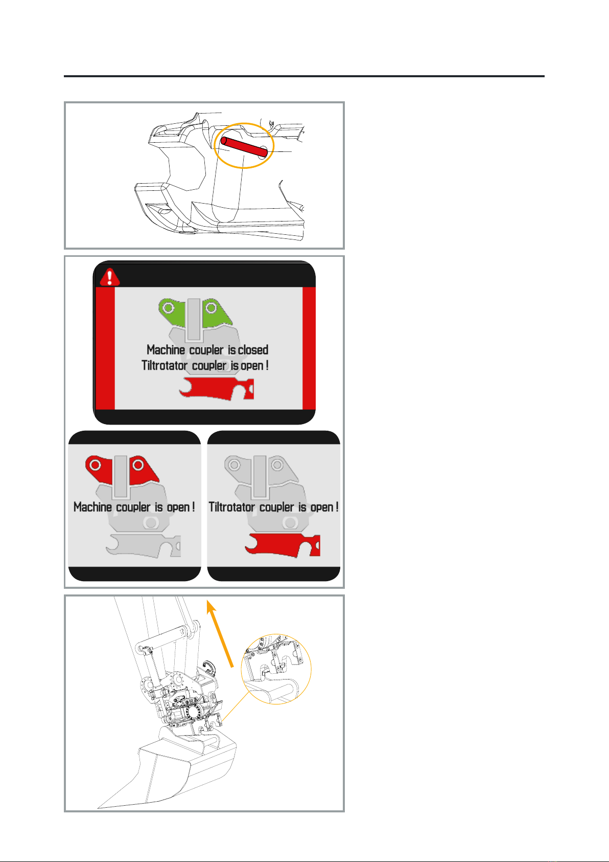
There is a buzzer in the display that
sounds to attract the operator’s attention
if the quick coupler locking function is
open or in the event of a fault.
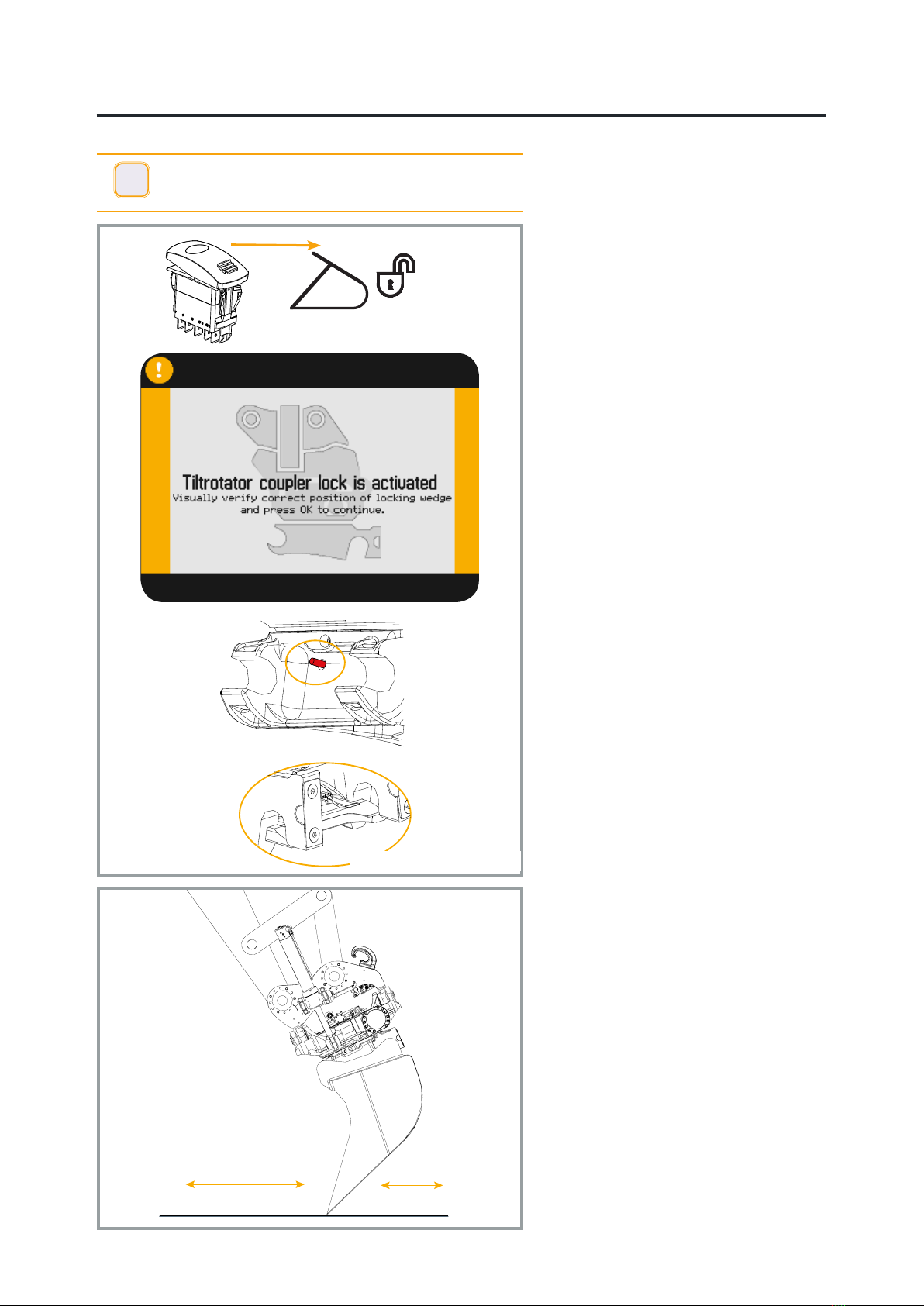
Switch, quick coupler locking
function
The quick coupler locking function switch
is interlocked. This prevents accidental
activation of the quick coupler locking
function.
!
WARNING! A problem has occurred if the buzzer
sounds without activating the quick coupler locking
function switch. The display shows information
about the current problem.