ROTOTILT ICS Direct Operating and installation instructions

2019-08-19
_7733
2200399
Control System - ICS Direct
Track Control
Translation of the Original Instructions _EN

© Rototilt Group AB 2019-08-19
1 2
3
4 5
English
EN
Overview
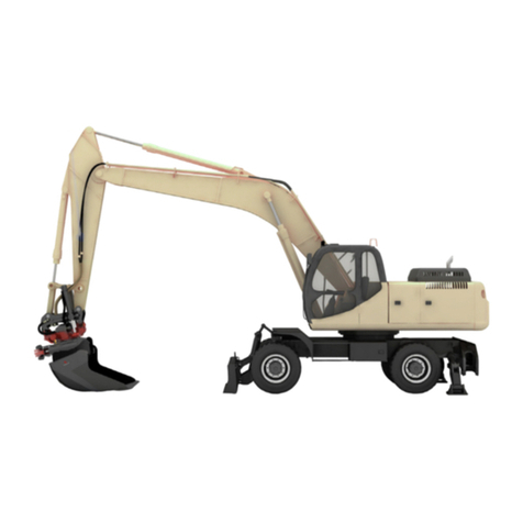
The product described in the document consists of components for the ICS Direct track control system.
The overviews show standard equipment and options.
Refer to the illustrations and lists below and on the following pages.
ICS Direct is design to facilitate the movement of the base machine/excavator when working. ICS Direct
track control is manoeuvred using switches and or rollers in the handles. In most cases this permits the
operator to work in a more ergonomic position.
Control system of the
ICS Direct type
A base machine/excavator equipped with
ICS Direct track control has the following
components installed:
1. Indicator lamp
Decal - track control
2. Handles with controls to operate the
base machine/excavator, ordered
separately
3. Display - included in the control
system ICS, ordered separately
4. Valve block - Track control
5. Control unit
Buzzer
!
IMPORTANT - Read through the instructions for the
control system, tiltrotator and base machine/excavator use
before starting work. Pay particular attention to the safety
instructions.
!
IMPORTANT - If you suspect alternative control if
malfunctioning, always use the base machine/excavator’s
controls.
2200399_ _7733

© Rototilt Group AB 2019-08-19
IN G¼" OUT G¼"
IN G¼" OUT G¼" IN G¼" OUT G¼"
IN G¼" OUT G¼"
P G¼"
P G¼" T G¼"
T G¼"
2
5 7
84
1 3
6
Alternative
steering
inactive
ICS Direct
activated
ICS Direct
installed
English
EN
Control unit
The control unit has two diodes and is
connected to a buzzer.
The buzzer sounds in the event of a
system error and twice during start-up.
When the system works correctly, the
green diode lights with a xed light and
the buzzer is silent.
When a system malfunction occurs the
LEDs light and the buzzer sounds in
various combinations.
See Trouble shooting ICS Direct
The control unit can be connected to a
PC for reprogramming, calibration and
detailed trouble shooting.
Valve block, track control
The valve block for track control is
usually installed below the cab oor of
the base machine/excavator.
The valve block is connected in parallel
to the base machine/excavator’s control
of the hydraulic ow.
The operator controls the operation and
steering of the base machine/excavator
via the rollers and/or switches tted in the
handles.
Alternative operation is only active when
the base machine/excavator’s control
inhibitor is deactivated.
Lamp and decal
A lamp and decal are installed on the
right-hand console. The decal shows
alternative control is installed on the base
machine/excavator.
When ICS Direct is activated the lamp
lights.
When the operation inhibitor is activated
the lamp ashes to warn that the system
is switched off.
2200399_ _7733

© Rototilt Group AB 2019-08-19
S3
R3
Left Handle
Right Handle
R3
English
EN
!
IMPORTANT - The base machine/excavator’s factory
mounted handles have been replaced with handles
adapted for ICS Direct.
Carefully check the changed functions, for both the base
machine/excavator and alternative control.
Handles
The handles are equipped with switches
and rollers to control the functions on
the base machine/excavator and for
alternative control.
The rollers in the handles must have
proportional control.
The handle functions are congured by
an authorised installer.
One of several possible examples of
connection to the alternative control is
described below.
Left Handle
S3 Activate alternative control
R3 Steering
Right = Turn right
Left = Turn left
Right Handle
R3 Drive
Right = Drive forwards
Left = Drive backwards
Information about functions
Information concerning the handles’
current conguration is available in three
places: On the decal, on the display and
in the instructions for the base machine/
excavator.
Display
The symbol on the display comes on
when alternative operation is activated.
2200399_ _7733

© Rototilt Group AB 2019-08-19
Inactivate
4
Activate
Sound
1
2
3
Shut off
Lever
Light
Warning Flashing light
Sound 3 sec.
5
English
EN
Operation
Activate alternative control
1. The operation inhibitor must be
deactivated, (usually occurs in the
horizontal position). Switch the base
machine/excavator to work mode.
2. Activate alternative control with the
connected switch in the handle.
3. The control system’s indicator lamp
lights to indicate that alternative
control is activated.
The alternative control symbol on the
display is shown.
Deactivate
ICS Direct is deactivated as follows:
4. Switch off alternative control with the
switch in the handle.
The control system’s indicator lamp
goes out to indicate that alternative
control is deactivated.
The symbol is not shown on the display.
or
5. Activate the operation inhibitor.
The control system’s indicator lamp
ashes and the buzzer sounds for
3 seconds to warn that the system is
switched off.
!
IMPORTANT - If you suspect alternative control if
malfunctioning, always use the base machine/excavator’s
controls.
i
INFO - If the voltage to the base machine/excavator fails,
the operation inhibitor must be activated and deactivated,
as a function control.
i
INFO - Systems without an electric operation inhibitor
must be switched off using the activation switch.
Malfunctioning
When an error code is generated from a
function, all functions are blocked.
Once the error code has been identied
in the trouble shooting table, the buzzer
can be temporarily switched off.
The buzzer stops if the activation switch
is pressed and held for 3 seconds.
Restarting activates the buzzer again.
Alternative connection
The operation inhibitor must be
deactivated so that the system has the
requisite servo pressure. Also applies if
ICS Direct is not connected to the inhibitor.
Activate and deactivate with the switch in
the handle.
2200399_ _7733

© Rototilt Group AB 2019-08-19
1
1
2
2
A
A
B
B
1
2
A+2
A
A
B
2
Säkerhetsfunktion / Safety function
1
2
A+2
A
A
B
A
1
2
A+2 A
A
B
2
Rotation - Sväng - Framåt /
Rotation - Turn - Forward
Framåt - Sväng - Framåt /
Forward - Turn - Forward
Moturs / Counter Clockwise
Medurs / Clockwise
Framåt / Forward
Bakåt / Reverse
English
EN
Forward / Reverse
The operator moves the machine in a
straight line, either backward or forward,
using the roller on the right handle. The
speed is determined by the amount the
roller is moved (proportional control).
The output signal from the handle is routed
to the valve block (ICS Direct), which in
turn activates the hydraulic motors of both
tracks to move them at the same speed
and in the same direction.
Clockwise / Anticlockwise
The operator rotates the machine on the
spot, in either a clockwise or anticlockwise
direction, using the roller on the left handle.
The speed is determined by the amount the
roller is moved.
The output signal from the handle is routed
to the valve block (ICS Direct), which in
turn activates the hydraulic motors of both
tracks to move them at the same speed but
in opposite directions.
Left / Right turn
The operator moves the machine using a
combination of drive and steering, using
the rollers on both handles.
The operator can start rotating the machine
on the spot and then transition this into
a turning motion by activating the drive
roller. Steering can be started, ended and
resumed throughout the time the drive
roller is activated. Turning motions are
achieved by braking the hydraulic motor of
one of the tracks.
!
IMPORTANT – Incorrect connection results in,
among other things:
The safety function being overridden, as it is not
connected to the correct roller.
Auto-calibration of the system being deactivated.
Troubleshooting being impeded.
Safety function
The control for drive (forward/reverse)
has priority over the control for steering
(left/right).
If the control for drive is released while
steering in either direction, steering will
also stop.
The rollers must be returned to the neutral
position (incl. ramp time 0-1 sec.) before
steering can be resumed.
This safety function prevents the base
machine from performing any uncontrolled
lurching movements.
Without the safety function, the hydraulic
motors transition from the combination of
driving one track and braking the other to
driving both tracks in the opposite direction.
Using alternative control
2200399_ _7733

© Rototilt Group AB 2019-08-16
trouble:1 English
EN
EN -
Troubleshooting ICS Direct
Fundamental signal
combinations
The control unit has two diodes and a buzzer, which indicate how the control system is working.
The components light and sound at different intervals and combinations.
The components are controlled by the signals that pass between the control unit and the other parts of the
control system.
Correct function - When the green LED
lights with a xed light the control system
works correctly.
System inactive - When the green and
red LEDs light with a xed light the drive
mode switch is not activated.
Calibration - When the green and red
LEDs ash quickly and the buzzer sounds
the rollers are not calibrated correctly.
Input signal - When the green and red
LEDs ash slowly and the buzzer sounds
the input signal does not work correctly.
Output signal - When the green LED
ashes and the Red LED lights with a
xed light and the buzzer sounds the
output signal does not work correctly.
Detailed troubleshooting
Calibration
Red LED Green LED Buzzer Possible cause Action
Flashes
quickly.
1 ash Sounds
at the
same
rate as
the red
LED.
Roller left not calibrated. The
control system clears the roller’s
calibration and stops output
signals.
Cable breakage, connector play
or roller fault.
• Calibrate the roller by pulling it to each
end position for at least 3 seconds.
• Change the roller and perform the
calibration as set out above.
• Contact the service workshop.
Flashes
quickly.
2 ashes Sounds
at the
same
rate as
the red
LED.
Roller right not calibrated. The
control system clears the roller’s
calibration and stops output
signals.
Cable breakage, connector play
or roller fault.
Red LED Green LED Buzzer Possible cause Action
Extin-
guished
Fixed light Silent System works. None
Correct function
Red LED Green LED Buzzer Possible cause Action
Fixed light Fixed light Silent System inactive. Activate the system
System inactive.
2200399_ _7733

© Rototilt Group AB 2019-08-16
trouble:2 English
EN
EN -
Input signal
Red LED Green LED Buzzer Possible cause Action
Flashes
slowly.
1 ash Sounds
at the
same
rate as
the green
LED.
The supply to roller left broken,
caused by an open or short
circuit on the harness.
• Check the harness to the joystick in
terms of crush damage or open circuit.
• Restart the system.
• Contact the service workshop.
Flashes
slowly.
2 ashes Sounds
at the
same
rate as
the green
LED.
Roller left activated during start-
up of the control system. The
rollers’ output signal and the
output signal to the proportional
valve is blocked by the system.
• Return the roller to its zero position.
• Check that none of the rollers are
mechanically blocked.
• Check the condition of the rollers.
• Restart the system.
• Contact the service workshop.
Flashes
slowly.
3 ashes Sounds
at the
same
rate as
the green
LED.
The supply to roller right
broken, caused by an open or
short circuit on the harness.
• Check the harness to the joystick in
terms of crush damage or open circuit.
• Restart the system.
• Contact the service workshop.
Flashes
slowly.
4 ashes Sounds
at the
same
rate as
the green
LED.
Roller right activated during
start-up of the control system.
The rollers’ output signal
and the output signal to the
proportional valve is blocked by
the system.
• Return the roller to its zero position.
• Check that none of the rollers are
mechanically blocked.
• Check the condition of the rollers.
• Restart the system.
• Contact the service workshop.
Flashes
slowly.
5 ashes Sounds
at the
same
rate as
the green
LED.
Deviations in signal state on full
deection of roller left.
Error from the roller’s output
signals discovered by the
system after 0.2 seconds.
In the event of deviations,
the system blocks the roller’s
output signal and the output
signal to the proportional valve.
• Check the condition of the harness and
rollers.
• The fault lasts less than two
seconds:Return the roller to its zero
position.
• The fault lasts longer than two seconds:
Return the roller to its zero position.
Restart the control system.
Contact the service workshop.
Flashes
slowly.
6 ashes Sounds
at the
same
rate as
the green
LED.
Deviations in signal state on full
deection of roller right.
Error from the roller’s output
signals discovered by the
system after 0.2 seconds.
In the event of deviations,
the system blocks the roller’s
output signal and the output
signal to the proportional valve.
• Check the condition of the harness and
rollers.
• The fault lasts less than two
seconds:Return the roller to its zero
position.
• The fault lasts longer than two seconds:
Return the roller to its zero position.
Restart the control system.Contact the
service workshop.
Flashes
slowly.
7 ashes Sounds
at the
same
rate as
the green
LED.
Left roller activated during start-
up of the system.
• Return the roller to its zero position.
• Contact the service workshop.
Flashes
slowly.
8 ashes Sounds
at the
same
rate as
the green
LED.
Input signal fault from the
pressure sensor.
• Check the harness in terms of crush
damage or open circuit.
• Check the sensor
• Contact the service workshop.
2200399_ _7733

© Rototilt Group AB 2019-08-16
trouble:3 English
EN
EN -
Output signal
Red LED Green LED Buzzer Possible cause Action
Fixed light 1 ash Sounds
at the
same
rate as
the green
LED.
Functional fault on output
signal wire 1.
Output signal blocked.
• Check the harness in terms of crush
damage or open circuit.
• Check the condition of the valve.
• Return the roller to the zero position.
• Contact the service workshop.
To reset the fault indication, restart the
system by disconnecting the voltage on the
base machine.
Fixed light 2 ashes Sounds
at the
same
rate as
the green
LED.
Functional fault on output
signal wire 2.
Output signal blocked.
• Check the harness in terms of crush
damage or open circuit.
• Check the condition of the valve.
• Return the roller to the zero position.
• Contact the service workshop.
To reset the fault indication, restart the
system by disconnecting the voltage on the
base machine.
Fixed light 3 ashes Sounds
at the
same
rate as
the green
LED.
Functional fault on output
signal wire 3.
Output signal blocked.
• Check the harness in terms of crush
damage or open circuit.
• Check the condition of the valve.
• Return the roller to the zero position.
• Contact the service workshop.
To reset the fault indication, restart the
system by disconnecting the voltage on the
base machine.
Fixed light 4 ashes Sounds
at the
same
rate as
the green
LED.
Functional fault on output
signal wire 4.
Output signal blocked.
• Check the harness in terms of crush
damage or open circuit.
• Check the condition of the valve.
• Return the roller to the zero position.
• Contact the service workshop.
To reset the fault indication, restart the
system by disconnecting the voltage on the
base machine.
Fixed light 5 ashes Sounds
at the
same
rate as
the green
LED.
Start-up check that indicates
whether one of the valves is
not connected to the control
system.
• Check the harness in terms of crush
damage or open circuit.
• Check the condition of the valves.
• Restart the control system.
• Contact the service workshop.
To reset the fault indication, restart the
system by disconnecting the voltage on the
base machine.
Fixed light 6 ashes Sounds
at the
same
rate as
the green
LED.
Functional fault on output signal
wire Auxiliary.
Output signal blocked.
• Check the harness in terms of crush
damage or open circuit.
• Check the condition of the valves.
• Restart the control system.
• Contact the service workshop.
To reset the fault indication, restart the
system by disconnecting the voltage on the
base machine.
2200399_ _7733

© Rototilt Group AB 2019-08-19
schema:1
IN G¼" OUT G¼"
IN G¼" OUT G¼" IN G¼" OUT G¼"
IN G¼" OUT G¼"
P G¼"
P G¼" T G¼"
T G¼"
2
5 7
84
1 3
6
Schematics and Overwievs for hydraulic as well as electrical systems, in the following pages are meant to
serve mainly as a guide for Troubleshooting.
!
WARNING!
More extensive adjustments and repairs must be done by
an authorized service workshop.
Schematics
Valveblock, Track Control
ICS Direct Track Control can be adapted
with two alternative options for Valve
Block. Both Valve Blocks are connected
to the same functions for the system.
Illustration below shows the the Valve
Block in general use.
English
EN
EN -
2200399_ _7733

© Rototilt Group AB 2019-08-19
schema:2
IN IN
OUT
All Adapters = G¼"
T
P
WP1
IN
OUT
OUT
WP2
IN
OUT
T
P
WP3
Valveblock, Track Control
ICS Direct Track Control can be
adapted with two alternative options
for Valve Block. Both Valve Blocks are
connected to the same functions for the
system. Illustration below shows the
the Valve Block applicable for certain
machineadapted systems.
English
EN
EN -
2200399_ _7733

© Rototilt Group AB 2019-08-19
schema:3
Harness ICS Direct
Harness ICS Direct General version
English
EN
EN -
2200399_ _7733

© Rototilt Group AB 2019-08-19
schema:4
Hose connections basemachine
original valve for tracksteering
ADAPTER
HOSE
LEFT
TRACK
RIGHT
TRACK
MAIN VALVE BLOCK -
BASE MACHINE
Reverse
Forward
Reverse
Forward
LEFT
TRACK
RIGHT
TRACK
ORIGINAL VALVE
PEDAL
Reverse
Forward
Reverse
Forward
P
T
Hose connections Valve Block ICS Direct
LEFT
TRACK
RIGHT
TRACK
MAIN VALVE BLOCK -
BASE MACHINE
Reverse
Forward
Reverse
Forward
LEFT
TRACK
RIGHT
TRACK
ORIGINAL VALVE
PEDAL
Reverse
Forward
Reverse
Forward
P
T
LEFT RIGHT
ICS Direct
ReverseForward Reverse Forward
P
TOUT 1
IN 1
OUT 2
IN 2
OUT 3
IN 3
OUT 4
IN 4
Hose connections ICS Direct
English
EN
EN -
2200399_ _7733
Other manuals for ICS Direct
1
Table of contents
Other ROTOTILT Control System manuals