Rotrex C15-16 Release Note

WWW.ROTREX.COM

Technical Handbook
Rev. 1.6
WWW.ROTREX.COM Page 1 of 41
Index
INTRODUCTION 3
1. THE IDEAL APPLICATION DEVELOPMENT CYCLE 4
2. ROTREX TECHNOLOGY BASICS 6
2.1 System overview 6
2.2 Supercharger internal structure 7
2.3 Traction drive principles and key benefits 8
3. CHOOSING THE RIGHT ROTREX 9
3.1 General guidelines 9
3.2 Supercharger selection example: boosting 105hp to 150hp 10
4. DESIGNING AND HANDLING INTERFACES 11
4.1 Pulleys and other drive types 11
4.2 Belt drives 12
4.2.1 Belt routing 12
4.2.1 Belt alignment 13
4.3 Brackets 15
4.4 Lubrication circuit 16
4.4.1 Designing a good lubrication circuit 17
4.4.2 Installation, start-up, and maintenance 19
4.5 Air ducting 23
4.5.1 Compressor house adjustment 23
4.5.2 Ducting 24
5. IMPORTANT NOTES AND INFO SOURCES 27
5.1 Testing and verification 27
5.2 Installer and end user documentation 28
5.3 Claim handling 29
5.4 Important information sources 29
6. SUPPORT MATERIAL 30
6.1 Pulley ring design guide for C15, C30 and C38 30
6.2 Pulley ring drawing for C15, C30 and C38 31
6.3 Pulley ring design guide for C38R 32
6.4 Pulley ring drawing for C38R 33
6.5 Pulley changing and removal procedure 34
6.5.1 Aluminium pulleys 34
6.5.2 Steel pulleys (Up to dec 2021) 35
6.6 Bracket design guide 36
6.6.1 Bracket design guide for C15 36
6.6.2 Bracket design guide for C30 37
6.6.3 Bracket design guide for C38 38
6.6.4 Bracket design guide for C38R 39
6.7 New Application Development Feedback Form 40
6.8 Customer Claim Form 41

Technical Handbook
Rev. 1.6
WWW.ROTREX.COM Page 2 of 41
Index
Version 1.1 – Released 29-10-2012
oOriginal
Version 1.3 – Released 16-05-2013
oCorrected the supercharger selection example section 3.2
oText changed to “Incorrect pulley change voids warranty” in
section 6.3 to correspond to the latest version of Setup and
Maintenance leaflet V9.0
Version 1.4 - Released 04-06-2014
oUpdated oil level checking procedure in section 4.4.2
oUpdated maintenance procedure in section 4.4.2
oUpdated bracket design guides for the C8, C15, C30 and C38
Version 1.5 – Released 12-04-2019
oUpdated chapter 4.5.2 Air ducting (recirc. & inlet restrictors)
oUpdated chapter 6.4.2 C15 bracket drawing
oNew pulley ring design guide for C38R, section 6.3 & 6.4
oNew bracket design guide for C38R, section 6.4.5
Version 1.6 – Released 1-1-2022
oDrawing ‘6.3.2 Aluminium pulleys’ removed
oUpdated image for chapter 4.4 Lubrication circuit
oUpdated to follow revised supercharger design of 2022,
including pulley adapter update
oPulley mounting description changed to reflect new standard
aluminium pulley and pulley adapter design
oIllustrations updated
oC8 Range removed
oC38R Range added
Revision history

Technical Handbook
Rev. 1.6
WWW.ROTREX.COM Page 3 of 41
Introduction
Introduction
This document is a general guide and explains the core knowledge required to
successfully create a Rotrex supercharger system. This handbook should be
used as a reference when designing, installing, and servicing a Rotrex
supercharger system. For guidance and information on your specific kit please
always contact the company who sold you the Rotrex supercharger or the
company from whom you intend to buy the Rotrex supercharger (your Rotrex
supplier). Rotrex only deals directly with approved distributors, kit builders and
OEM customers.
This document contains important information regarding Rotrex products and services
related to the “C” range of superchargers (C15, C30, C38 and C38R product families). It
is structured in 6 main sections:
Section 1 - “The ideal development cycle” – summarizes how best to develop a successful
Rotrex installation.
Section 2 - “Rotrex technology basics” – provides essential information on how a Rotrex
unit works and the benefits it brings to you and your customers.
Section 3 - “Choosing the right Rotrex” – provides a useful guideline to selecting the best
Rotrex unit for a particular application.
Section 4 - “Designing and handling interfaces” – Provides a series of guides to design,
manufacture and install critical systems interfacing with the Rotrex unit (pulley-belt drive,
bracket, ducting and lubrication systems).
Section 5 - “Important notes and info sources” – highlights further key considerations and
information resources.
Section 6 - “Support material” – Contains a series of appendices with important drawings,
specifications and forms supporting the guidelines.
Following the instructions and recommendations contained in this document is vital for a
successful Rotrex installation. For the Rotrex warranty to apply, all the described
requirements must be followed, however throughout this handbook we have further
highlighted some of the more common mistakes to make it as easy as possible to
successfully develop a new Rotrex application.

Technical Handbook
Rev. 1.6
WWW.ROTREX.COM Page 4 of 41
Introduction
1. The ideal application development cycle
Rotrex offers technical and commercial support to OEM customers, official Rotrex
distributors and kit builders during the entire development cycle to ensure a proper quality
level in all Rotrex based applications. The diagram below represents an ideal application
development cycle.
Phase 1
Base
specification
A set of desired specifications for
a particular application
Phase 2
Feasibility
analysis<
Takes the outcome of phase 1
and evaluates, from technical,
financial, and strategic
perspectives, the viability of the
project. The outcome can lead to
approval,
revision,
or dismissal
Phase 3
Design
verification
Takes the revised base
specification from phase 2 and
verifies the design. The outcome
of this phase is the product
specification for production.
Phase 4
Production
Implementation of product
specification into manufacturing
operation.
Phase 5
Market
feedback
Evaluation of market response to
product
Naming of project
Initial base spec
Technical analysis
Market analysis
Capability analysis
Revised base
specification
Project plan
Prototype test run
DVT
0 series preparation
Marketing plan
Approval
Documentation
package
0 series production
Control plan
0 series feedback report
8 months feedback
report
1.5 year feedback
report
Stage
Milestones
Description

Technical Handbook
Rev. 1.6
WWW.ROTREX.COM Page 5 of 41
Introduction
Phases 2 and 3 (in red) are the stages where Rotrex expertise is most important since it
is here design feedback can prevent quality and operational issues more effectively.
Therefore, Rotrex strongly recommends doing the following:
A. Choose the Rotrex supercharger that best suits your application (after identifying
a business opportunity, evaluating the market potential and the development
effort/investment needed). For this purpose, you will find useful information in
Section 3 of this document
B. Design the main interfaces (bracket, drive, ducting and lubrication systems). For
this purpose, you will find useful information in Sections 4 and 6 of this document
C. Inform your Rotrex supplier of the outcome of your technical and market analysis.
The purpose is to revise key assumptions to provide constructive feedback aimed
to prevent quality and operational issues. Section 6.5 of this document contains a
form for this purpose
D. Create a revised base specification based on the feedback and adjust your initial
design accordingly
E. Create a project plan (including test/validation program and estimated product
launch date) and send a summary copy to your Rotrex supplier in order to
coordinate joint efforts and synchronize key events
F. Design and implement a proper approval process for the application including
testing and documentation verification ensuring product quality. For this purpose,
you will find useful information in Section 5 of this document
G. Send regular updates along the process. In case of any doubt or difficulty don’t
hesitate to contact your distributor or Rotrex

Technical Handbook
Rev. 1.6
WWW.ROTREX.COM Page 6 of 41
Rotrex technology basics
2. Rotrex technology basics
2.1 System overview
The picture above shows a standard Rotrex C-type supercharger system highlighting main
components and their location.
Supercharger: Centrifugal air compression through high-speed traction drive
featuring internal dry sump dual action oil vane pump
Oil cooler: Acting as main cooling element
Canister: Oil reservoir. De-foaming and venting of oil system. Acting as a
secondary oil cooling element
Filter: Protecting traction drive from any particles through cellulose and magnetic
filtering
Pulley: Connecting the supercharger to crankshaft via belt

Technical Handbook
Rev. 1.6
WWW.ROTREX.COM Page 7 of 41
Rotrex technology basics
2.2 Supercharger internal structure
As the cross-section above shows, the supercharger contains three internal subsystems:
A. Input & pump: Connecting the pulley drive to the traction drive and powering the
dual action vane pump. The dual action vane pump sucks oil from the canister,
pumps it into the traction drive, sucks oil from the unit sump and pumps it back
out into the canister through the cooler
B. Traction drive: Multiplying input speed powering the centrifugal compressor. The
traction drive is covered in detail in Section 2.3
C. Centrifugal compressor: Providing boost through high efficiency turbo-
compressor design
These interdependent subsystems work together, supported by the lubrication circuit, to
deliver optimum performance and reliability.
A B
C

Technical Handbook
Rev. 1.6
WWW.ROTREX.COM Page 8 of 41
Rotrex technology basics
2.3 Traction drive principles and key benefits
A traction drive transmits power through friction forces between rolling elements. High
speeds, low noise and high efficiency are just some of the advantages of traction drives
over traditional gear transmissions.
The Rotrex patented traction drive uses a steel annulus with a small pre-span to secure
contact between the roller planets and the sun shaft with a reasonable force. The ramp
or wedge effect increases efficiency and reliability in the transmission by regulating the
torque transfer capability on demand through self-adjusting planet geometry. This is a
key operational feature since friction is highly dependent on surface pressure, slip and
temperature conditions in the traction fluid.
Developed specifically for use in Rotrex superchargers, the special traction fluid
momentarily increases viscosity under high surface pressure, enhancing the traction drive
performance by securing the optimum friction between rolling elements while cooling and
protecting the system.
The diagram below represents the dynamics explained above.
This unique traction drive delivers the following key benefits:
• Speed capability released up to 240.000 RPM (depending on model)
Allowing reliable utilization of highly efficient impellers delivering improved
boost conditions
• Great power density (around 20 kW/kg) resulting in unparalleled compactness
Accelerating application development and simplifying installation = lower
costs
• Low noise and smooth operation
Improving NVH and customer satisfaction
• High efficiency
Causing less heat and requiring less energy
Pressure and slip
are kept under
optimum conditions
through the
patented ramp
effect
(within
Temperature is kept within
optimum range through oil
circuit: cooling, cleaning,
and de-foaming
Power is transmitted
through friction forces
between rolling elements.
Friction given by special
traction fluid depends on:
Pressure
Slip
Temperature

Technical Handbook
Rev. 1.6
WWW.ROTREX.COM Page 9 of 41
Choosing the right Rotrex
3. Choosing the right Rotrex
3.1 General guidelines
1 Power output is dependent on engine type, cooling of charge air, cam profile and timing, compression ratio
etc.
2 CCW: Counter Clock Wise rotation direction seen from the pulley side
3 CW: Clock Wise rotation direction seen from the pulley side
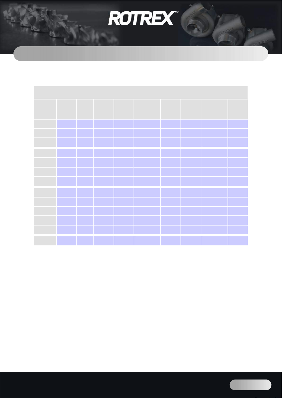
The amount of air delivered by the supercharger and consequently the boost pressure is
determined by the supercharger model and the impeller speed in conjunction with the
engine size and speed. The comparison table above shows the working area of each
supercharger model within the C-range. For compressor maps please refer to the
technical datasheets. If in doubt, please contact your Rotrex supplier.
Regardless of the supercharger type and model, always make sure to run it within its
respective operating speed range specified in the technical datasheet. Exceeding these
speed values will void warranty.
The optimum supercharger for a given application will depend on many variables of which
some are hard to know accurately (e.g., volumetric efficiency or how this will be affected
under boost conditions). This can very well be modelled using advanced engine calculation
tools and theory. However, using a simple “rule of thumb” along with the information
provided here and in the flow maps will be adequate in many cases.
Supercharger comparison table
Model
Input
rotation
direction
Pulley
dia.
[mm]
Air inlet
hose dia.
[mm]
Air outlet
hose dia.
[mm]
Max impeller
speed
[rpm]
Max
pressure
ratio
Max flow
[kg/s]
Power range1
[engine kW]
Max
adiabatic
efficiency
[%]
C15-16 CW3 70-90 60 45 201,500 2.46 0.15 60-125kW
(82-170hp) 70
C15-20 CW3 70-90 60 45 180,000 2.94 0.15 50-120kW
(68-163hp)
75
C15-60 CW3 70-90 60 45 150,000 2.34 0.22 90-175kW
(122-238hp)
74
C30-64 CW3 70-110
60 50 120,000 2.68 0.28 120-235kW
(163-320hp)
72
C30-74 CW3 70-110
60 50 120,000 2.82 0.31 135-255kW
(184-347hp)
72
C30-84 CW3 70-110
76 50 120,000 2.82 0.32 140-265kW
(190-360hp)
72
C30-94 CW
3
CCW2 70-110
76 50 100,000 2.52 0.39 145-320kW
(197-435hp) 71
C38-61 CW3 70-110
76 63 90,000 2.90 0.48 200-410kW
(272-557hp)
73
C38-71 CW3 70-110
76 63 90,000 2.82 0.55 210-455kW
(286-620hp)
75
C38-81 CW3 70-110
76 63 90,000 2.85 0.58 220-485kW
(300-660hp)
72
C38-91 CW3 70-110
76 63 90,000 2.94 0.63 260-530kW
(354-720hp)
75
C38-92 CW3 70-110
89 63 90,000 2.94 0.63 260-530kW
(354-720hp)
75
C38R-112
CW
3
CCW2 75-110
89 63 90,000 3.34 0.84 340-720kW
(455-965hp) 75

Technical Handbook
Rev. 1.6
WWW.ROTREX.COM Page 10 of 41
Choosing the right Rotrex
3.2 Supercharger selection example: boosting 105hp to 150hp
The following example shows the process of supercharger sizing, for a given engine, to
provide a more detailed explanation of how to choose the best supercharger for a given
application. This example is to be seen as a basic guideline and may vary depending on
engine variables.
The key to selecting the right supercharger is to know what air flow and pressure ratio you
will be running. With this information you can go through the supercharger compressor
maps and choose the right model from there.
Generally speaking, a normal gasoline combustion engine will produce about 120hp for
every 0.1 kg/s of air (this figure is highly dependent on engine efficiency and may be
considerably higher or lower depending on engine variables). By inserting the expected hp
figure of the supercharged engine into the formula below, we now get the expected flow.
Flow [kg/s] = hpsupercharged
1200
Since the target power in this example is 150hp, we have the following flow:
150
1200 = 0.125 𝑘𝑔 𝑠
The approximate pressure ratio needed to produce this power on the given engine can be
approximated from the formula below. The pressure losses through the filter, pressure
pipes, intercooler and intake system including the power to drive the supercharger are
approximated to about 15%, thus multiplying by 1.15 in the formula.
PR = hpsupercharged
hpnaturally aspirated × 1.15
This is true only when the engine runs under low to moderate boost (up to 0.7 bar PR
1.7) and assuming the air entering the engine has been cooled to a temperature no more
than 30C above ambient temperature. Any other restrictions in the system (i.e.,
restrictive exhaust system, inlet filter, valve size, ducting etc.) will reduce the expected
boosted power output.
Entering the values from this example we have the following PR:
150
105 × 1.15 = 1.64
After studying the supercharger selection table (above) and flowcharts in the technical
datasheets, we can conclude that the C15-60 is a good match with an adiabatic efficiency
above 72% at the point of 0.125 kg/s and PR 1.64

Technical Handbook
Rev. 1.6
WWW.ROTREX.COM Page 11 of 41
Designing and handling interfaces
4. Designing and handling interfaces
4.1 Pulleys and other drive types
Rotrex provides 8 and 10 ribbed PK-type pulleys ranging from Ø70 to Ø110mm in diameter
in steps of 5mm (i.e., Ø70, Ø75, Ø80...). Check the technical datasheets for available
pulley sizes for specific superchargers. Rotrex highly recommends using standard Rotrex
pulleys. If you for some reason need to use a different design, please follow the technical
information and specifications on pulley design in Section 6.1 and 6.2. This will ensure a
proper coupling and a healthy bearing arrangement. Not following these specifications
voids warranty and may result in permanent damage of the supercharger system and/or
other systems in the vehicle/application.
Repeatedly turning the input shaft on a new unit in the wrong direction (see supercharger
selection table, page 9) will result in detachment of the internal thread connection resulting
in supercharger damage.
Never use an impact wrench when mounting or changing pulleys. Section 6.3 of this
document explains the procedure for assembling and disassembling pulleys.
The supercharger must be delivered with the pulley/pulley adapter pre-assembled to the
installer or end user to avoid claims arising from incorrect pulley assembly.
In case of any questions or doubt don’t hesitate to contact your supplier or Rotrex.
Use the formula in the box below to calculate the pulley size for a given application. The
target impeller rpm, RPMi, should be found using a flow map and target values for pressure
ratio and air flow. Do not exceed the maximum allowed supercharger speed.
𝑅𝑃𝑀=𝑅𝑃𝑀, × Ø𝑃𝑢𝑙𝑙𝑒𝑦× 𝑅𝑎𝑡𝑖𝑜
Ø𝑃𝑢𝑙𝑙𝑒𝑦
or reorganized for pulley diameter...
Ø𝑃𝑢𝑙𝑙𝑒𝑦=𝑅𝑃𝑀, × Ø𝑃𝑢𝑙𝑙𝑒𝑦× 𝑅𝑎𝑡𝑖𝑜
𝑅𝑃𝑀
where subscripts i,e,s denote impeller, engine
and supercharger.
Example:
Engine max speed: 7200rpm
Supercharger: C15-60
Impeller speed: 142krpm
Ratio of C15: 12.67:1
Crank pulley: 123mm
7200 × 12.67 × 123
142000 = 79
By rounding up we get the appropriate
pulley diameter to be 80mm
Note:
C15 drive ratio: 1:12.67
C30 drive ratio: 1:9.49
C38 drive ratio: 1:7.50
C38R drive ratio:
1:6
Pulley size
calculation

Technical Handbook
Rev. 1.6
WWW.ROTREX.COM Page 12 of 41
Designing and handling interfaces
4.2 Belt drives
4.2.1 Belt routing
Due to the apparent simplicity of the belt drive, installers and designers tend to disregard
its importance. The single most frequent source of supercharger installation problems can
be traced back to the belt drive or design and manufacturing of belt drive components
such as brackets, tensioners, pulleys and mounting points. Paying special attention to the
belt drive can improve performance, durability, service life and ease of service
significantly.
To analyse a belt drive properly you should contact a belt manufacturer with detailed
information of all the components in the drive and the conditions it will be run under. From
this, an estimated lifetime and frequency analysis can be made to give a reasonable
evaluation of the durability of the belt drive.
A more simplistic approach can be taken for prototype work. These guidelines are rule of
thumb only and must be accompanied by many hours of extensive testing on multiple
installations to get a true picture of the rigidity of the belt drive.
It is advisable to run the supercharger from a separate belt and crank pulley. Leaving the
vehicle’s existing belt drive untouched reduces the risk of wear and failure of the belt and
subcomponents. For twin charger applications we advise to run each supercharger on a
separate belt to maximize durability.
Belt wrap for low
power accessories
such as water
pumps, alternator,
power steering,
aircon, etc.:
Minimum 90°
Belt span:
Minimum 75mm (~3”)
Maximum 300mm (~12”)
Tensioner position:
On slack side and
perpendicular to
belt with high belt
wrap
Tension force:
75-120N pr.
belt rib
Tensioner travel:
Minimum 3% of
total belt length
Clockwise
example
Belt wrap for high
power pulleys
such as crank and
supercharger:
Optimum 180°
Minimum 120°

Technical Handbook
Rev. 1.6
WWW.ROTREX.COM Page 13 of 41
Designing and handling interfaces
Although quite rare, there are some engines that rotate counter-clockwise. When choosing
a Rotrex supercharger please ensure correct rotational direction of the input, see Section
3.1. By driving the supercharger from the back side of a double-sided belt the rotational
direction is reversed. This way it is possible to install superchargers to counter-clockwise
rotational engines.
The same method can be used to install a supercharger in a mirrored position compared
to the other front-end components so that a clockwise rotating engine drives a
supercharger mounted in a mirrored position from the back side of the belt. This inverts
the driving direction twice, resulting in a clockwise rotating engine and a clockwise rotating
supercharger.
4.2.1 Belt alignment
Belt misalignment is a common source of wear and noise problems. Bracket fixing points
and tolerances including coatings are a source of belt misalignment issues. The following
guidelines will help prevent problems when designing a system.
Angular
Planar
Clockwise vs Counter
-
Clockwise
CW
C
C
W

Technical Handbook
Rev. 1.6
WWW.ROTREX.COM Page 14 of 41
Designing and handling interfaces
A good rule of thumb to keep in mind is that noise which occurs at idling and low speeds
is likely to be due to pulley misalignment. Noise that occurs at high speeds is likely to be
due to belt tension problems. To identify or recreate the noise it is important to find the
true cause and to cure the problem: Use a spray bottle filled with water to mist the belt
lightly. If the noise level recedes for several seconds, then returns louder, a misalignment
problem is likely. If the noise immediately increases after the belt is sprayed, slip is likely.
Besides noise, belt dust and burnt rubber smell are other typical signs of misalignment,
wrong belt tension or other problems in the drive.
To avoid bearing problems with the supercharger or any other front-end accessory it is
imperative that the belt runs within the specified design window. A maximum allowed belt
force overhang is defined as; the middle of the belt must run at a maximum of 23mm from
the supercharger bracket face. See Section 6.1 for a specification of the belt overhang
limitations.
Wrong
belt placement
Good
belt placement

Technical Handbook
Rev. 1.6
WWW.ROTREX.COM Page 15 of 41
Designing and handling interfaces
4.3 Brackets
Section 6.4 of this document provides the critical dimensions needed for the construction
of the main bracket. Following these specifications is important to ensuring adequate
fixation of the supercharger and pulley/belt at running conditions. In addition, the
following guidelines are also important:
Choose geometry and material that ensures optimum alignment, stability, and
durability
Include a minimum of 3 strong fixing points to help prevent excessive vibration and
bending during operation. Remember to avoid materials that will corrode when
mounted onto aluminium
Consider possible manufacturing tolerances on engine anchoring points and avoid
rough cast surfaces since this can result in considerable belt misalignments that
can cause belt slippage, noise and even failure
Include surface treatments to prevent corrosion and improve looks. Remember
that some surface treatments build a considerable layer on top of the material, and
this should be accounted for to remain inside the specified dimensional tolerance
range

Technical Handbook
Rev. 1.6
WWW.ROTREX.COM Page 16 of 41
Designing and handling interfaces
4.4 Lubrication circuit
The special Rotrex oil system is an integral part of the design and function of the Rotrex
C-type supercharger. These superchargers have been developed and extensively tested
with special Rotrex traction fluid. To maintain the ultimate level of performance and
durability it is vital that the unit is run exclusively with Special Rotrex traction fluid.
The picture shows the Rotrex universal oil set. It contains everything needed (hoses,
fittings, filter, cooler and canister) for your application development and
commercialization. We strongly recommend using these oil sets as they have gone
through extensive testing before approval. Consult your distributor or Rotrex if you need
to modify the standard oil set in any way (even if the change seems trivial). Any deviation
from the universal oil set and its standard setup needs to be approved by Rotrex in writing
for the supercharger to be covered by warranty.
Dual action filter
(magnet-paper)
High quality
quick fit
clamps
Aluminum canister
with breather &
dipstick
Cooler
fittings
Banjo
connections
High quality
hose
(iD=8mm)
Oil cooler
Mounting
brackets
Special Rotrex
traction fluid
<1 liter>

Technical Handbook
Rev. 1.6
WWW.ROTREX.COM Page 17 of 41
Designing and handling interfaces
4.4.1 Designing a good lubrication circuit
The lubrication circuit path chosen within the engine bay needs to ensure that oil
temperature at the inlet of the supercharger never exceeds 80°C (176°F) as higher inlet
oil temperature will damage the supercharger. Therefore, it is advised to locate the cooling
elements (main cooler and canister) in well ventilated location. The oil cooler alone should
be able to cool the oil sufficiently.
The supercharger must be positioned above all oil system components (filter, canister, oil
cooler and oil lines) to prevent any potential oil leakage from the supercharger. Remember
that the canister needs to be accessible for service and maintenance purposes.
When routing the oil lines, care must be taken to prevent kinks, rubbing and cuts on the
oil lines since leakage could result in permanent damage of supercharger system and/or
other systems in the vehicle. To avoid problems, follow these specifications:
Oil Cicuit
Installation
Example
Canister:
Below SC
Filter:
Between
canister and
SC oil inlet
Oil Cooler:
Between SC outlet
and canister, with
access to cooling air Oil lines:
Good routing, no
contact with sharp
edges or hot
components

Technical Handbook
Rev. 1.6
WWW.ROTREX.COM Page 18 of 41
Designing and handling interfaces
The oil lines and the oil system components (filter, canister and cooler) must be
placed below or level with the supercharger shaft
Oil lines must be routed in safe distance from the exhaust system or other hot parts
to prevent excessive heating of the oil and melting of the oil hoses
Make sure there is clearance to other moving parts such as the radiator fan, belts,
and pulleys
When creating the oil circuit, use only Rotrex standard oil hoses
Always use special hose cutters or a sharp knife when cutting the oil hoses to
prevent damage of the hoses during mounting. If a hose is damaged during
assembly, it must be replaced. Using saws, grinders or other abrasive cutters is
prohibited
To prevent restricted oil flow only use large radius bends and make sure there are
no kinks in the oil lines
Engine vibration and movement must be considered when routing the oil lines
It is important to place the oil cooler where the risk of clogging (debris, stones,
sand etc.) can is minimal. If the cooler is clogged it loses function and will overheat
the supercharger, leading to failure
During assembly it is important to prevent debris and other contamination from
entering the oil system
Maximum oil system length (including the oil cooler and canister) is 6.0 m
Maximum allowable elevation between oil system components is 1.0 m
Failure to comply with these specifications can compromise the overall reliability and may
result in permanent damage of the supercharger and/or other systems in the application.
If the application requires customized oil routing (not using the parts included in the Rotrex
package seen in Section 4.4), please contact your Rotrex supplier.
Positioning!
To prevent oil leaks, it is of utmost importance that the oil cooler, oil filter and the oil
canister with its cap are placed below or level with the supercharger shaft.

Technical Handbook
Rev. 1.6
WWW.ROTREX.COM Page 19 of 41
Designing and handling interfaces
3 With a pair of pliers
compress a hose clamp and
slide it over one end of the
hose. Press a banjo fitting
into the hose end and
secure it with the hose
clamp.
5 Now find a suitable place for
the oil filter somewhere along
the
oil inlet hose. Cut the hose
using scissors or a sharp
knife. Again, slide a hose
clamp over each end of the
hose.
4 With the supercharger
properly in place fit one end
of the hose to the
oil inlet using the banjo
fitting and banjo bolt. Make
sure to use a copper washer
on each side of the banjo
fitting to prevent leaks.
2
Mount the oil cooler in front of
other coolers in a location with
good air flow. Place the oil
cooler below or level
with the
supercharger’s shaft. The
threads for the fittings must be
facing upwards to prevent air
pockets.
1 Place the oil canister with the
cap below or level with the
supercharger’s shaft. Use the
bracket supplied in the oil set.
Make sure the canister is
placed upright. Leave the
plastic plugs in place to
prevent debris from entering
the system.
6 Now press the filter studs
into the hose ends as shown
and secure with hose
clamps. Observe the flow
direction of the filter!
Following the same method,
continue fitting the
remaining parts of the oil
system.
4.4.2 Installation, start-up, and maintenance
Please follow these recommendations when installing the oil circuit:
This manual suits for next models
12
Table of contents
Other Rotrex Batteries Charger manuals