Rotronic AG
Bassersdorf, Switzerland
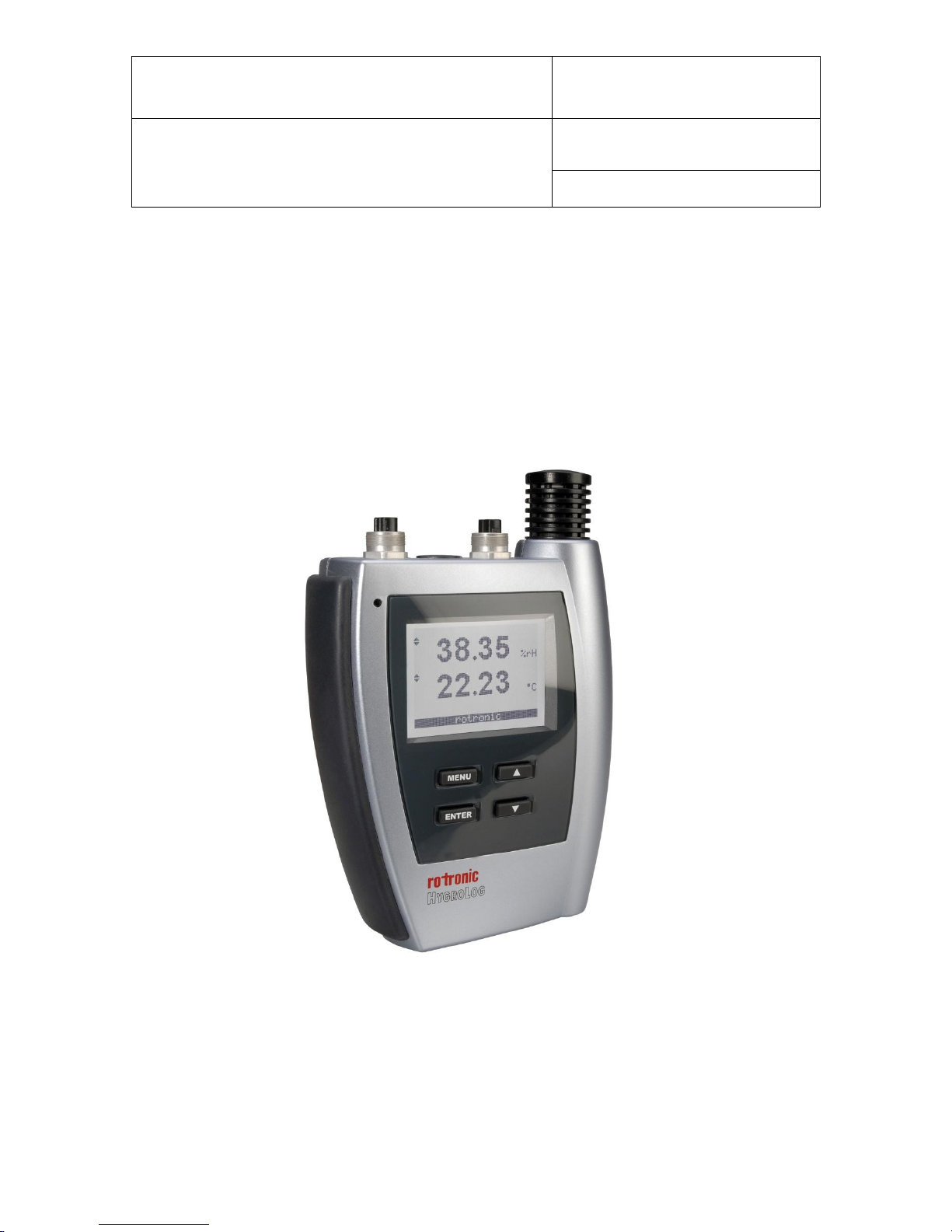
HygroLog HL-NT data logger:
instruction manual
© 2009-2012; Rotronic AG IN-E-HL-NT-V2_12
Table of contents:
1. Overview.................................................................................................................................. 3
1.1 General................................................................................................................................ 3
1.2 Compatibility with previous models of probes and docking stations ................................... 4
2. General description of the HygroLog HL-NT....................................................................... 5
2.1 Models ................................................................................................................................. 5
2.2 Required accessories.......................................................................................................... 5
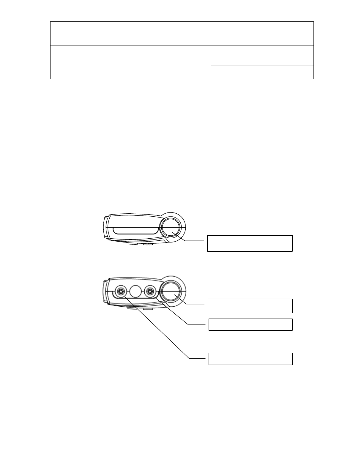
2.3 HygroLog HL-NT inputs....................................................................................................... 5
2.4 Power supply ....................................................................................................................... 8
2.5 Memory card........................................................................................................................ 9
2.6 LED Indicators ................................................................................................................... 10
2.7 Beeper ............................................................................................................................... 10
2.8 HygroLog HL-NT functions................................................................................................ 10
2.9 HygroClip 2 probe functions .............................................................................................. 13
2.10 Event tracking.................................................................................................................... 14
2.11 Operating limits (electronics only) ..................................................................................... 16
3. Docking stations for the HygroLog HL-NT ........................................................................ 17
3.1 Models ............................................................................................................................... 17
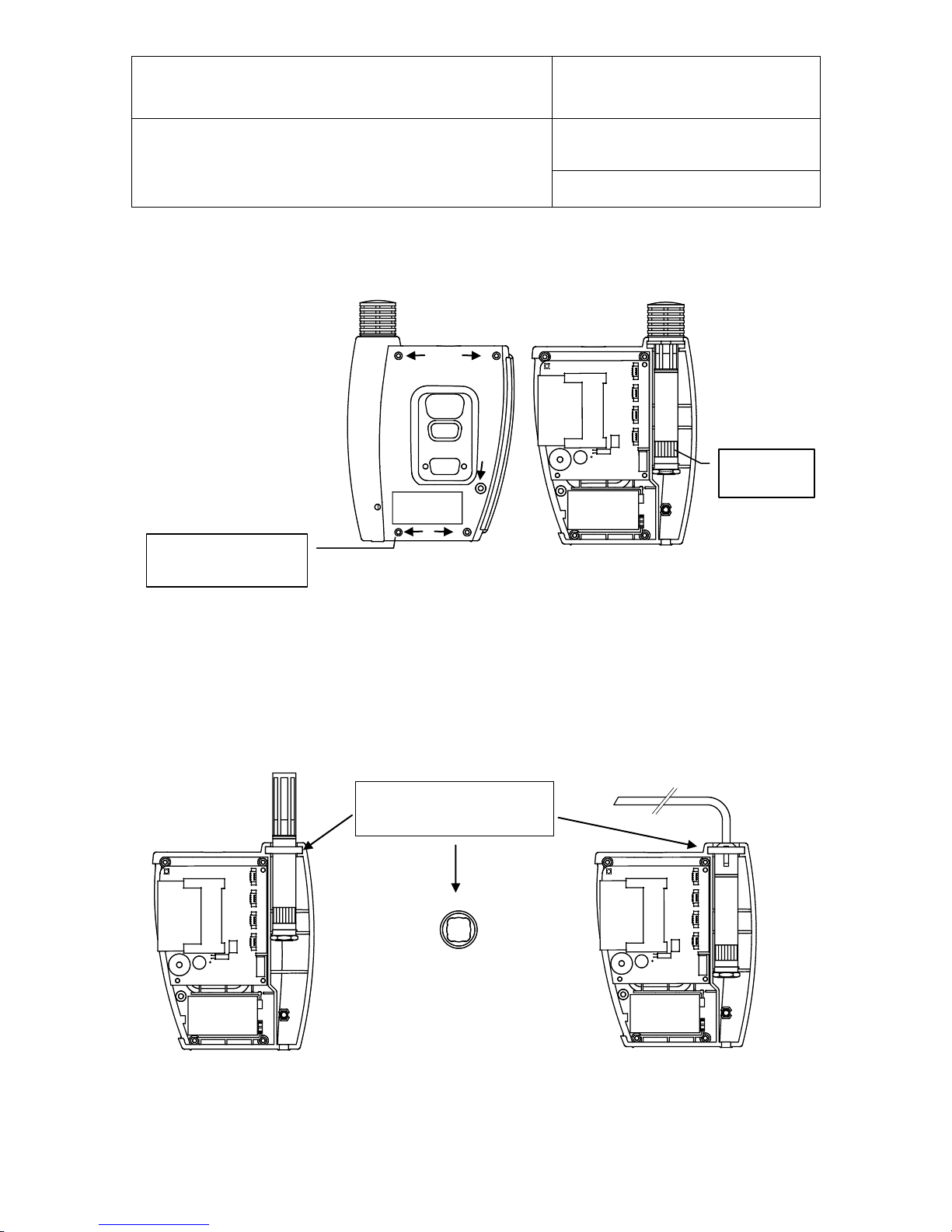
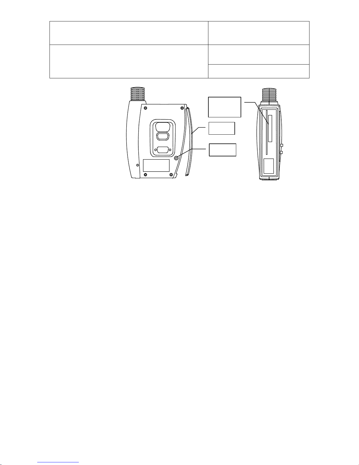
3.2 Installation.......................................................................................................................... 20
3.3 Docking station inputs........................................................................................................ 25
3.4 Relay contacts................................................................................................................... 26
4. Pin-out diagrams.................................................................................................................. 26
5. HW4 software........................................................................................................................ 28
5.1 Computer/Operating System Requirements ..................................................................... 28
5.2 Operating System Compatibility ........................................................................................ 29
5.3 Settings and functions accessible only with HW4 ............................................................. 29
6. ERES regulatory compliance.............................................................................................. 30
7. Getting started...................................................................................................................... 31
8. Stand-alone operation ......................................................................................................... 31
8.1 Operating modes............................................................................................................... 31
8.2 Display and keypad ........................................................................................................... 31
8.3 Display modes................................................................................................................... 33
8.4 Settings and functions accessible from the Keypad.......................................................... 33
8.5 Internal function menu (models with display and keypad)................................................. 34
9. Operation on a network ....................................................................................................... 37
9.1 Baud rate and communications protocol compatibility requirements................................ 37
9.2 Ethernet local area network............................................................................................... 37
9.3 RS-485 multi-drop network................................................................................................ 38
9.4 General wiring guidelines .................................................................................................. 39
9.5 Guidelines for RS-485 wiring............................................................................................. 40
10. HygroClip probe adjustment procedures ..................................................................... 41
10.1 Single Point adjustment..................................................................................................... 41
10.2 Multi-Point adjustment....................................................................................................... 42
11. Warnings and useful tips................................................................................................ 42
12. Communications protocol.............................................................................................. 43
13. Firmware updates............................................................................................................ 43
14. Specifications .................................................................................................................. 44
15. Accessories...................................................................................................................... 47
16. Supporting documents ................................................................................................... 47
17. Document releases.......................................................................................................... 48