ROTZLER TITAN TI 5 User manual

4000021245 Rev. A10.10.2019
Hoisting winch
TITAN
TI 5
INSTALLATION IMPERIAL DATA

1 General
2 4000021245
Original Installation Manual
The general installation manual must be stored in close
proximity to the winch and be available to trained personnel
at any time.
Before starting any work installation manual must be read
in full and understood. All safety instructions must be ob-
served and followed.

1 General
4000021245
3
Table of Contents
1 General........................................................................4
1.1 Introduction...................................................................4
1.2 Copyright ......................................................................5
1.3 Warranty....................................................................... 5
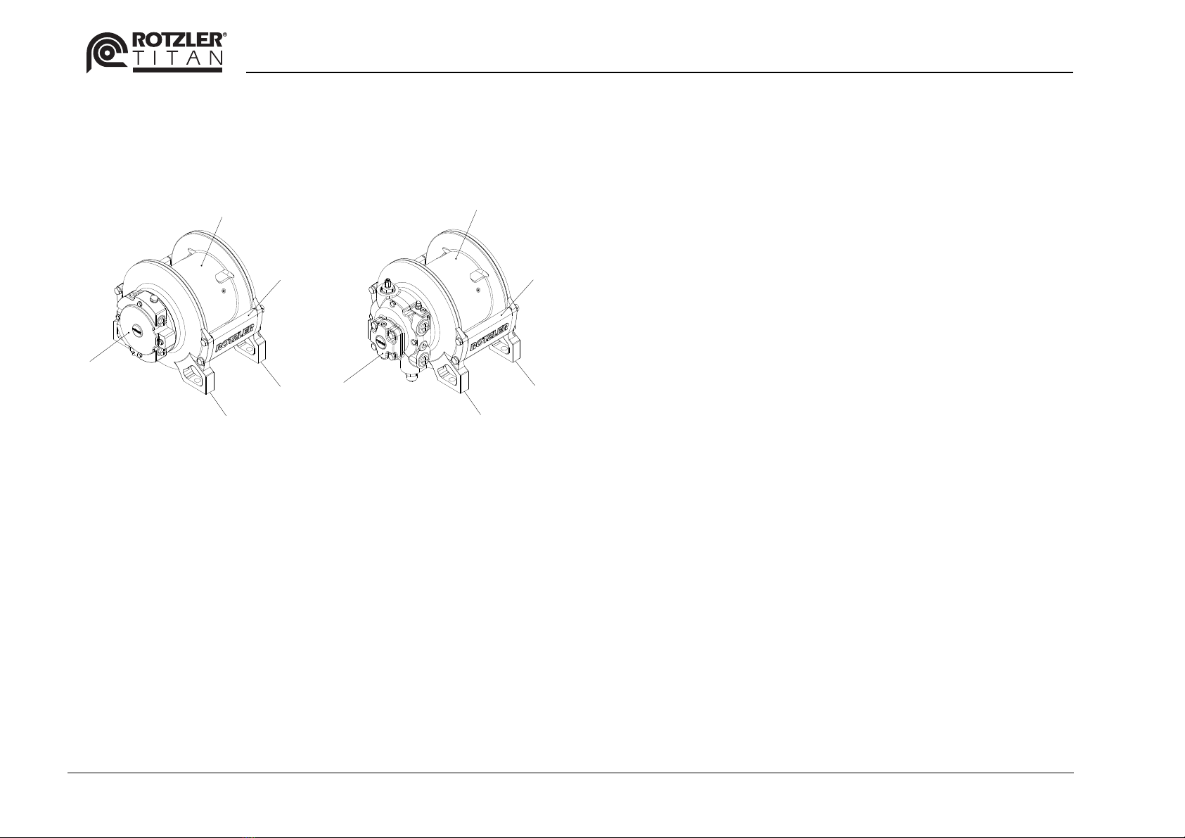
2 Basic winch.................................................................6
2.1 Winch description ......................................................... 6
2.2 Cooperation of the Components...................................6
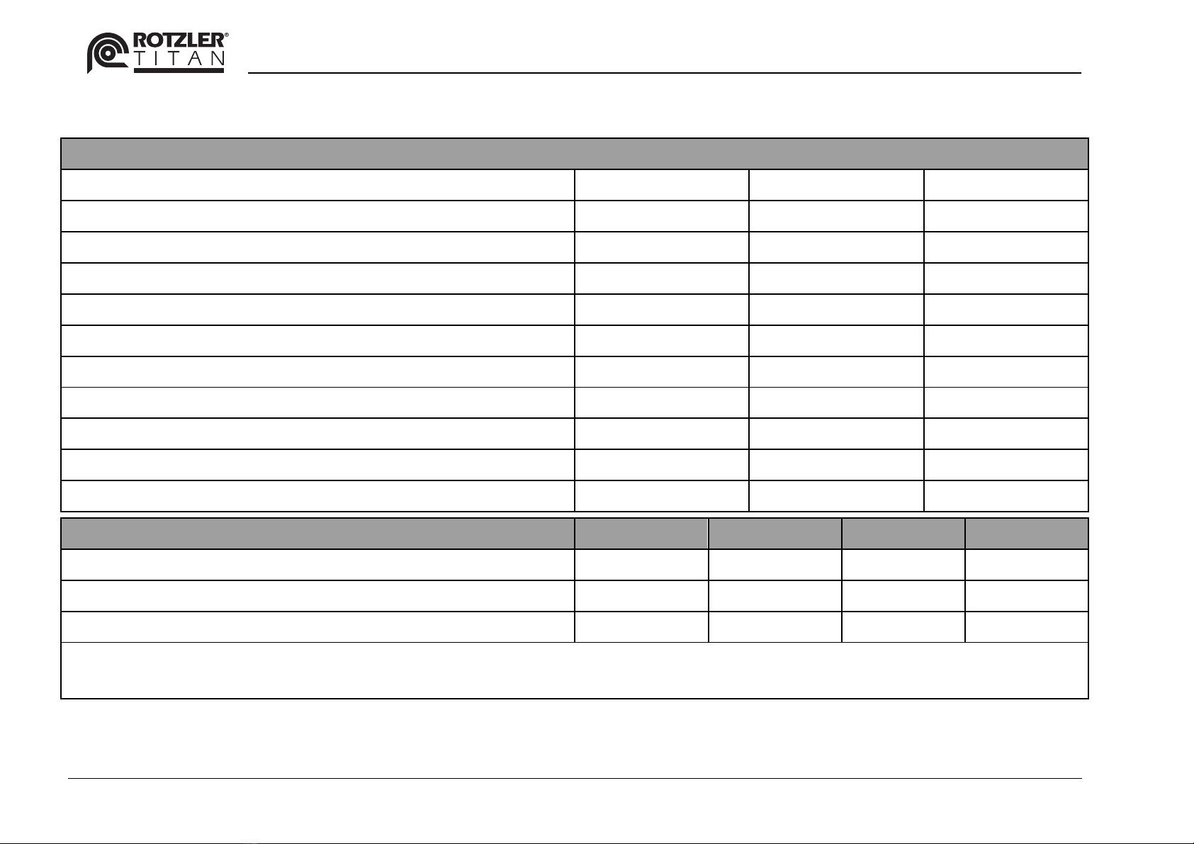
2.3 Basic winch dimensions ...............................................7
2.4 Basic winch technical data ........................................... 8
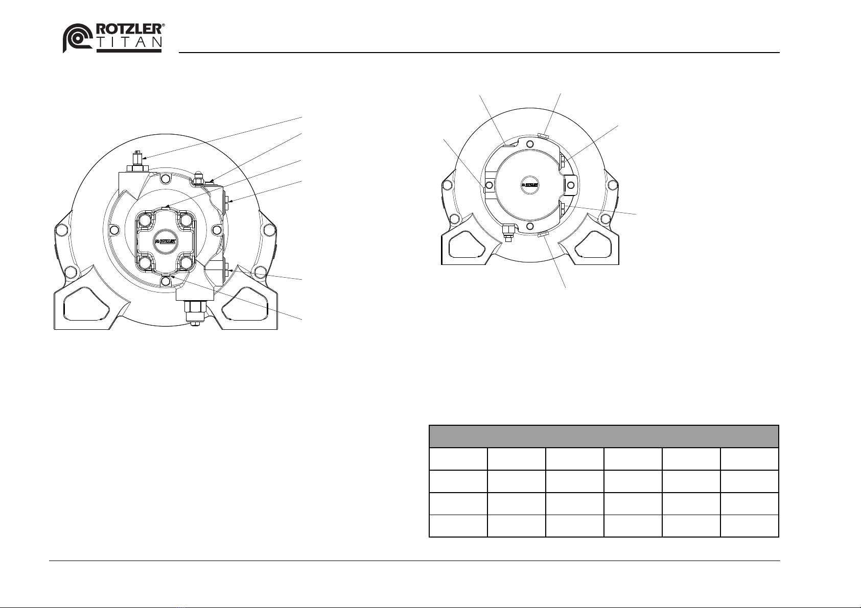
3 Interfaces ....................................................................9
3.1 Mechanical interface.....................................................9
3.2 Hydraulic interface...................................................... 10
3.3 Electric interface......................................................... 12
4 Options...................................................................... 13
4.1 Pressure roller ............................................................ 13
4.2 Rope end control ........................................................ 14
4.3 Emergency brake release........................................... 15
4.4 Break test valve.......................................................... 15
4.5 Ropes ......................................................................... 17
5 TITAN order code ..................................................... 18
6 Safety......................................................................... 19
6.1 Intended use............................................................... 19
6.2 Identification of dangers and notice ............................19
7 Work safety ...............................................................20
7.1 Safety instructions regarding winch installation ..........20
7.2 Safety instructions when handling ropes.....................20
7.3 Safety instructions for hydraulic installation ................21
7.4 Personal protective equipment (PPE) .........................22
7.5 Danger points at winch ...............................................22
7.6 Protective devices.......................................................23
8 Installation.................................................................24
8.1 Handling, transport, storage........................................24
8.2 Mechanical installation................................................25
8.3 Hydraulic installation ...................................................27
8.4 Inspection after installation .........................................30
8.5 Disassembly, disposal and environmental protection .31
9 Options ......................................................................32
9.1 Emergency brake release ...........................................32
9.2 Brake test valve ..........................................................34
9.3 Rope end control.........................................................35
10 Maintenance ..............................................................38
10.1 Maintenance plan........................................................38
10.2 Maintenance procedure ..............................................40
10.3 Service life and general overhaul................................45
11 Troubleshooting........................................................46

1 General
4 4000021245
1 General
The installation manual is written for the winch installer.
Winch installer is responsible for the installation of the
winch per this manual. OEM manufacturers must provide
manuals for their complete device including the winch.
1.1 Introduction
This manual contains important information on the installa-
tion, operation and maintenance of the ROTZLER TITAN
winch.
•ROTZLER HOLDING GmbH +Co. KG
is not liable for any damage or malfunction resulting
from non-observance of ROTZLER installation and
maintenance instructions.
•ROTZLER HOLDING GmbH + Co. KG reserves the
right to make technical modifications.
•If problems arise while installing or servicing the winch,
please contact ROTZLER Customer Support.
CUSTOMER SUPPORT EMEA
Customer Support Germany
Phone
+49 7627 701 0
www.rotzler.com
CUSTOMER SUPPORT South Asia Pacific
Customer Support India
Phone
+91 80 2839 2599
www.rotzler.com
CUSTOMER SUPPORT East Asia Pacific
Customer Support Korea
Phone
+82 55 282 5067
www.rotzler.com
CUSTOMER SUPPORT AMERICAS
Customer Support America
Phone
+1 604 940 7134
www.rotzler.com
Customer Support Canada
Phone
+1 604 940 7134
www.rotzler.com

1 General
4000021245
5
1.2 Copyright
ROTZLER HOLDING GmbH + Co. KG holds the copyright
to this manual. This manual contains texts, procedures, fig-
ures and drawings of a technical nature whose partial or
complete reproduction, distribution or unauthorized use for
competitive purposes or communication to others is strictly
prohibited.
Company addresses:
ROTZLER HOLDING GmbH + Co. KG
Robert-Bosch-Strasse 4
79585 Steinen
Germany
Phone: +49 7627 701 0
Fax: +49 7627 701 166
www.rotzler.com
1.3 Warranty
Warranty claims are only accepted under the following
conditions:
•The winch unit and accessories are used according to
their intended use.
•All instructions in this installation manual have been
considered.
•Only original ROTZLER spare parts have been used.
•Maintenance and inspection intervals have been ob-
served.
•The installation of the winch unit has been carried out in
accordance with the instructions.

2 Basic winch
6 4000021245
2 Basic winch
2.1 Winch description
4
5
3
2
1
Fig. 1 TITAN winch with pis-
ton motor
1
Piston motor
2
Primary base
3
Final base
4
Drum
5
Spacer bar
1
2
3
5
4
Fig. 2 TITAN winch with
gear motor
1
Gear motor
2
Primary base
3
Final base
4
Drum
5
Spacer bar
2.2 Cooperation of the Components
The winch is driven by a hydraulic motor (1). The hydraulic
motor is mounted to the frame of the winch which consists
of primary base (2), final base (3) and spacer bars (5).
The frame also supports the drum (4). The drum contains
the planetary gears which connect the motor drive shaft to
the drum.
The winch is equipped with a spring loaded and hydrau-
lically released holding brake. The holding brake is sepa-
rated from the drive of the winch by a freewheel.
The holding brake is kept closed when lifting a load. This
allows accurate load positioning.
When lowering a load the holding brake is hydraulically re-
leased. The additionally installed counter balance valve in-
side the motor allows controlled load lowering.

2 Basic winch
4000021245
7
2.3 Basic winch dimensions
0.80" ± 0.04"
14.20"
19.88" max.
Ø11.00" ± 0.02"
17.05" max.
12.18" ± 0.08"
13.84" -0.01"/+0.03"
15.75" max.
A
0.80" ± 0.04"
Fig. 3 Dimensions of basic winch [inch]

2 Basic winch
8 4000021245
2.4 Basic winch technical data
Data based on basic winch without options
Motor type GM085* GM107* PM049*
displacement [cm³] 85 107 49
required max. pressure pmax at motor [PSI] 2800 2300 4300
max. return flow pressure py max [PSI] 200 200 200
max. back pressure px max [PSI] 75 75 75
max. case drain pressure pl max [PSI] 200 200 25
max. oil flow Qmax [US GPM] 61 76 34
min. oil flow Qmin [US GPM] 12 15 3
sound pressure [dB] 91 91 91
weight approx. [lb] 410 411 430
dimension A max. [inch] 22.52 23.03 20.28
Data per rope layer 1st 2nd 3rd 4th
max. hoisting force [lbf] 12300 11100 10100 9300
max. rope speed [ft/min] 152 167 183 198
max. accumulated rope storage [ft], rope Ø 5/8“ 56 117 184 256
* At gear motors (GM) case drain line is required when return line backpressure exceeds 200 PSI.
* At piston motor (PM) case drain line is mandatory.
Tab. 1 Technical data of basic winch [data can vary according to options]
Performance data valid for hydraulic oil viscosity of 39cst at ambient temperature of 73,4°F and Qmax.

3 Interfaces
4000021245
9
3 Interfaces
3.1 Mechanical interface
0.5
2
1
1
X
A
H
V
Fig. 4 Winch mounted on fixing plate
1Screws
2Fixing plate
AFixing surface
HHorizontal axis
VVertical axis
Mounting
fasteners Qty.
Size
Quality
Tightening
torque
Measure
X
standard
fasteners 4 7/8
UNC
Grade
5 328 lbf/ft 0.8 inch
stainless
steel fas-
teners
4 7/8
UNC
A4-80 451 lbf/ft 0.8 inch
Tab. 2 Technical data of recommended fasteners

3 Interfaces
10 4000021245
3.2 Hydraulic interface
NA
L1
V1 / V2
BR
V2 / V1
L2
Fig. 5 Hydraulic connections of gear motor
V1/V2 Return / Pressure oil connection in hoisting di-
rection
L1 / L2 Case drain connection
NA Emergency brake release port (option)
BR Break relief port
NA L1
V1/V2
V2/V1
L2
BR
Fig. 6 Hydraulic connections of piston motor
V1/V2 Return / Pressure oil connection in hoisting di-
rection
L1 / L2 Case drain connection
NA Emergency brake release port (option)
BR Break relief port
Connection ports for motor ("BSPP" thread)
V1 V2 L1 L2 BR
GM107 G1-1/2G1-1/2G1/4 G1/4 G1/4
GM085 G1-1/2 G1-1/2 G1/4 G1/4 G1/4
PM049 G1 G1 G1/2 G1/2 G1/8
Tab. 3 Hydraulic connection port sizes

3 Interfaces
4000021245
11
Hydraulic circuit TI 5 gear motor without option
L
BR
L2
V2 V1
L1
1
2
4
5
6
7
PR
9
8
Fig. 7 Hydraulic diagram without option
(1)
(2)
(4)
(5)
(6)
(7)
(8)
(9)
R
P
L
BR
winch
hydraulic brake (hydraulically released)
hydraulic motor
counter balance valve
control valve*
pressure relief valve*
hydraulic pump*
return filter*
return line to reservoir
pressure line
case drain line
brake relief port
V1
V2
L1 / L2
return oil connection for direction „ROPE IN“
pressure oil connection for direction „ROPE IN“
case drain connection
* not supplied by ROTZLER

3 Interfaces
12 4000021245
3.3 Electric interface
3.3.1 Rope end control:
Technical data: max. voltage 33 V DC / max. permanent
current 10 A.
core I
core II
core III
Fig. 8 Rope end sensor connection
Regarding the assembly it has to be secured that through
an interruption of the power supply between cable cores I
and II, the winch is stopped in direction „OUT“, Core III not
used for rope end.

4 Options
4000021245
13
4 Options
4.1 Pressure roller
Fig. 9 Pressure roller, view
from bottom
20.35" Max.
Fig. 10 Dimension with pres-
sure roller
Added weight for Pressure
Roller Option
Gear
motor
GM085
Gear
motor
GM107
Piston
motor
PM049
weight pressure roller [lb] approx. 11.9
Tab. 4 Data with pressure roller
Pressure roller:
The pressure roller supports proper spooling of the rope on
the drum. It is mechanically fastened to the winch frame. Its
position is always on the opposite side to the rope inlet.
Application benefits:
The pressure roller improves the correct spooling of the
rope. It reduces the slack and assists layering of the rope.
•increased the life time of the rope
•reduced down time of the winch
•higher operation time

4 Options
14 4000021245
4.2 Rope end control
Rope end control consists of a roller and a switch to detect
if limit of safety wraps are reached.
Fig. 11 Pressure roller incl.
rope end control, view
from the top
20.35" Max.
Fig. 12 Dimensions with
pressure roller and
rope end control
Added weight for pressure
roller with rope end control
Gear
motor
GM085
Gear
motor
GM107
Piston
motor
PM049
weight pressure roller incl. rope
end control [lb] approx. 11,9
Tab. 5 Data with pressure roller and rope end control
Rope end control:
The rope end control is mechanically attached to pressure
roller housing. The optional rope end control is only availa-
ble in combination with the pressure roller. The threshold
signal „rope end“ is emitted by an electric switch.
Application benefit:
Signal of rope end at either:
•3 rope wraps or
•5 rope wraps
Correctly utilized the rope end signal can be used to pre-
vent spooling in the wrong direction.
Different standards require a rope end control.

4 Options
4000021245
15
4.3 Emergency brake release
The emergency brake release (EBR) option allows releas-
ing the brake and lowering loads larger than 900 lbs with
an auxiliary hydraulic supply. In case of failure of the main
hydraulic system, it allows safe lowering of a suspended
load.
Application benefit:
In an emergency situation the operator can easily unload
the crane to secure the system and to prevent damage.
Emergency brake release interface:
The emergency brake release valve is integrated in the hy-
draulic motor housing.
Connection ports ("BSPP" thread)
NA G 1/4
Tab. 6 Hydraulic connection port sizes with external brake re-
lease
weight added with optional
emergency brake release
Gear
motor
GM085
Gear
motor
GM107
Piston
motor
PM049
weight shuttle valve plus exter-
nal brake release [lb] approx. 1.1
Tab. 7 Data with optional external brake release
4.4 Break test valve
Using the optional Brake Test Valve, the mechanical brake
can be tested by applying pressure directly to the winch
motor only.
For the hydraulic diagram please refer to Fig. 13.

4 Options
16 4000021245
Hydraulic circuit gear motor with option EBR and brake
test valve
12
O I
L
6
7
9
P R
8
1
10
11
5
4
3
2
L1
V1
V2
L2
BR NA
13
ø1
Fig. 13 Hydraulic diagram for gear motor with options
(1)
(2)
(3)
(4)
(5)
(6)
(7)
(8)
(9)
(10)
(11)
(12)
(13)
R
P
L
BR
winch
hydraulic brake (hydraulically released)
brake test valve - optional
hydraulic motor
counter balance valve
control valve*
pressure relief valve*
hydraulic pump*
return filter*
auxiliary hydraulic system*
shuttle valve - optional (if emergency brake re-
lease is used)
control valve for bypass*
check valve, cracking pressure 15 psi*
return line to reservoir
pressure line
case drain line
brake relief port
V1
V2
L1 / L2
NA
return oil connection for direction „ROPE IN“
pressure oil connection for direction „ROPE IN“
case drain connection
emergency brake release port
* not supplied by ROTZLER

4 Options
4000021245
17
4.5 Ropes
C
A
B
D
Fig. 14 Drawing of rope
Why should customer use a rope from ROTZLER?
ROTZLER standard ropes are selected for their tensile
strength and wrap properties. All ropes for TITAN winches
are non-rotating ropes. Safe winch operation is guaranteed
over a long life span.
Application benefit:
ROTZLER ropes can be easily ordered for each winch
model and meet the highest safety standard for marine,
loading and service cranes.
Rope interface:
ROTZLER ropes are connected to the winch by a rope
lock. Adding a rope end switch to the winch ensures that a
minimum 3/5 wraps are always present.
Standard rope
diameter [inch] 5/8
length [ft] 250
weight [lb] 216
class of rope strength 2160
min. breaking strength [lbf] 55975
related working load at safety factor 3.55 [lbf] 15700
spinning loss factor 0.797
A [inch]
+0.1968 / - 0.0393 1.57
B [inch] 3.74
C [inch] 1.06
D max. [inch] 0.32
Tab. 8 Data of standard rope

5 TITAN order code
18 4000021245
5 TITAN order code
Motor Layout
counter clockwise,
rope overwound
3.
1. 2. 3.
motor ports case drain ports
110
0 1
DIG – Binary Code
7
111000 001 010 011
Rotation direction (rope in) / general layout
clockwise,
rope underwound
4. clockwise,
rope overwound
1.
counter clockwise,
rope underwound
2.
Motor port
left side
0.
6
Motor port
on top
Motor port
right side
Motor port
on bottom
04. = Black + extra coat
52 3 4
100 101
TI. = TITAN
05. = TITAN 12400 lbf
0. = 12.2 inch
5X. = MCD Step 5 separated rope end & torque signal
Paint finish
00. = Primer
01. = White
02. = Black
03. = White + extra coat
15. = Pressure roller, rope end control activated with
Version of Code
Construction
Type
5 rope wraps
4X. = MCD Step 4 combined rope end & torque signal
3.
00.3. TI. 05. 0. DIG
13. = Pressure roller, rope end control activated with
3rope wraps
00. G 085.M 00. 00.1. 0. 00.
Drum width
G 085.M = 85 ccm gear motor
G 107.M = 107 ccm gear motor
P 049.M = 49 ccm piston motor
0
Rotation direction
and general layout
For position of rotation direction/general layout see details
on the right
Motor layout For position of motor ports see details on the right
MCD type
00. = No MCD
2X. = MCD Step 2 overload 1 point sensoring @ rope in
3X. = MCD Step 3 overload 2 point sensoring @ rope in
00. = No grooves
13. = Grooves for 5/8" rope
Grooves
Pressure roller and
rope end control
00. = No pressure roller, no rope end control
10. = Pressure roller, no rope end control
MCD - Variants X
1
2
with cable and crimped cable ends
with cable and plug “Deutsch type, 6 lines”
with cable and plug “Sure Seal type 3 lines type”
Rope
00. = No rope
13. = Imperial rope ( length 250 ft, diameter 5/8", MBF 55970 lbf)
Digital Code (DIG) 0. .... 7
CC
CW
CC
CW
(available with
pressure roller and
rope end control
only)
Motor
displacement
only available at MCD 4
DIG – Parameters
Standard fasteners
Stainless fasteners
Without emergency brake release
With emergency brake release
0
1
1
2
Without brake test valve
0
1
With brake test valve
4
0
1(only available at gear motors)

6 Safety
4000021245
19
6 Safety
The Installation manual must be read in full, and safety in-
structions must be observed.
6.1 Intended use
The intended use of the ROTZLER TITAN winches is hoist-
ing and lowering of freely suspended loads. Pulling of loads
adhering to the ground and passenger transport are prohib-
ited.
ROTZLER winches must be used only according to intend-
ed use. Any other use is prohibited.
Local regulations for winches must be observed.
ROTZLER winches are not approved for use in potentially
explosive areas.
Conversions and modifications to winches are not ap-
proved. Only original ROTZLER spare parts are to be used
for repairs.
6.2 Identification of dangers and notice
DANGER!
…warns of a dangerous situation that will result in
death or potentially fatal injury if not prevented.
WARNING!
…warns of a dangerous situation that may result
in death or severe injury if not prevented.
CAUTION!
…warns of a dangerous situation that may result
in light to moderate injury if not prevented.
ATTENTION!
…warns of a situation that will result in damage or
destruction of property if not prevented.
NOTE!
…is used for tips and other useful information
which simplify operating the winch.

7 Work safety
20 4000021245
7 Work safety
7.1 Safety instructions regarding winch in-
stallation
DANGER!
Risk of injuries!
Installing winches can cause dangerous situations
with personal injuries.
The installing and maintenance personnel must
have read and understood the installation
manual.
The installing and maintenance personnel must
wear the obligatory personal protective equip-
ment.
WARNING!
Risk of injuries!
Noise can cause hearing loss
Wear ear protection when a noise level of more
than 80 dB(A) could be reached at the operat-
ing site.
7.2 Safety instructions when handling
ropes
DANGER!
Risk of injuries!
Wrong handling of loaded wire ropes can cause
breakage of the rope causing dangerous situa-
tions.
If the rope is attached and not tensioned, it is
mandatory to build up the tension slowly during
rope reel in. The movement of the load has to
be initiated with the lowest speed available.
When reeling in the rope jerkily, e.g. attach-
ment parts and attachment points can loosen
abruptly.
If the winch is operated under load, three/five
safety wraps (depending on winch type) have
to remain on the rope drum.
The load on the rope must not be rotated if a
load hook without a roller bearing is used (i.e.,
a loaded hook that cannot be rotated under
load). Rotating the load on the rope can lead to
breakage of the rope
Table of contents
Popular Winch manuals by other brands

haacon
haacon KWE 250 operating instructions

Harken
Harken 32.2 Two Speed Winch Installation service

Ribimex
Ribimex RIBITECH PE12V User and maintenance manual

Farmi Forest Corporation
Farmi Forest Corporation JL 601 Operating, Maintenance and Spare Parts Manual

Wahlberg
Wahlberg 380 user manual

Allied Systems
Allied Systems W12E operating manual