Roundup VS-250 User manual

P/N 1010998 Rev. C 11/12
VARIETY STEAMER
Models VS-250
Owner’s Manual
MANUFACTURING
NUMBERS:
9100260
9100261
9100262
A
S
D
L
I
S
T
E
CM
O
I
N
N
I
T
A
T
C
T
I
S
L
US
E
D
D
L
I
S
T
E
C US
I
N
T
E
R
T
E
K

VARIETY STEAMER (VS-250)
2P/N 1010998 Rev. C 11/12
General
The Variety Steamer produces steam using plain tap
water for quick heating and reconstituting of food items.
Simple push-button action delivers a fully adjustable
impulse of steam. Because the amount of steam is
consistent, it removes the guesswork and produces a
uniform finished product from one operator to the next.
This manual provides the safety, installation, and oper-
ating procedures for the Variety Steamer. We recom-
mend that all information contained in this manual be
read prior to installing and operating the unit.
Your Variety Steamer is manufactured from the finest
materials available and is assembled to Roundup’s
strict quality standards. This unit has been tested at
the factory to ensure dependable trouble-free
operation.
OWNER INFORMATION
TABLE OF CONTENTS
IMPORTANT! Keep these instructions for future reference. If the unit changes ownership,
be sure this manual accompanies the equipment.
Warranty Information
Please read the full text of the Limited Warranty in this
manual.
If the unit arrives damaged, contact the carrier imme-
diately and file a damage claim with them. Save all
packing materials when filing a claim. Freight damage
claims are the responsibility of the purchaser and NOT
covered under warranty.
The warranty does NOT extend to:
• Damagescausedinshipmentordamageas
result of improper use.
• Installationofelectricalservice.
• Normalmaintenanceasoutlinedinthismanual.
• Malfunctionresultingfromimpropermaintenance.
• Damagecausedbyabuseorcarelesshandling.
• Damagefrommoistureintoelectrical
components.
• Damagefromtamperingwith,removalof,or
changing any preset control or safety device.
Owner Information .....................................................2
General......................................................................2
Warranty Information .................................................2
Service/Technical Assistance ....................................3
Important Safety Information ....................................4
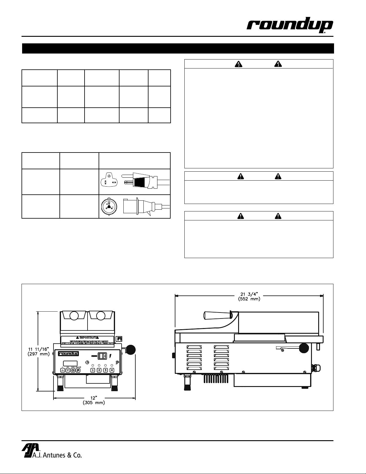
Specifications .............................................................6
Electrical Ratings.......................................................6
Electrical Cord & Plug Configurations .......................6
Shipping Weight ........................................................6
Dimensions................................................................6
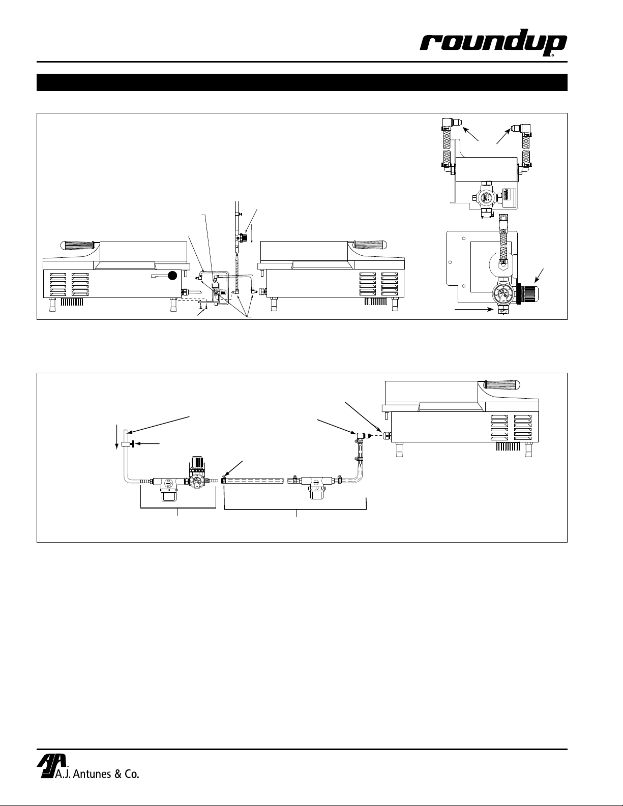
Installation...................................................................7
Unpacking..................................................................7
Equipment Setup.......................................................7
Water Pressure Regulator .........................................7
Drain ..........................................................................7
Electrical ....................................................................7
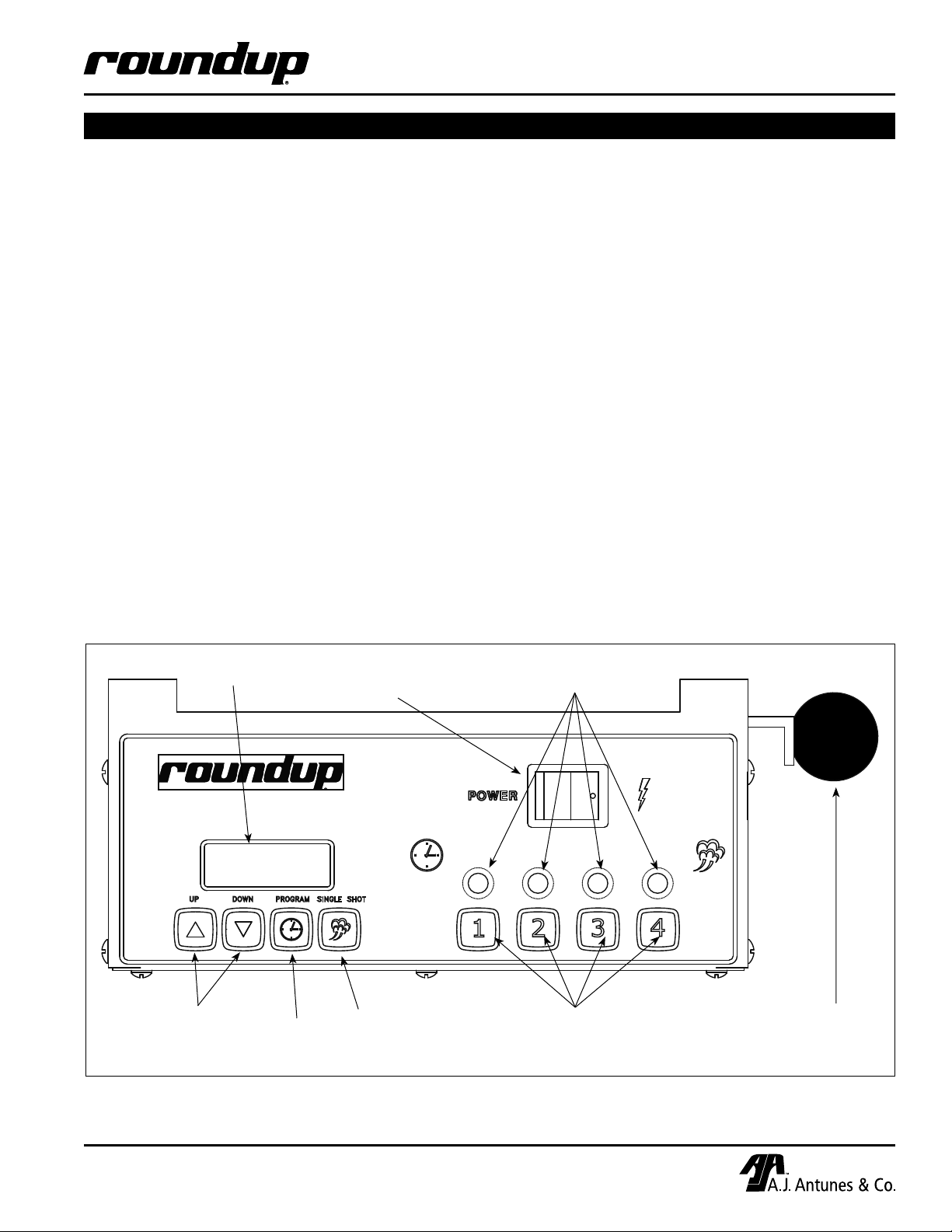
Operation.....................................................................9
Operator Controls......................................................9
Operating Instructions .............................................10
Programming ............................................................ 11
General Programming .............................................11
Factory Settings.......................................................11
Programming the Unit .............................................11
Maintenance..............................................................13
DailyCleaning .........................................................13
Monthly Cleaning.....................................................13
Diagnostics ..............................................................15
Technical Theory of Operation ................................17
Troubleshooting .......................................................18
Wiring Diagrams.......................................................20
Replacement Parts ...................................................21
Notes..........................................................................23
Limited Warranty ......................................Back Cover

3
VARIETY STEAMER (VS-250)
P/N 1010998 Rev. C 11/12
Service/Technical Assistance
If you experience any problems with the installation
or operation of your unit, contact your local Roundup
Authorized Service Agency. They can be found in the
service agency directory packaged with the equipment.
Fill in the information below and have it handy when
calling your Authorized Service Agency for assistance.
The serial number is on the specification plate located
on the rear of the unit.
Purchased From:
DateofPurchase:
Model No.:
Serial No.:
Mfg. No.:
Refer to the service agency directory and fill in the
information below:
Authorized Service Agency
Name:
Phone No.:
Address:
Use only genuine Roundup replacement parts in this
unit. Use of replacement parts other than those sup-
plied by the manufacturer will void the warranty. Your
Authorized Service Agency has been factory trained
and has a complete supply of parts for this unit.
You may also contact the factory at 1-877-392-7854
or 630-784-1000 if you have trouble locating an
Authorized Service Agency.
OWNER INFORMATION (continued)
IMPORTANT
A.J. Antunes & Co. reserves the right to change specifications and product design
without notice. Such revisions do NOT entitle the buyer to corresponding changes,
improvements, additions, or replacements for previously purchased equipment.

VARIETY STEAMER (VS-250)
4P/N 1010998 Rev. C 11/12
IMPORTANT SAFETY INFORMATION
In addition to the warnings and cautions in this manual,
use the following guidelines for safe operation of the
unit.
• Readallinstructionsbeforeusingequipment.
• Foryoursafety,theequipmentisfurnishedwith
aproperlygroundedcordconnector.DoNOT
attempt to defeat the grounded connector.
• Installorlocatetheequipmentonlyforitsintend-
eduseasdescribedinthismanual.DoNOTuse
corrosive chemicals in this equipment.
• DoNOToperatethisequipmentifithasadam-
aged cord or plug, if it is not working properly, or
if it has been damaged or dropped.
• Thisequipmentshouldbeservicedbyqualified
personnel only. Contact the nearest Authorized
Service Agency for adjustment or repair.
• DoNOTblockorcoveranyopeningsontheunit.
• DoNOTimmersecordorpluginwater.
• Keepcordawayfromheatedsurfaces.
• DoNOTallowthecordtohangoveredgeoftable
or counter.
The following warnings and cautions appear
throughout this manual and should be carefully
observed.
• Turnthepoweroff,unplugthepowercord,
and allow the unit to cool down before per-
forming any service or maintenance.
• Theproceduresinthischaptermayinclude
the use of chemical products. These chemi-
cal products will be highlighted with bold
face letters followed by the abbreviated HCS
(Hazard Communication Standard). See
Hazard Communication Standard manual for
the appropriate Material Safety Data Sheets
(MSDS).
• Theequipmentshouldbegroundedaccord-
ing to local electrical codes to prevent the
possibility of electrical shock. It requires a
grounded receptacle with separate electrical
lines, protected by fuses or circuit breaker of
the proper rating.
• Allelectricalconnectionsmustbeinaccor-
dance with local electrical codes and any
other applicable codes.

5
VARIETY STEAMER (VS-250)
P/N 1010998 Rev. C 11/12
• WARNING ELECTRICAL SHOCK HAZARD.
FAILURE TO FOLLOW THESE INSTRUCTIONS
COULD RESULT IN SERIOUS INJURY OR
DEATH.
- Electrical ground is required on this unit.
- Do NOT modify the power supply cord
plug. If it does not fit the outlet, have a
proper outlet installed by a qualified
electrician.
- Do NOT use an extension cord with this
unit.
- Check with a qualified electrician if you
are unsure if the appliance is properly
grounded.
• Ifthesupplycordisdamaged,itmustbe
replaced by the manufacturer, its service
agent, or a similarly qualified person.
• Thisequipmentistobeinstalledtocom-
ply with the basic plumbing code of the
Building Officials and Code Administrators,
Inc. (BOCA) and the Food Service Sanitation
Manual of the Food and Drug Administration
(FDA).
• Waterpressuremustnotexceed30psi(2.1
kg/cm2or 207 kPa). Higher water pressures
may cause poor performance or flooding.
To reduce water pressure, install a Water
Pressure Regulator and set to 20–25 psi
(1.4–1.7 kg/cm2or 138–172 kPa).
• DoNOTcleanthisappliancewithawaterjet.
• DoNOTuseasanitizingsolutionorabrasive
materials. The use of these may cause dam-
age to the stainless steel finish.
• Toensurepropersteamingcharacteristics,
some calcium/mineral deposits must be pres-
ent on the Generator Surface. If, during clean-
ing, the surface does become free of deposits,
add plain tap water to the surface and allow it
to boil off. This will ensure proper steaming
characteristics by creating a thin layer of cal-
cium/mineral deposits.
• Chlorides or phosphates in cleaning agents
(e.g. bleach, sanitizers, degreasers, or deter-
gents) could cause permanent damage to
stainless steel equipment. The damage is
usually in the form of discoloration, dulling
of metal surface finish, pits, voids, holes, or
cracks. This damage is permanent and NOT
covered by warranty.
The following tips are recommended for main-
tenance of your stainless steel equipment:
- Always use a soft, damp cloth for cleaning,
rinse with clear water, and wipe dry. When
required, always rub in direction of metal
polish lines.
- Routine cleaning should be done daily
using soap, ammonia detergent, and water.
- Stains and spots should be removed using
a vinegar solution.
- Finger marks and smears should be
rubbed off using soap and water.
- Hard water spots should be removed using
a vinegar solution.
IMPORTANT SAFETY INFORMATION (continued)

VARIETY STEAMER (VS-250)
6P/N 1010998 Rev. C 11/12
SPECIFICATIONS
Electrical Ratings
Shipping Weight
63 lbs. (28 kg)
Electrical Cord & Plug Configurations
CAUTION
All electrical connections must be in accordance
with local electrical codes and any other appli-
cable codes.
WARNING
ELECTRICAL SHOCK HAZARD.
FAILURE TO FOLLOW THE INSTRUCTIONS IN
THIS MANUAL COULD RESULT IN SERIOUS
INJURY OR DEATH.
• Electricalgroundisrequiredonthisappliance.
• DoNOTmodifythepowersupplycordplug.If
it does not fit the outlet, have a proper outlet
installed by a qualified electrician.
• DoNOTuseanextensioncordwiththisunit.
• Checkwithaqualifiedelectricianifyouare
unsure if the appliance is properly grounded.
Dimensions
Model &
Mfg. No. Description Configuration
VS-250
9100260 &
9100261
6 - 2 0 P,
20 Amp.,
250 VAC
VS-250
9100262
Intl. Plug,
16 Amp.,
250 VAC CAUTION
This equipment is to be installed to comply with
the basic plumbing code of the Building Officials
and Code Administrators, Inc. (BOCA) and the
Food Service Sanitation Manual of the Food and
Drug Administration (FDA).
Model &
Mfg No. Voltage Watts Amps Hertz
VS-250
9100260 &
9100261
208 2854 13.7 50/60
VS-250
9100262 230 3489 15.2 50/60

7
VARIETY STEAMER (VS-250)
P/N 1010998 Rev. C 11/12
Unpacking
1. Remove unit and all packing materials from
shipping carton.
2. The unit should contain the following:
• Owner’sManual
• AuthorizedServiceAgencyDirectory
• PetroGelTube
• InletHoseandStrainerAssembly
• BlackDrainTubing
NOTE: If any parts are missing or damaged,
contact Antunes Technical Service IMMEDIATELY
at 1-877-392-7854 or 630-784-1000.
3. Remove all packing materials and protective
coverings from the unit.
4. Remove and wash all removable parts in soap
and water. Rinse with clean hot water and allow
to air dry.
NOTE: The Generator surface (Figure 8) will have
a thin white coating of artificial lime deposits.
This coating is necessary for steaming character-
istics and should NOT be removed. Refer to the
Maintenance section of this manual for more
information.
5. Wipe all surfaces of the unit with a hot damp
cloth.
NOTE: Do NOT use a dripping wet cloth. Wring
out before use.
6. Re-install all removed parts.
Equipment Setup
GENERAL
When placing the unit into service, pay attention to
the safety guidelines listed in the Important Safety
Information section of this manual.
PLUMBING
NOTE: Variety Steamer models are designed to
use cold tap water at 20–25 psi (1.4–1.7 kg/cm2or
138–172 kPa).
Your VS-250 requires a direct water hookup. An Inlet
HoseandStrainerAssembly(Figure2Aand2B)is
supplied with the unit. A Water Pressure Regulator
(P/N 7000235 to feed two steamers or P/N 7000314 to
feed one steamer) must first be installed.
INSTALLATION
Water Pressure Regulator
1. Install the regulator assembly to the steamer as
shown in Figure 2A and 2B.
2. Open the shut off valve to allow water flow to
the regulator. Ensure that the Water Pressure
Regulator is set at 20–25 psi. If not, adjust the
regulator by pulling softly on the knob and turning
until the gauge reads the desired pressure. Push
in the knob to lock.
NOTE:Ifthepressurewasadjusted,theexisting
pressure must be relieved in order to register the
new set pressure.
3. Push the white plastic tip on each 1/4” Elbow
QuickDisconnect(Figure2Aand2B)andhold
for a few seconds to purge out air in the line and
allow water to flow freely into a bucket with a
steady stream.
4. Pusheach1/4”ElbowQuickDisconnectintothe
rear of the steamer until a click is heard. Turn on
the steamer and allow 20 minutes to warm up.
Cycle the unit three times and check the pressure
regulator setting. If there is a change, adjust it
again to read 20–25 psi and then push the knob
in to lock. The unit is ready for use.
Drain
ConnecttheBlackDrainTubing(Figure8)totheDrip
Tray by pressing the tubing onto the drain pipe at the
bottomoftheDripTray.Placetheotherendofthe
tubing in a drain or collection pan.
Electrical
1. Place the unit on a sturdy, level table or other
work surface. Be sure the power is off before
proceeding.
2. Connect the unit to the power supply.
CAUTION
Water pressure must not exceed 30 psi (2.1
kg/cm2or 207 kPa). Higher water pressures
may cause poor performance or flooding. To
reduce water pressure, install a Water Pressure
Regulator, and set water pressure to 20–25 psi
(1.4–1.7 kg/cm2or 138–172 kPa).

VARIETY STEAMER (VS-250)
8P/N 1010998 Rev. C 11/12
Tubing - 1/4" ID PVC (2)
Manifold/Regulator
Assembly
#8 Bracket Screws (3) Elbow, Quick Disconnect - 1/4" (3)
Cold
Water
Flow
Shut Off Valve (not supplied) Inlet Hose & Strainer Assy. (supplied)
Figure 2A. Connecting Dual Manifold Water Pressure Regulator (P/N 7000235)
!WARNING 18
MISUSE OF PRODUCTMAY CAUSE
PERSONALINJURY.READ ASME
INSTALATION/OPERATING INTRUCT
MADE IN USA IMI
R91G-24K-NLN
INLET 150 PSIG MAX
OUTLET 125 PSIGMAX
To
Steamers
Pressure
Adjustment
knob
Inlet Water
Supply
Connect Quick
Disconnect
Insert Here
Inlet Hose & Strainer
Assy. (Supplied)
Water Pressure Regulator
& Strainer Assy. (P/N 7000314) Shown
Shut Off Valve
(Not Supplied)
Cold
Water
Flow
Flexible Nylon Braided
1/4 " I.D. Tubing (Not Supplied) Elbow Quick
Disconnect
Worm
Clamp
Figure 2B. Connecting Single Water Pressure Regulator
INSTALLATION

9
VARIETY STEAMER (VS-250)
P/N 1010998 Rev. C 11/12
OPERATION
Figure 3. Operator Controls
TIMED CYCLE
The desired timed steaming cycle (up to 99 minutes
and 59 seconds) is selected by pressing and releas-
ing any of the four menu buttons (Figure 3). The main
Control Board applies power to the solenoid at regular
intervals for the duration of the displayed cycle time.
The display counts down to zero when the cycle is
complete, then reverts back to the original programmed
cycle time and the unit is ready for the next cycle.
IMPORTANT: Your steamer is factory programmed
for the following (on each of the 4 menu channels):
• TotalCycleTime=10seconds[00:10]
(Range: 1 second to 99 minutes and 59 seconds)
• ShotIntervalRate(RATE)=5seconds[00:05]
(Range: 1 second to 5 minutes and 59 seconds)
• SteamShotTime(SHOT)=0.70 second [00:70]
(Range: 0.10 second to 2.50 seconds)
This converts approximately 3/4 oz. (25 milliliters)
of water to steam every 5 seconds for a 10 second
steaming cycle. To change any of these settings refer
to the Programming section of this manual.
Operator Controls
POWER SWITCH
When the Power Switch is on, the Control Board
is activated. If the Generator temperature is below
the factory preset setpoint, power is applied to the
Generator until the setpoint temperature is reached.
The Generator is constantly monitored and power is
regulated to maintain the temperature setpoint.
MENU BUTTONS
When any menu button is pressed and released,
power is supplied to the solenoid, the solenoid oper-
ates, and water sprays onto the heated Generator sur-
face. The water flashes immediately into live steam to
heat the product.
One of two operational modes can be used: Single
Shot or Timed Cycle
SINGLE SHOT
The SINGLE SHOT button (Figure 3) is pressed and
released to initiate a single shot. The Control Board
applies power to the solenoid and a single shot of
steam occurs.
Display Window
Program
Button
Single Shot
Button
Up and Down
Arrow Buttons
Power Switch
Menu Channel Buttons Lock Lever
Menu Channel Indicator Lights

VARIETY STEAMER (VS-250)
10 P/N 1010998 Rev. C 11/12
Operating Instructions
1. Turn the unit on and allow it to preheat for approx-
imately 30 minutes.
IMPORTANT: Do NOT push any of the MENU
CHANNEL buttons during warm-up. The word
“LOW” flashes on the display to indicate the unit is
not up to operating temperature. When the cycle
time is displayed, the unit may be operated.
2. Remove baskets and place the desired product
into baskets. Insert baskets into the steamer.
3. Single Shot: Press and release the SINGLE
SHOT button and wait 10 seconds for the steam
to penetrate the product.
Timed Cycle: Momentarily pressing any one of
the four MENU CHANNEL buttons will begin a
steamingcycle.Duringthecycle,thedisplaywill
count down to zero, with an audible tone to signal
the completion of the cycle.
NOTE: Experiment by steaming product at differ-
ent settings until correct cycle for that product is
found.
4. When the cycle is complete, remove and empty
the basket(s). At the end of the serving day or
shift, turn off the unit and allow it to cool before
performing the daily Cleaning procedures in the
Maintenance section of this manual.
UP & DOWN ARROW BUTTONS
The actual Generator temperature can be viewed by
depressing the UP ARROW button (Figure 3) at any
time. The arrow buttons are used with the other buttons
to program the unit (see the Programming section of
this manual for more information).
LOCK LEVER
When in the full forward (towards operator) posi-
tion, the Lock Lever (Figure 3) secures the Generator
Manifold in position on top of the unit. Moving the
Lock Lever to the full rearward position unlocks the
Generator Manifold, allowing it to be removed for
cleaning or servicing.
NOTE: Do NOT force the lever into position.
HI-LIMIT RESET THERMOSTAT
IftheGeneratoroverheatsforanyreason,theHi-Limit
Thermostat cuts off power to the Generator. This can
be reset by turning the unit off, unplugging the power
cord, and allowing the unit to cool for 45 minutes.
RemovetheBasketsandBasketHousing.Fliptheunit
overandcarefullyremovetheFrontControlHousing.
ThenpresstheHi-Limit’sredresetbutton(Figure8).If
theHi-LimitThermostatrequirescontinuousresetting,
contact your Authorized Service Agency
WARNING
Toavoidinjury,becarefulwhenpullingbasket
assembly out from unit. Be sure to allow steam
to escape before putting hands or face over the
steamer.
OPERATION (continued)

11
VARIETY STEAMER (VS-250)
P/N 1010998 Rev. C 11/12
General Programming
CYC (Total Cycle Time) refers to the total amount of
cooking time set for the product (Figure 4).
RATE (Shot Interval Time) is the time set between
each shot of steam during a complete cycle (Figure 5).
PROGRAMMING
400F
To verify or change the Generator setpoint tempera-
ture, press and hold the UP and DOWN ARROW but-
tons simultaneously for three seconds. Then, raise or
lower the temperature by depressing the UP or DOWN
ARROW buttons. Release the buttons when the
desired temperature is reached.
15:00
To Change the display from Fahrenheit (F) to
Celsius (C), press and hold the UP ARROW and the
PROGRAM buttons simultaneously for three seconds.
Repeat the process to reverse.
15:00
To verify the actual Generator temperature, press and
hold the UP ARROW button. The unit will display the
actual Generator temperature.
Before starting initial programming, there are three
items that should be verified.
* Check/change the setpoint temperature of the
generator (it is recommended that the generator be
set at 375°F (191°C).
* Change the display from Fahrenheit (F) to Celsius
(C) or vice versa.
* Verify the generator temperature after a 30 minute
pre-heat time.
Listed below are the steps to follow for the recommen-
dations listed above.
SHOT (Steam Shot Time) is used to adjust the water
volume used during each solenoid operation (shot of
steam) (Figure 6).
The amount of steam produced by your unit depends
on the amount of water sprayed onto the Generator sur-
face.FloodingoftheGeneratormayoccuriftheSHOT
setting is too high or if the RATE setting is too low.
To prevent this from occurring, the RATE should be
increased to allow more time for Generator heat recov-
ery,andtheSHOTcanbedecreasedtoreducethe
water volume.
Adjustments should be made to both values to deter-
mine the optimum settings for your cooking needs.
Factory Settings
The VS-250 is factory programmed for the following
values for each of the 4 menu channels:
CYC=[00:10]10seconds
(Range: 1 second to 99 minutes 59 seconds)
RATE=[00:05]5seconds(recommended)
(Range: 1 second to 5 minutes 59 seconds)
SHOT=[00:70]0.70seconds(recommended)
(Range: 0.10 second to 2.50 seconds)
These settings deliver approximately 3/4 oz. (25 millili-
ters) of water every 5 seconds for a 10-second cooking
time. Changes may be made to any of these settings.
However,foroptimumperformance,thesettingsshould
remain as shown above.
To restore the factory settings:
1. Turn the unit off. Press and hold the PROGRAM
and SINGLE SHOT buttons.
2. Continue to hold these buttons while turning the
unit on.
3. Release the buttons once the unit stops beeping.
Programming the Unit
NOTE: CYC, RATE, and SHOT are sequential
operations per channel for all programming (you
must perform all steps for CYC and RATE to change
SHOT).
NOTE: CYC, RATE, and SHOT are only displayed
momentarily during the programming sequence
when the PROGRAM button is pressed.

VARIETY STEAMER (VS-250)
12 P/N 1010998 Rev. C 11/12
12 3 4
SHOT
Figure 6. SHOT Mode on Menu 1
CYC (Total Cycle Time)
1. Turn the power on and allow the unit to preheat
for 30 minutes.
NOTE: During preheating, the display will flash
“LOW”. When unit reaches operating temperature,
the display shows the factory preprogrammed
(default) time in minutes/seconds (Figure 7) and the
active channel indicator light will be on.
2. Press the PROGRAM button to change the con-
trol from Operation to Program mode. “CYC”
will appear in the display for a moment. Select
a Menu Channel (1 thru 4), making the selected
channel the active channel.
NOTE: If no change is made within 10 seconds
at any time during the programming process, all
changes made up to that point are stored in memo-
ry and the control reverts to Operation mode.
3. Press the UP or DOWN ARROW buttons to
change the total cycle time in minutes (Figure 7).
4. Press the PROGRAM button again, then use the
UP or DOWN ARROW buttons to change the
total cycle time in seconds.
5. When finished, either:
a.) Press the selected MENU CHANNEL button
to store the changes; pressing this again will start
the steam cycle.
OR
b.) Select another menu channel for change and
repeat steps 3 & 4. Changes made to previous
channels will automatically be stored.
12 3 4
RATE
Figure 5. RATE Mode on Menu 1
12 3 4
CYC
Figure 4. CYC Mode on Menu 1
RATE (Shot Interval Time)
6. While in Program mode (press the PROGRAM
button if not in this mode), press both the UP and
DOWN ARROW buttons simultaneously. “RATE”
will appear in the display for a moment (Figure 5).
7. Use the UP or DOWN ARROW buttons to
change the RATE setting in seconds.
8. Press the PROGRAM button again, then use the
UP or DOWN ARROW buttons to change the rate
time in minutes.
SHOT (Steam Shot Time)
9. Press the PROGRAMbuttonagainand“SHOT”
will appear in the display for a moment (Figure 6).
10. Use the UP or DOWN ARROW buttons to
increase or decrease the time.
11. Press the selected channel button to store the
changes (Figure 6) or press another channel
button to store the changes and select a new
channel.
12. Repeat steps 1 through 11 for any of the other
menu channels.
NOTE: The SINGLE SHOT button may be pressed
at anytime during programming to store any
changes made and execute a fixed single shot of
0.70 second.
Figure 7. Changing Total Cycle Time
12 3 4
00:10
Minutes Seconds
PROGRAMMING (continued)

13
VARIETY STEAMER (VS-250)
P/N 1010998 Rev. C 11/12
4. Lift and slide the Locking Lever (Figure 8)
towards the rear, and then carefully remove the
Black Manifold Plate. Then remove the large
black O-ring from the plate.
5. RemovetheDiffuserPlate.Thenremovethe
Spray Tube by carefully lifting the loose end and
gently twisting and pulling it out of the Steam
Generator hole.
6. Take a suitable 1/16” punching tool (such as a
paperclip) and insert it through all 18 orifices
in the Black Manifold and the 10 orifices in
the Spray Tube to assure the orifices are not
obstructed with debris. Wash all items in hot,
soapy water, rinse, and then allow to air dry.
7. Reinstall the Spray Tube into the Steam
GeneratorholeandreinstalltheDiffuserPlate.
8. Lightly apply some Petrol Gel (included) onto the
O-ring and reinstall the O-ring onto the Manifold
Plate (this allows the Manifold Plate to seat easily
onto the Steam Generator).
9. HoldtheManifoldPlateuptoalightsourceand
verify that light is visible through all the orifices. If
so, seat the manifold fully onto the Generator and
pull the Locking Lever forward to lock the plate.
10. Check that the Water Pressure Regulator is
correctly set to 20 psi (1.4 kg/cm2or 138 kPa).
11. Reinstall all parts and accessories.
MAINTENANCE
Daily Cleaning
NOTE: Frequency of cleaning is determined by
water conditions, usage, and water filter systems.
1. Turn the power off, unplug the power cord, and
allow the unit to cool for 30 minutes.
2. Check the rear water quick disconnect fitting and
all hose clamp connections for leakage. If leak-
age is apparent, tighten all clamps or replace
part(s) if required.
3. Remove the Baskets, Top Cover Assembly, and
DripTray(Figure8).Washinhot,soapywater,
then rinse and allow them to air dry.
CAUTION
Do NOT use a sanitizing solution or abrasive
materials. The use of these may cause damage to
the stainless steel finish.
CAUTION
Failure to regularly and/or properly clean this
equipment may damage it or cause the user
bodilyinjury.
WARNING
Refer to the instructions for cleaning and handling
the unit within the Important Safety Information
section of this manual.
Figure 8. Steamer Components & Accessories
O-ring Diffuser
Spray Tube
Black Manifold
Plate
Drip Tray
Lock
Lever
Top Cover Assy.
Double
Baskets
Steam
Generator
Black
Drain
Tubing
Inlet Hose Assy.
(w/ Strainer) Hi-Limit Thermostat
(inside unit)
Electrical
Housing
Cover
Pressure Relief
Plunger Assy.

VARIETY STEAMER (VS-250)
14 P/N 1010998 Rev. C 11/12
Monthly Cleaning
CLEANING THE STEAM GENERATOR
Your steamer utilizes an open Steam Generator. Water
sprayed onto the Generator surface flashes into steam
immediately, but the minerals in the water stay on the
Generator surface. A small amount of calcium/min-
eral deposits are needed for proper operation, but a
buildup of excessive calcium/mineral deposits causes
poor steaming efficiency and excessive moisture (wet
steam), which will eventually affect the steaming action
completely.
1. Turn the power off, unplug the power cord, and
allow the unit to cool down before proceeding.
2. PerformtheDailyCleaningprocedures,butdo
NOT reassemble the unit.
3. With the unit cool, use a non-abrasive brass
brush and/or scraper to loosen and remove
the excessive calcium/mineral deposits from
the Generator surface (Figure 8). Wipe the
Generator with a clean damp cloth. Reassemble
the unit.
NOTE: If deposits are still excessive and/or
difficult to remove, see Step 4.
4. Wearing protective eyewear and gloves, pour
delimer solution (not supplied) onto the Generator
surface (Figure 8). Be sure to follow the delimer
manufacturer’s directions for proper mixture and
use.
5. Using a sponge or dry towel, remove the delimer
solution from the Generator. Then, rinse the
Generator with clear water.
CAUTION
If a chemical cleaner/delimer is used, be sure it is
safe to use on cast aluminum. Observe all pre-
cautions and warnings on the product label.
NOTE: To ensure proper steaming characteristics,
some calcium/mineral deposits must be present on
the Generator surface. If, during cleaning, the sur-
face does become free of calcium/mineral depos-
its, add plain tap water to the surface and allow it
to boil off. This may have to be repeated several
times in order to formulate a thin coating of depos-
its. If unsuccessful, see below.
NOTE: In soft water areas, it may be necessary to
add a small amount of lime to the Generator sur-
face to season it. This will ensure proper steam-
ing characteristics by producing a thin coating of
calcium/mineral deposits on the Generator sur-
face. Seasoning mixture consists of 3/4 ounces
(25ml/25cc) of baking soda, 3/4 ounces (25ml/25cc)
of lime and 1 quart (950ml/950cc) of water. Stir
mixture and pour 1/4” deep onto the hot Generator.
After mixture is converted to steam, the remaining
loose powder can be wiped off.
6. Plug power cord into electrical outlet
7. Turn power on and allow the unit 30 minutes to
warm up.
8. Press the SINGLE SHOT button three times to
purge remaining delimer from the Generator.
MAINTENANCE (continued)

15
VARIETY STEAMER (VS-250)
P/N 1010998 Rev. C 11/12
Diagnostics
The four-channel controller is also equipped with diag-
nostic features. Listed under each drawing is a brief
description of the particular feature. Also contained in
the control housing mounted on the control board are
diagnosticLED’s.Theyareinthreecolorsandrepre-
sent the following:
*Green (Program): When lit, indicates factory
settings are being set.
* Yellow (Audio):Whenlit,indicates10-15VDC
is being supplied to the audio signal. The Audio
Signal will sound for 3 seconds.
* Red (Heat): When lit, indicates the unit is calling
forheatbysupplying3-5VDCtotheSolidState
Relay. When off, it indicates the heating circuit is
satisfied.
* Green (Water): When lit, indicates that 24 VAC is
is being supplied to open the Solenoid.
NOTE: This LED is only lit for approximately one
second.
HIGH will be displayed when the Generator tempera-
ture exceeds the setpoint temperature by 50°F (10°C).
HIGH
CHECKING AND CLEANING THE WATER STRAINER
The Water Strainer protects the unit from any foreign
debris in the water line that could get into the food,
damage the unit’s solenoid (causing the unit to leak or
flood), or interfere with the equipment’s proper and con-
sistent operation (Figure 10).
To ensure proper and consistent steaming results,
check the Water Pressure Regulator and Strainer
Cup regularly. If the pressure on the Water Pressure
Regulator has dropped, check the clear plastic Strainer
Cup and clean out the accumulated debris.
1. Shut off the water supply valve to the unit,
unscrew the plastic Strainer Cup, and carefully
remove the mesh Strainer Screen.
2. Take the Strainer Cup and Strainer Screen to
the sink and gently flush out all the accumulated
debris. Be especially careful not to damage the
Strainer Screen.
3. Carefully place the Strainer Screen into its seat at
the bottom of the Strainer Cup and confirm that
the orange O-ring is properly seated in its place
before screwing the Strainer Cup and top back
together.
4. Purge the air out of the strainer and tubing by dis-
connecting the male quick disconnect fitting from
the equipment and, over a bucket, pushing the
white plastic tip in until there is a good water flow.
5. Replace damaged or worn parts as needed.
Item Part Description Qty.
No.
1 7000333 WaterLineStrainerKit 1
2 2040130 Male Adapter, Barbed - 1/4” 2
3 7000334 ReplacementScreenandO-ringKit 1
4 2110104 Clamp, Worm (not shown) 2
1/4
NPT
22
3
NOTE: Item 1 is made up of
shown items 2-4.
Figure 10. Water Line Strainer Kit
MAINTENANCE (continued)

VARIETY STEAMER (VS-250)
16 P/N 1010998 Rev. C 11/12
“PWR” will be displayed when the supply voltage is lower
than 160 Volts AC or above 265 Volts AC.
PWR
“OPEN” will be displayed when the thermocouple is open or
not installed correctly. The unit will not call for heat.
OPEN
“TEMP” indicates the control cabinet temperature has
exceeded 155°F (68°C) causing the unit to shut down. If this
occurs, the unit must be turned off for at least 20 minutes so
it can cool off and reset. If this condition occurs again, con-
tact your maintenance person or Authorized Service Agency.
The Control Board monitors the control cabinet ambient tem-
perature and records the highest temperature. Your
service technician could find such information very useful
when troubleshooting the unit.
To determine the control cabinet’s highest temerature since
the last reset:
1. Turn the unit off.
2. Turn the unit back on while pressing both the UP and
DOWN ARROW buttons at the same time.
3. Read the highest control cabinet temperature shown
on the display and release the arrow buttons.
4. Turn the unit off again to preserve this record.
To clear/reset this record, press both the UP and DOWN
ARROW buttons simultaneously (before turning the unit off)
and the display will show 33°F—indicating that record has
been cleared—and then turn the unit off.
TEMP
“LOW”will be displayed until the Generator temperature
exceeds 250°F (121°C).
LOW
“ERR”will be displayed if there is a programming parameters
error. If this message appears, you will have to clear the
current parameters. To clear the unit’s current programming
and reset the unit to its factory settings:
1. Turn the unit off.
2. Press and hold the SINGLE SHOT and PROGRAM
buttons simultaneously and continue to hold them while
turning the unit back on until you hear the beep stop.
3. Check the display:
• IftheDisplayshows“ERR”again,repeatsteps1
through 2. If “ERR” still appears on the display,
contact your maintenance person or Authorized
Service Agency.
• IftheDisplayappearsnormal,tryasingleshot
before attempting to reprogram the unit.
Review the Programming section of this manual and then
program the Menu Channel buttons according to your
cooking requirements.
ERR
MAINTENANCE (continued)

17
VARIETY STEAMER (VS-250)
P/N 1010998 Rev. C 11/12
Technical Theory of Operation
When the Power Switch is on, line voltage flows to the
primary side of the step down transformer. The trans-
former’s secondary side supplies 12 and 24 VAC to the
Control Board.
Once powered, and provided that the Generator’s tem-
perature is below the setpoint temperature, the Control
Boardcallsforheatbysupplying3to5VDCtothe
Solid State Relay terminals 3 (+) 4 (-). Once powered,
the Solid State Relay then closes terminals 1 and 2,
which allows line voltage to flow to the Generator.
AstheGeneratorbeginstoheatup,atype“K”thermo-
couple monitors the internal Generator temperature.
As the heat continues to increase, so does the thermo-
couple’sDCmillivolts.
Once the Generator’s temperature approaches the
setpoint temperature, the Control Board begins to pulse
theVDCtotheSolidStateRelay.TheGenerator’s
VAC and AMPS will also pulse during this point. When
the Generator’s temperature is between the recom-
mended setpoints of 375°F─400°F (190°C─204°C), the
thermocouple generates approximately 7.5─8.5DCmil-
livolts. The Control Board receives these millivolts and
proceeds to remove the 3─5VDCtotheSolidState
Relay since the heating circuit has now become satis-
fied.
Then, the Solid State Relay terminals 1 and 2 open up,
and the Generator stops heating. The heating circuit
cycles on and off as needed, even at idle.
When the SINGLE SHOT button is pushed, it signals
the Control Board to initiate a single shot of steam. The
Control Board then supplies 24 VAC to the Solenoid
Valve for a split second. The Solenoid Valve opens and
allows approximately 3/4─1 ounce (4 to 5 tablespoons)
of water to be disbursed onto the Generator surface
for steaming. The water is immediately converted into
steam, which is forced up through the Black Manifold
Orifices to steam the product within the baskets.
Each of the four MENU CHANNEL buttons can be
custom programmed for cycle time, time between when
each steam shot occurs, and water volume used per
each shot (See the Programming section of this manu-
al). An audio signal will sound for three seconds at the
end of the cycle.
If the heating circuit continues to call for heat and the
Generatoroverheats,amanualresettableHi-Limit
Thermostat will trip and open the Generator circuit.
NOTE: If any of these conditions should arise, the
root cause must be determined and corrected. See
the Maintenance section of this manual for further
details.
NOTE: All direct water feed units require a Water
Pressure Regulator. It should be set to 20─25 psi
(1.4─1.7 kg/cm2or 138─172 kPa). Failure to install
a Water Pressure Regulator will result in poor
steaming and flooding of the steam generator.
MAINTENANCE (continued)

VARIETY STEAMER (VS-250)
18 P/N 1010998 Rev. C 11/12
TROUBLESHOOTING
WARNING
Toavoidpossiblepersonalinjuryand/ordamagetotheunit,inspection,test,andrepairofelectricalequip-
ment should be performed by qualified service personnel. The unit should be unplugged when servicing,
except when electrical tests are required.
Problem Possible Cause Corrective Action
Power is turned on but
the Switch Indicator Light
is still off and the Control
Panel is blank.
Power cord not correctly plugged in. Plug in the power cord correctly.
The power cord and/or electrical plug
is damaged.
Inspect electrical wire, plug, and receptacle.
The main electrical panel circuit
breaker is off or has been tripped.
Reset circuit breaker. Contact your mainte-
nance person or Authorized Service Agency if
it trips again.
Power Switch is inoperable. Contact your maintenance person or
Authorized Service Agency for service.
The unit’s main electri-
cal panel circuit breaker
trips.
Damagedreceptacle,plug,orcord;a
loose connection or an internal compo-
nent failure.
Turn the unit off, allow it to cool to room
temperature, and then restart the unit.
Power is turned on,
Switch Indicator Light on,
but the display is blank.
Control Board is inoperable. Contact your maintenance person or
Authorized Service Agency for service.
Transformer is inoperable.
Loose or burnt wiring in heating circuit.
Power is turned on,
Switch Indicator Light
is on, the Control Panel
is on, but the unit is not
heating up.
HeatRelayisinoperable. ResettheHi-LimitThermostataccordingto
the Operations section of this manual. If the
Hi-LimitThermostatrequirescontinuousreset-
ting, contact your maintenance person or
Authorized Service Agency for service.
Hi-LimitThermostatistripped.
Thermocouple is inoperable.
Control Board is inoperable.
Steam Generator is inoperable.
Loose or burnt wiring in heating circuit.
Unit heats but there is
little or no steam
produced
and/or
The product requires
more steaming than
usual.
Water Line Valve is closed. Check that the Water Line Valve is open.
Filter Strainer is restricted. Check and clean the Filter Strainer as
described in the Maintenance section of this
manual.
QuickDisconnectisnotfullyengaged
at rear of the unit or is damaged.
RemoveandreengagetheQuickDisconnect
firmly until a click is heard. Replace if dam-
aged.
Low or no water pressure in water line. RemovetheQuickDisconnectInsertfromthe
rear of the unit. While holding into an empty
cup, press the white plastic tip. Strong steady
water flow should be noted. If so, re-engage
firmly into unit. If not present, or pressure
is low, contact your maintenance person or
plumber.
Spray Tube is restricted. Remove and clean Spray Tube as described
in the Maintenance section of this manual.
Black Manifold orifices are restricted. Remove and clean the Black Manifold as
described in the Maintenance section of this
manual.
Unit is not being cleaned daily or
properly.
Clean unit daily as described in the
Maintenance section of this manual.

19
VARIETY STEAMER (VS-250)
P/N 1010998 Rev. C 11/12
TROUBLESHOOTING (continued)
Problem Prossible Cause Corrective Action
Unit heats but there is little or no
steam produced
and/or
The product requires more
steaming than usual (continued).
Improper water pressure to unit. Verify that a Water Pressure Regulator
is installed and set to 20─25 psi.
Insufficient or excessive calcium/min-
eral buildup on Generator
surface.
Verify that a thin layer of deposits is
present on the Generator surface.
Refer to the Maintenance section of this
manual.
Channels, or Rate and Shot values
were programmed improperly.
Restore programming to original values
as described in the Programming sec-
tion of this manual and then reprogram
as needed.
Black Manifold O-ring is damaged or
missing.
Install Manifold O-ring if missing.
Replace if it is damaged.
Low Generator setpoint temperature. Verify the setpoint temperature is
375°F─400°F (190°C─204° C).
Steam leaks out of the sides of
the Black Manifold Plate.
Black Manifold O-ring is damaged or
missing.
Install Manifold O-ring if missing.
Replace if it is damaged.
Black Manifold is difficult to lock
and unlock onto the Generator
with the Locking Lever.
Black Manifold not being removed
and cleaned daily as required.
Remove and clean the Black Manifold
daily as described in the Maintenance
section of this manual.
Black Manifold O-ring is damaged or
worn.
Replace Black Manifold O-ring if
damaged or worn.
Black Manifold O-ring is not being
lubricated daily with Petro gel.
Lubricate the Black Manifold O-ring daily
as described in the Maintenance section
of this manual.
Generator is dirty. Clean or delime the Generator. See the
Maintenance section of this manual for
more information.
Unit floods overnight and/or
continues to steam even when in
idle mode.
Solenoid Valve is being held open by
debris from the building’s water line
piping due to no pre-strainer/filter on
the water line just before the unit.
Attempt to flush the debris out of the
valve by rapidly operating the unit on a
number of Single Shot cycles and then
letting the unit rest. If the unit still leaks,
contact your maintenance person or
Authorized Service Agency.
Unit is whistling during use. Unit is not being cleaned daily and/
or properly.
See the Maintenance section of this
manual.

VARIETY STEAMER (VS-250)
20 P/N 1010998 Rev. C 11/12
WIRING DIAGRAMS
NOTE: ALL WIRES TO BE 22 GA. TFE-200°C
UNLESS OTHERWISE SPECIFIED.
# 18 GA. AWM-105°C
16 GA. TFE-200°C
14 GA. TFE-200°C
FOR MFG. NO 9100262 ONLY
FOR MFG. NO 9100260 ONLY
This manual suits for next models
3
Table of contents
Other Roundup Kitchen Appliance manuals
Popular Kitchen Appliance manuals by other brands

PARADISE GRILLS
PARADISE GRILLS Professional Pizza Conversion Operator's manual

Tricity Bendix
Tricity Bendix U020006 SI 255 Operating and installation instructions

Presto
Presto PowerPop instructions

Westmark
Westmark STEINFIX Getting Started, Assembly and Recipes

Kitchen Living
Kitchen Living 42508-14 user guide

KHIND
KHIND JE300 instruction manual