Rovers North Land Rover Defender 90 Kit User manual

1
Bu ld ng Gu de for
Assembl ng Wood
Model K ts
ROVERS NORTH, INC. 1319 VT ROUTE 128, WESTFORD, VT 05494 USA www.roversnorth.com (802) 879-0032
LAND ROVER DEFENDER 90 KIT
WOOD MODEL PARTS
MADE IN
THE UK
RNGWK90
1
/
18th
SEMI
-
SCALE
REALISTIC DISPLAY
*Not suitable for children under 6 years
of age; assembly with adult supervision
recommended. *Models can be painted
or ept in the original wood patina as shown.
Wh le th s bu ld ng gu de
features the assembly of
RNGWK90, steps, t ps and
notes are appl cable to
every wood model k t.

2ROVERS NORTH, INC. 1319 VT ROUTE 128, WESTFORD, VT 05494 USA www.roversnorth.com (802) 879-0032
RNGWK90
DEFENDER 90 WOOD MODEL PARTS KIT
1
/
1
8th
SEMI
-
SCALE
REALISTIC DISPLAY
Recommended Tools
NOTE: A shoebox or conta ner(s) w th a top works
great for hold ng all the small parts. Th s s helpful
for not los ng parts.
Med um CA Super Glue
(Cyanoacrylate) net we ght,
20g. Ava lable at most hard-
ware stores nat onw de.
Na l Pol sh Remover
(Acetone), use n well vent lated
area - used to debond CA Super
Glue. Ava lable at most drug stores.
Model ng Kn fe
Typ cal model ng or hobby
kn fe works, best s an X-
Acto w th #11 blade as
shown.
Model ng, Hobby F les
Square and or flat d amond
type files work the best.
An emory board, na l file or
220 sandpaper wrapped
and glued around a small
match st ck
w ll also work.
Cutt ng mat or s m lar mater al to protect
surface underneath work ng area
Self-heal ng cutt ng mat or su table surface
to protect work tables from kn fe, file and
sand ng marks.
CASUPER GLUE
MEDIUM GEL
CYANOACRYLATE
90˚ Tr angle
Small 30˚, 60˚, 90˚ tr angle
for check ng surfaces
220-320 Gr t Sandpaper
Used for sand ng wood
surfaces smooth.
NOTE: Where
nd cated, apply
CA Super Glue
as shown w th
th s con.
Read before assembly
*Study the nstruct ons thoroughly before assembly.
*There are many small parts. * Assemble them carefully
referr ng to the photos n th s gu de. *It s h ghly recommended to
assemble each step n order exactly as shown.
WARNING: I recommend using a Super Glue GEL formula
- it stays put and doesn’t wic as easily as regular super
glue. Pay attention, you can glue your fingers together! Use in a well
ventilated area. If the odor bothers you, a small fan blowing on your
wor area helps.
In steps 9B-9I bu ld ng the wheels, you w ll need to glue parts that
requ re us ng super glue n t ght areas. Take your t me, be pat ent and
keep a d sposable cloth or heavy duty shop towel ava lable to w pe up
any excess n a hurry. Keep alert of where you glue and what you
handle that s st ll dry ng. If you accidentally glue your fingers together
- don’t try to force them apart, it will brea the s in before the bond -
see unstic ing remedy tip on page 10.

3
ROVERS NORTH, INC. 1319 VT ROUTE 128, WESTFORD, VT 05494 USA www.roversnorth.com (802) 879-0032 RNGWK90
DEFENDER 90 WOOD MODEL PARTS KIT
1
/
1
8th
SEMI
-
SCALE
REALISTIC DISPLAY
Locate Chass s Parts
Start the Defender 90 wood model k t bu ld by locat ng the
chass s parts as shown above.
- Chass s flat base x1
- Chass s s des x2
TIP: In step 3 (see page 5), you w ll need the small square
metal file (na l file, emory board or sandpaper) to remove
the brown laser cutt ng glue res due and prepare each p ece
for ease of fitment.
Introduct on
Welcome to the build guide for our wood model its.
Th s gu de s to be used n conjunct on w th each wood model
k t to help a first-t me or seasoned model bu lder. Follow ng
these deta led notes and photos w ll g ve you the knowledge
on how to work w th a laser cut wood model assembly
process and make bu ld ng a fun exper ence.
Th s k t requ res the use of sharp tools, sharp po nted
nstruments for fil ng and Super Glue that can st ck your
fingers together. Please read through the ent re bu lde gu de
and fam l ar ze yourself w th what s nvolved before start ng.
Whether you plan to make th s a parent and ch ld learn-
ng exper ence or want to bu ld th s yourself, I hope my
decades of model bu ld ng knowledge can help steer you
along. Happy Land Rover Model Bu ld ng!
Cheers,
Thompson Sm th
Art/Creat ve D rector, Rovers North
1
Chass s
Base
x1
Front
Front
Chass s
S des
x2

4ROVERS NORTH, INC. 1319 VT ROUTE 128, WESTFORD, VT 05494 USA www.roversnorth.com (802) 879-0032
RNGWK90
DEFENDER 90 WOOD MODEL PARTS KIT
1
/
1
8th
SEMI
-
SCALE
REALISTIC DISPLAY
Chass s Exhaust S de w th
a grey fin sh
Chass s Etched S de w th
brown burn marks
NOTE: Laser cutt ng and etch ng plywood produces
two s des, an “etched s de” and an “exhaust s de”.
As the laser cuts through the plywood, the glue
used n assembl ng the plywood burns and leaves
a sl ght st cky brown res due on the etched surface and s des
as shown on (2B). The back exhaust s de of the plywood
shows grey marks shown on (2A). On the etched s de, you w ll
see burned- n deta ls l ke door l nes, and body l nes.
NOTE: In these nstruct ons you w ll be alerted to etched side
facing out and have to make sure you are glu ng w th the
correct s de fac ng out.
Ma n Floor Preparat on
When assembl ng the chass s, I choose to have the exhaust
s de of the ma n chass s floor on the ns de of the model, so
the etched s de (2B) was on d splay at the bottom. (My n t al
reason was so you wouldn’t see the exhaust grey s de when
hold ng the fin shed product. In h nds ght, I guess t doesn’t
matter, as a true past Land Rover Defender owner l ke my-
self knows, they are prone to leak a l ttle b t of o l and
grease - maybe show ng the exhaust s de underneath
would be a pos t ve d splay attr bute, e ther way works).
Keep each chass s s de w th exhaust s de n.
You w ll not ce that n some areas that the brown glue
has been filed off n the above photos. Th s w ll help fac l tate
the assembly of the two chass s s de p eces n steps 3, 4.
2

5
ROVERS NORTH, INC. 1319 VT ROUTE 128, WESTFORD, VT 05494 USA www.roversnorth.com (802) 879-0032 RNGWK90
DEFENDER 90 WOOD MODEL PARTS KIT
1
/
1
8th
SEMI
-
SCALE
REALISTIC DISPLAY
F le chass s n areas as shown. Don’t take too
much off; you only remove the brown laser
res due. Test fit a chass s s de at a t me before
glu ng.
NOTE: Locat on of chass s front and
correct or entat on of chass s s des -
h gh part of s des goes towards front.
F le axle locat ng slots on chass s s des pr or
to assembly and glu ng to chass s floor.
F le axle locat ng slots on chass s floor pr or to
assembly and glu ng of chass s s des.
Front
Assemble chass s s des. Make sure
each s de s fit t ght and all the way n
aga nst the chass s floor. Glue both
s des as marked.

6ROVERS NORTH, INC. 1319 VT ROUTE 128, WESTFORD, VT 05494 USA www.roversnorth.com (802) 879-0032
RNGWK90
DEFENDER 90 WOOD MODEL PARTS KIT
1
/
1
8th
SEMI
-
SCALE
REALISTIC DISPLAY
Locate front and rear axles as shown; fit down
so tabs on top of d fferent als touch floor (th s s
a pre-product on k t - d fferent als are offset n
product on k ts; mount on s de as nd cated).
5
Mount s de steps as shown w th ends butt ng
up aga nst chass s s des. Place glue n holes first.
6
Look ng from the
front, r ght s de up,
mount d fferent al
on s de as shown.
Look ng from
the front at the
bottom, mount
d fferent als on
r ght s de here.
Front
Rear
Glue where nd cated.

7
ROVERS NORTH, INC. 1319 VT ROUTE 128, WESTFORD, VT 05494 USA www.roversnorth.com (802) 879-0032 RNGWK90
DEFENDER 90 WOOD MODEL PARTS KIT
1
/
1
8th
SEMI
-
SCALE
REALISTIC DISPLAY
For the next step 8, prepare a surface area to sand all
the small parts. Th s s where the spare shoebox and or
small parts box comes n handy, espec ally f you have a l ttle
helper w th cur ous hands or are worr ed about los ng some
of them.
Sand all 48 tread p eces on both s des, remov ng the
brown res due. Th s s super helpful when plac ng and glu ng
the wheels together. You w ll also have to sand the surface of
the wheel lock ng r ms and round wheels. Th s s covered n
deta l on step 8.
Locate Wheel Parts
Open the small brown paper bag and sort through all the
small parts. Set as de the two m rrors, steer ng wheel, steer-
ng wheel column, ra sed a r ntake, two rear door h nges,
two door handles and rear bumper h tch parts.
You should be le w th 48 treads p eces - place these
w th the four lock ng wheel r ms and four of each round
wheel parts. See photo above.
Each single wheel assembly comprises of the following
parts.
- Round outer d scs w th large center holes x2
- Round nner d scs w th smaller center holes x2
- Tread p eces x12
- Wheel R m lock ng hub x1. Th s s the “wheel r m” and
also the lock ng part that holds each wheel to the axle. Th s
doesn’t turn, but the wheel does.
7
Set these exter or
parts as de,
w ll be used n step 17 Wheel Parts

8ROVERS NORTH, INC. 1319 VT ROUTE 128, WESTFORD, VT 05494 USA www.roversnorth.com (802) 879-0032
RNGWK90
DEFENDER 90 WOOD MODEL PARTS KIT
1
/
1
8th
SEMI
-
SCALE
REALISTIC DISPLAY
Sand ng Wheel Parts
TIP: Start w th sand ng both s des of all 48 wheel tread
p eces so the brown res due has been removed (8A).
Sand both s des of the wheel r m lock ng p eces (8B).
F le off the brown res due on the ns des of each wheel
lock ng p ece, th s w ll help w th mount ng each wheel to the
axle later.
Th s shows what sanded looks l ke next to unsanded.
Sand the surface of round wheel pieces as shown above
- Sand both surfaces of ns de wheel p eces (small holes) x8
- Sand one surface of outs de wheel p eces x8
See step 9A for final sand ng photo cond t on.
Sand l ghtly, test fit nd v dual tread p eces w th four wheel
parts sandw ched together. Sand as needed.
8
A
B
C
D
E
TIP: I found when mount ng each wheel to the axle, I had to
file a notch nto the wheel r m lock ng p ece as shown above.
Th s helped tremendously w th sl d ng on and mak ng sure
each wheel would sp n freely. Th s s d scussed n step 9F.

9
ROVERS NORTH, INC. 1319 VT ROUTE 128, WESTFORD, VT 05494 USA www.roversnorth.com (802) 879-0032 RNGWK90
DEFENDER 90 WOOD MODEL PARTS KIT
1
/
1
8th
SEMI
-
SCALE
REALISTIC DISPLAY
Bu ld ng Wheels 9A
As shown n the photo above, make sure to sand parts
the same and pr or to bu ld ng wheels.
I wanted to reta n the laser cut brown res due pat na on
the outs de of each wheel to match the look of the rest of the
Defender. These four outs de round wheel p eces get
sanded on one side only. The rest of the parts for each
wheel gets sanded on both s des as shown.
Gather together the sanded parts to build each wheel.
- Wheel treads x12
- Round wheel outer d scs x2 (sanded on one s de only)
- Round wheel nner d scs x2 (sanded on both s des)
Us ng the 3D assembly l ne draw ng nstruct ons as a gu de,
you w ll see how each wheel s bu lt. See 9B-9E for more
deta ls on how these are bu lt and assembled together.
9
WARNING: Gluing with CA Super Glue
can ma e your fingers stic together!
Using regular thin super glue, the vis-
cous properties ma es it wic , creep and seep into
all areas it comes in contact with - and is really hard
to see.
For this reason, I choose to use a Super Glue
GEL formula - it stays put and doesn’t wic as much
- be careful though, you can still get your fingers
stuc together!
In steps 9B-9I bu ld ng the wheels, you w ll need to
glue parts that requ re us ng super glue n t ght areas.
Ta e your time, be patient and eep a cloth or heavy
duty shop towel available to wipe up any excess in a
hurry. Be aware of where you glue and what you han-
dle. If you acc dentally glue your fingers together, see
remedy t p on page 10.
A

10 ROVERS NORTH, INC. 1319 VT ROUTE 128, WESTFORD, VT 05494 USA www.roversnorth.com (802) 879-0032
RNGWK90
DEFENDER 90 WOOD MODEL PARTS KIT
1
/
1
8th
SEMI
-
SCALE
REALISTIC DISPLAY
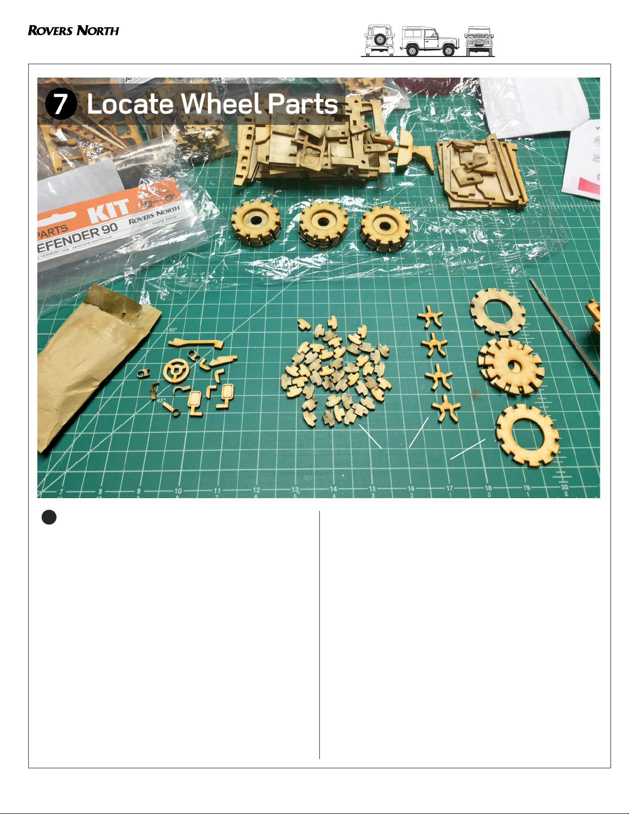
Bu ld Wheels steps 9B-9E
Start w th plac ng two wheel nner p eces together (9B)
and glu ng n each tread p ece unt l all 12 treads are fit as
shown. Make sure the tread p eces are centered, stra ght,
perpend cular to the wheel and n as far as they can go - all
the way down. Let dry.
Place glue around the edges of one s de and offer a
wheel outer p ece (sanded s de down - unsanded s de out)
to the wheel (9C). Th s w ll be the ns de of every wheel that
gets mounted to the axle.
Th s shows how the ns de of each wheel w ll look - th s
s the s de that mounts to the axle.
Th s shows the same as above (9D), but turned on the
s de. You w ll mount the wheel to the axle, then add the wheel
r m lock ng star on the axle hub and glue down the second
wheel outer p ece. See steps 9F-9I for final mount ng and
assembly.
8
B
C
D
E
Oops! Glued your fingers together?
Not to worry - don’t try to separate -
the glued bond w ll always w n!
You can use nail polish remover (acetone) to debond
your glued together fingers. Use the na l pol sh re-
mover n a well vent lated area, add a l ttle b t at a t me
unt l the bonded area starts to soen up. Keep add ng
the remover unt l you can free up your fingers. Th s
m ght take several appl cat ons and attempts, but the
remover w ll succeed n the end.
TIP: Wh le t’s a great exper ment to see how humans
rely on our opposable thumbs, I don’t recommend
gett ng your fingers stuck together w th super glue!
I’ve done t many t mes (by acc dent of course)
and when th s happens, t puts you nto a mass ve
pan c! You can definately feel that f you tr ed to pull
your fingers apart, your sk n w ll be the first to go.
Not a good feel ng at all.
Keep a bottle of nail polish remover close by.

11
ROVERS NORTH, INC. 1319 VT ROUTE 128, WESTFORD, VT 05494 USA www.roversnorth.com (802) 879-0032 RNGWK90
DEFENDER 90 WOOD MODEL PARTS KIT
1
/
1
8th
SEMI
-
SCALE
REALISTIC DISPLAY
Mount Wheels steps 9F-9I
As ment oned n steps 8A-8E, each wheel r m lock ng
hub m ght need to be filed n the center slot to fit and sl p
onto the axles eas er. F le th s and or file the axle slot.
Test fit each wheel on an axle. Make sure to e ther file
the wheel r m lock ng p ece (9F) and / or comb ne w th add -
t onal fil ng of the axle as shown n background photo.
Once you are sat sfied w th how each wheel s ts and
sp ns on the axle, place each wheel on and lock n w th a
wheel r m lock ng hub. Then, add glue to the outs de edge
(9H) and mount the final wheel outs de p ece w th the sanded
s de down, unsanded s de out as shown n (9I).
TIP: Keep glue away from wheel rim loc ing hub and out of
the center red area section shown above.
9
F
G
H
I
Th s shows how each wheel w ll look aer glu ng down
the final wheel outs de p ece.
TIP: Test fit the wheels to make sure they sp n and make them
on the loose s de. Test fit and sp n before final outs de glu ng
and / or more sand ng or file work.

12 ROVERS NORTH, INC. 1319 VT ROUTE 128, WESTFORD, VT 05494 USA www.roversnorth.com (802) 879-0032
RNGWK90
DEFENDER 90 WOOD MODEL PARTS KIT
1
/
1
8th
SEMI
-
SCALE
REALISTIC DISPLAY
Locate Wheel Arch Parts
Wheel arch parts are shown as above. Separate these out
from the k t contents and or entate as shown. The parts are
all dent cal for front and rear. The rear arches have an add -
t onal p ece that gets glued onto the ns de of each chass s
s de, see step 10C.
Prepare parts as before w th fil ng slots and holes as
needed so they fit t ght, but you are st ll able to test fit and
remove.
NOTE: You w ll want to nstall these so the etched s de s
fac ng up as shown n photo above (exhaust s de down).
10
Front Rear
Front Arch Set
Rear Arch Set
Add t onal
p eces for
rear arches

13
ROVERS NORTH, INC. 1319 VT ROUTE 128, WESTFORD, VT 05494 USA www.roversnorth.com (802) 879-0032 RNGWK90
DEFENDER 90 WOOD MODEL PARTS KIT
1
/
1
8th
SEMI
-
SCALE
REALISTIC DISPLAY
Mount Wheel Arches 10A-10E
Test fit each wheel arch p ece pr or to glu ng. Adjust fit
w th file as needed. Apply glue to the flat chass s s de sur-
face as nd cated. Start w th the front lower arch sect on,
then add the rear sect on, see (10B). Make sure to keep
each p ece al gned so the arch surface, front and rear
comes n contact aga nst the chass s, see step (14) for
al gnment.
Mount the top center arch sect on, then apply glue to
the flat chass s s de surface as nd cated for the th nner fill
n arch p eces as shown. Complete both front arches.
Move to the rear and test fit each p ece first, file and
sand as needed before glu ng. Apply glue to the ns de of the
chass s s de and small axle slot. Mount each rear nternal
arch support as shown for both s des.
10
A
B
C
TIP: Take note of how each arch p ece s mounted. Make sure
they are level and square. Keep the bottom surfaces (w th
rounded corners) close to and touch ng the chass s base -
otherw se th s w ll leave a gap when you mount each body
s de.
TIP: You can use a level, the 90˚ tr angle or your eye to ad-
just before the super glue sets.
Complete each rear arch w th the same process as
nd cated n steps 10A-10C.
Each fin shed wheel arch should look l ke the photo
as shown above n (10E).
E
D

14 ROVERS NORTH, INC. 1319 VT ROUTE 128, WESTFORD, VT 05494 USA www.roversnorth.com (802) 879-0032
RNGWK90
DEFENDER 90 WOOD MODEL PARTS KIT
1
/
1
8th
SEMI
-
SCALE
REALISTIC DISPLAY
Locate Rear Body Parts
The rear body parts are shown as above. Separate these out
from the k t contents and or entate w th etched side facing out
as shown.
- Rear body fac ng x1
- Rear door (only used f NOT mount ng rear spare wheel k t) x1
(See (11A) below to mount Rear Spare Wheel K t)
- Rear door h nges x2
- Rear bumper x1
- Rear h tches x3
ATTENTION! : If you purchased a Rear Spare Wheel it
(RNGWKDRS) NOW is the time to locate and install these parts
on step 11C. You w ll replace the Defender 90 (or 110) base k t
rear door (11A) w th the new rear door (w th slot for rear t re
mount) from the rear spare wheel k t package.
11
RNGWKDRS
If you would l ke to
add a rear spare
wheel k t, order one
before cont nu ng the
bu ld process. Please
v s t roversnorth.com
and or g ve us a call
to order RNGWKDRS.
A

15
ROVERS NORTH, INC. 1319 VT ROUTE 128, WESTFORD, VT 05494 USA www.roversnorth.com (802) 879-0032 RNGWK90
DEFENDER 90 WOOD MODEL PARTS KIT
1
/
1
8th
SEMI
-
SCALE
REALISTIC DISPLAY
Assemble Rear Body and Door
Offer the rear body part to the chass s, test fitment first before
glu ng. Use the 90˚ tr angle to make sure t s perpend cular to the
chass s. Glue as nd cated, keep aga nst 90˚ tr angle wh le the glue
s dry ng.
Install rear bumper and then rear h tches as shown. Apply
a drop of glue to ns de of slots first before add ng each part.
Install rear door as shown. Glue top rear door h nge n first,
then p vot and nstall lower door h nge n as shown. Apply only a
drop or so of glue - make sure that glue doesn’t get nto door p vot
area.
Install a small p ece of wood to make a door stop - mount
aga nst rear door and chass s as shown. Th s keeps the rear door
from clos ng nto the back compartment area. Th s part should be
ncluded n the k t, f you loose t, a wooden match st ck p ece w ll
work also.
11
B
CD
E
Install
Rear Door
Stop Here
E

16 ROVERS NORTH, INC. 1319 VT ROUTE 128, WESTFORD, VT 05494 USA www.roversnorth.com (802) 879-0032
RNGWK90
DEFENDER 90 WOOD MODEL PARTS KIT
1
/
1
8th
SEMI
-
SCALE
REALISTIC DISPLAY
Mount Bulkhead, Seatbase Parts
Mount the bulkhead as shown, use a few drops of glue to fix.
At th s t me you can choose to make your Defender RHD or LHD,
I made th s Defender 90 bu ld LHD as shown.
Use the 90˚ tr angle to check bulkhead for proper al gnment
and accuracy.
Mount the seatbase as shown above. Place a few drops of
glue onto the slots shown n (12A) before secur ng part.
Mount the steer ng column and steer ng wheel as shown
above. Place a drop or so of glue nto the slots or holes before
fix ng each part.
- Bulkhead x1
- Seatbase x1
- Steer ng column x1
- Steer ng wheel x1
12
A
B
C

17
ROVERS NORTH, INC. 1319 VT ROUTE 128, WESTFORD, VT 05494 USA www.roversnorth.com (802) 879-0032 RNGWK90
DEFENDER 90 WOOD MODEL PARTS KIT
1
/
1
8th
SEMI
-
SCALE
REALISTIC DISPLAY
Mount Seatback, Roll Bar Parts
Mount the seatback as shown, use a few drops of glue to fix.
Use the 90˚ tr angle to check bulkhead for proper al gnment
and accuracy, hold n place wh le glue dr es. Th s step s mpor-
tant, because the body s des need to fit onto the small s de posts
on the roll bar. L ned up stra ght, they should fit well.
Double check and make sure the seatback and roll bar are
all the way down and bottom s flush w th the chass s, see (13B)
before the glue dr es.
- Seatback, Roll Bar x1
13
A
B

18 ROVERS NORTH, INC. 1319 VT ROUTE 128, WESTFORD, VT 05494 USA www.roversnorth.com (802) 879-0032
RNGWK90
DEFENDER 90 WOOD MODEL PARTS KIT
1
/
1
8th
SEMI
-
SCALE
REALISTIC DISPLAY
Mount Body S de Parts
Test fit each body s de p ece for fitment before glu ng, make
adjustments as needed w th the file. Make sure that you have the
etched side facing out on each body s de before glu ng.
Mount the each body s de as shown above, use a few drops
of glue to fix as nd cated. If you add the glue aer fitment, th s
can be appl ed on the ns de as shown. Also apply near and
around bulkhead.
Al gn rear body upr ght sect on to be flush aga nst each body
s de. Al gn roll bar to fit w th n etched l nes on the outs de.
- Body S de Le x1
- Body S de R ght x1
14

19
ROVERS NORTH, INC. 1319 VT ROUTE 128, WESTFORD, VT 05494 USA www.roversnorth.com (802) 879-0032 RNGWK90
DEFENDER 90 WOOD MODEL PARTS KIT
1
/
1
8th
SEMI
-
SCALE
REALISTIC DISPLAY
Mount Seatback, Roll Bar Parts
Test fit the w ndscreen before mount ng and adjust slots w th
file f necessary. Mount the w ndscreen as shown above; place a
few drops of glue onto door frame before mount ng w ndscreen.
Secure w th glue on the base of w ndscreen to bulkhead.
Test fit front gr lle part before glu ng; adjust slots w th file as
needed. Place glue to s des of gr lle and lower chass s and mount
to veh cle. Keep al gnment stra ght, mak ng sure gr lle s flush w th
ends of each body s de.
Add add t onal glue to ns de of lower gr lle area pr or to
mount ng bonnet n step (16).
- W ndscreen x1
- Front Gr lle x1
15
A
B

20 ROVERS NORTH, INC. 1319 VT ROUTE 128, WESTFORD, VT 05494 USA www.roversnorth.com (802) 879-0032
RNGWK90
DEFENDER 90 WOOD MODEL PARTS KIT
1
/
1
8th
SEMI
-
SCALE
REALISTIC DISPLAY
Mount ng Bonnet Parts
Test fit the bonnet base p ece for fitment before glu ng,
make adjustments as needed w th the file. Make sure that
you have the etched side facing out w th s de w ng top vents
show ng.
Mount the bonnet base as shown above, use a few drops
of glue to fix on top of ent re r m top of gr lle and w ngs, let
dry before proceed ng to next step.
Test fit bonnet top nto slot on bulkhead. A few m ll me-
ters back from the front edge (3-4mm) s the locat on of
where you w ll apply a few drops of glue to fix the front of the
bonnet down; see glue locat ons on (16A1).
TIP: I prefer to place a few drops of glue d rectly on the
unders de of the bonnet front edge so t w ll be h dden when
mounted.
16
A1
B
Test fit each bonnet s de as shown above. Place a few
drops of glue nto the slots as nd cated. Use a small drop of
glue towards the front where the part s very narrow (locate
the glue n the small valley and where t has some contact
area).
- Bonnet Base (16A1) x1
- Bonnet Top x1
- Bonnet S des x2
C
Table of contents