RS PRO RSPD3303C User manual

Quick Start
RSPD3303C
Programmable DC Power Supply

2
General
Safety
Summary
Please
review
the
following
safety
precautions
carefully
to
avoid
personal injury or damage to this product or any product connected
to
it.
To
prevent
potential
danger,
please
use
the
instrument
as
specified.
Use
proper
power
cord
Only the power cord designed for the instrument and authorized by
local country could be used.
Power
supply
AC Input Voltages: 100V/110V/220V/230V ±10%, 50/60Hz.
Use
proper
fuse
The fuse types: 100V/110V(T6.3A/250V) 220V/230V
(T3.15A/250V)
Make
sure
to
use
the
correct
type
of
fuse
before
turning
on
the
instrument.
Do not connect the power cord before replacing the fuse.
Find
out
the
reason
why the
fuse
burned
out
before
replacing the
fuse.
Ground
the
instrument
The instrument is
grounded through the protective terra conductor
of the power cord. To avoid electric shock, the grounding conductor
must
be
connected
to
the
earth.
Make
sure
that
the
instrument
is
properly grounded before any inputs or outputs.
Observe
all
terminal
ratings
To
avoid
fire
or
electric
shock,
please
observe
all
ratings
and
symbols on the instrument. Read this guide carefully to know more
details about the ratings before connection.

3
Keep
proper
ventilation
Inadequate
ventilation
may
cause
an
increase
of
temperature,
which
will
lead
to
further
damage.
Please
keep
proper
ventilation
and
check
the
fan
and
air-vents
regularly
when
using
the
instrument.
Operate
condition
Location: indoor, no strong light, almost no Interfering pollution
Comparative humidity: <80%
Altitude: <2000m
Temperature: 0℃to 40℃
Do
not
operate
in
an
explosive
atmosphere
To
avoid
personal
injury
or
damage
to
instrument,
please
do
not
operate in an explosive atmosphere.
Keep
surface
of
the
product
clean
and
dry
To avoid dust or moisture in the air, which may influence the
performance of the instrument, please keep surface of
the product clean and dry.

4
Safety
Terms
and
Symbols
Terms
may
appear
on
the
product:
DANGER
: Indicates direct injury or hazard that may happen.
WARNING
: Indicates potential injury or hazard that may happen.
CAUTION
:
Indicates
potential
damage
to
the
instrument
or
other
property that may happen.
Symbols
may
appear
on
the
product:
Hazardous
Protective
Warning
Earth
Power
Voltage
Earth
Ground
Ground
Switch

5
Brief
Introduction
RSPD3303C
LED
series
Programmable
DC
Power
Supply
is
convenient,
flexible
and
multi-function.
It
is
designed
with
three
groups
of
independent
output
terminals,
the
output
voltage
of
two
groups is adjustable and another group is fixed to select: 2.5V, 3.3V,
and
5V.
The
instrument
also
provides
output
short
circuit
and
overload protection.
Main
Features
Three independent output channels, two of which are
controllable, with a total power up to 195W
Compatible design for power voltage: 100V, 110V, 220V and
230V to satisfy different power network
Capable of saving and recalling set parameters
Perfect PC software to realize the real-time control through
USBTMC.

6
Chapter
1
Quick
Guide
In
this
chapter,
we
mainly
introduce
the
panel
display
interface
and inspecting the new machine.Reading
the
following
steps
will
give
you
a
quick
understanding on operation.
General
Inspection
1. Inspect the shipping container.
Keep
the
damaged
shipping
container
or
cushioning
material
until
the
contents
of
the
shipment
have
been
completely
checked
and
the
instrument
has
passed
both
electrical
and
mechanical tests.
2.
Inspect the instrument.
If
there
are
instruments
found
damaged,
defective
or
failure
in
electrical and mechanical tests, please contact us.
3.
Check the accessories.
Please check the accessories according to the packing list. If the
accessories
are
incomplete
or
damaged,
please
contact
us
.

7
Safety
Considerations
To
ensure
that
the
instrument
can
work
normally,
please
conduct
necessary inspection before using the RSPD3303C.
Input
Power
Requirement
The RSPD3303C
allows
a
50Hz/60Hz frequency,
and
four levels
of
AC
power:
100V/120V/220V/230V.
You
can
select
required
power
voltage
with
the
“DIP
Switch
”
at
the
rear
panel
according
to
the
actual demand.
Warning
To switch to the required power voltage, please disconnect the
power cord first.
Electrical
Check
Please use the power cord provided and connect the
instrument to AC power. Check the power as follows.
1.
Connect the power supply
Warning
To avoid electric shock, please make sure that the instrument is
grounded correctly.
2.
Turn on the power switch
Press
the
button
POWER
to
enter
boot
interface,
the
system
then returns to the default setting.

8
The
Front
Panel
1
2
3
4
5
6
7
8
9
10 11 12 13 14 15
NO.
Description
NO.
Description
1 Logo 9 CH3 DIP Switch
2 LED Display 10 Power Switch
3 Model 11 CH1 Output Terminal
4 Configuration button 12 Ground Terminal
5 Multi-function knob 13 CH2 Output Terminal
6 FineAdjust button 14 CV/CC Indicator Light
7 Voltage/Current button 15 CH3 Output Terminal
8 Channel Control button

9
Instruction
for
Buttons
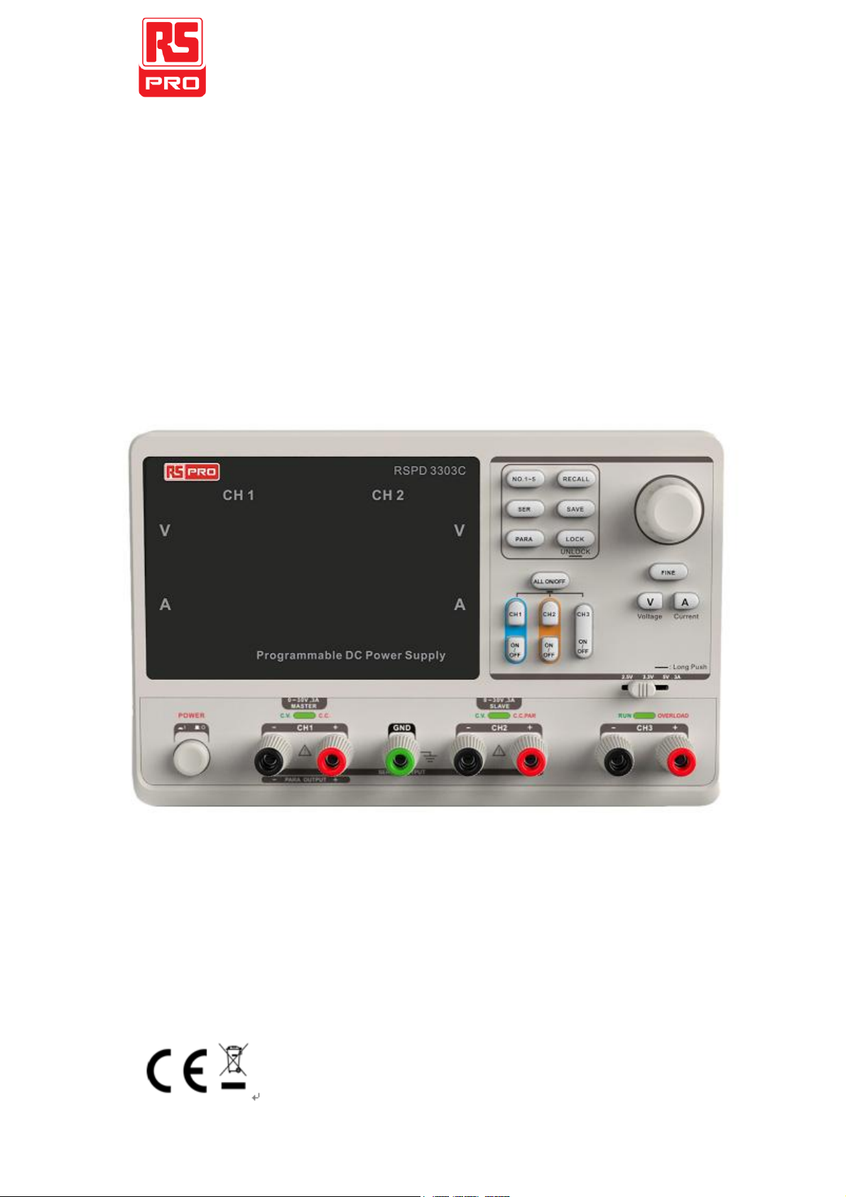
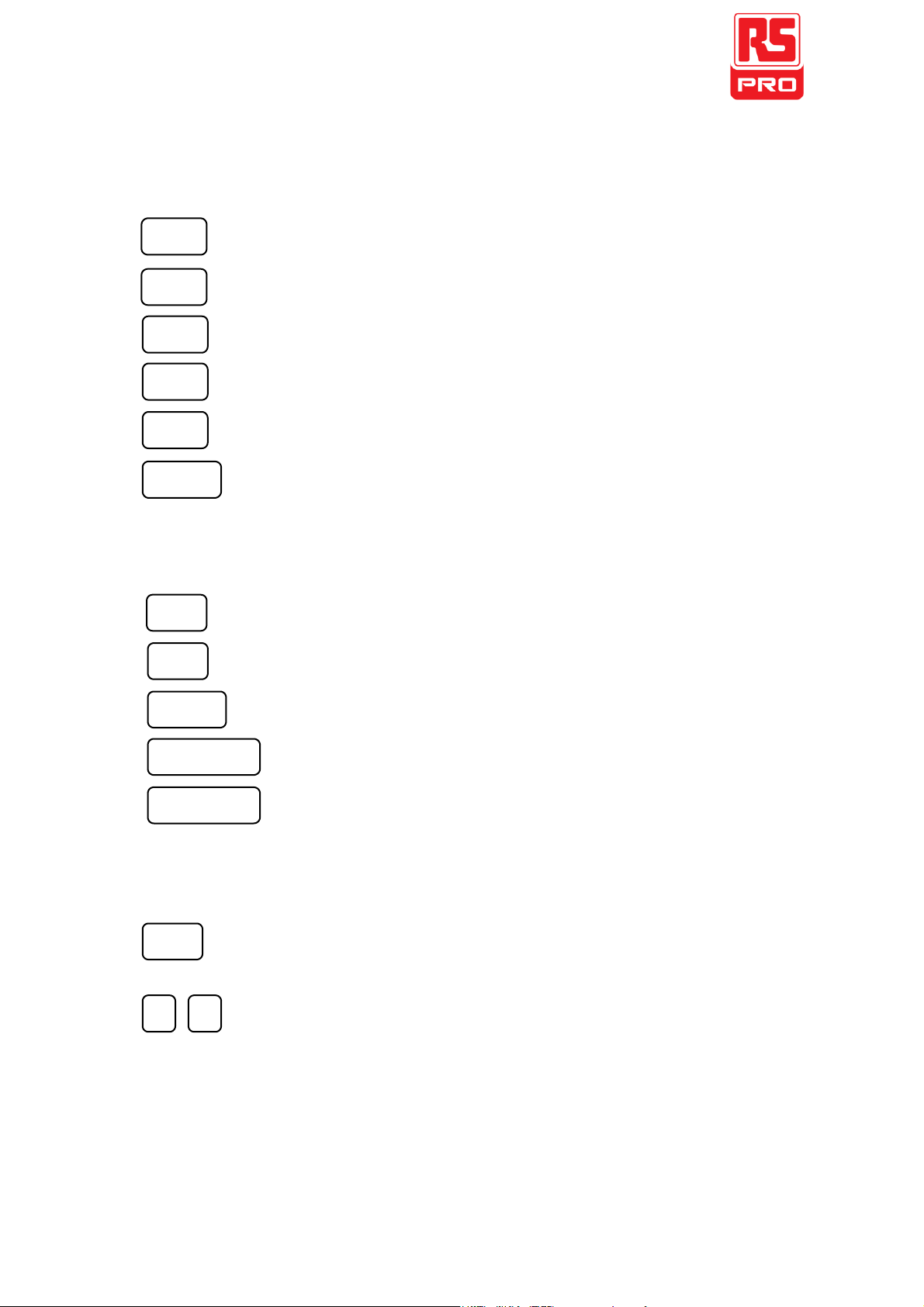
Buttons for setting parameters
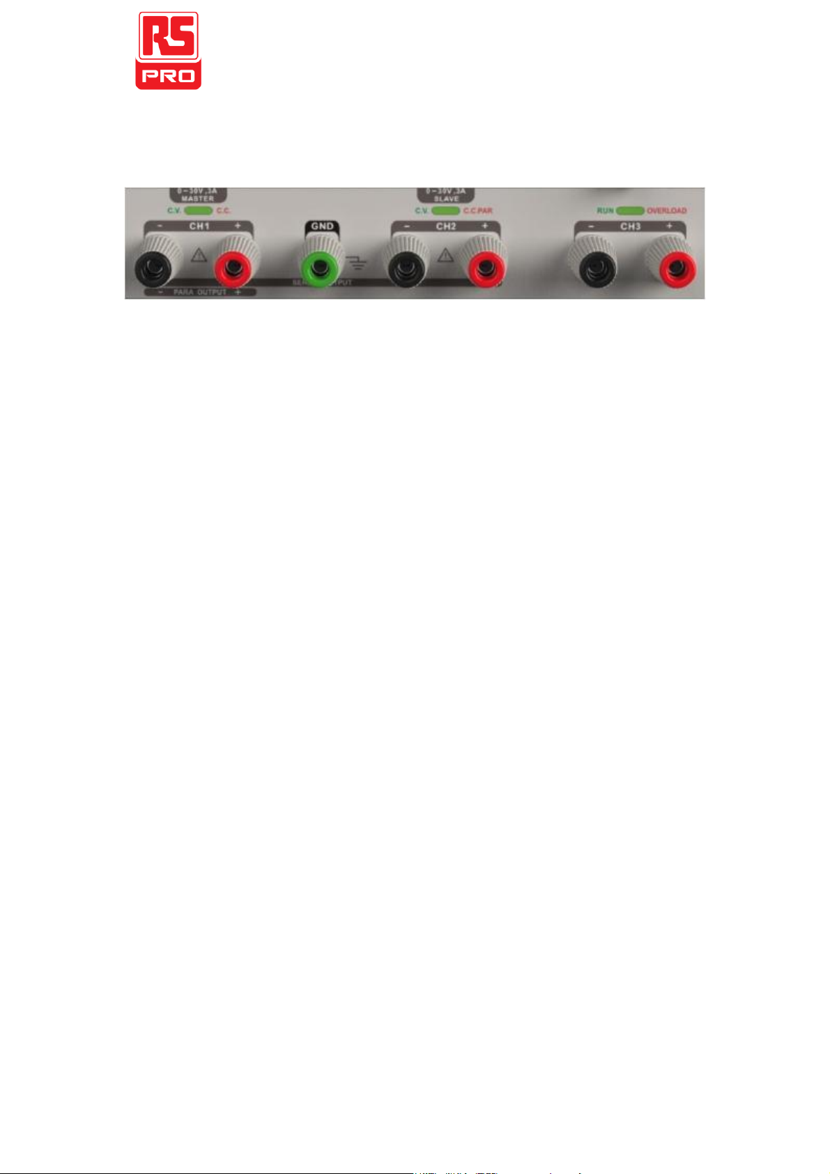
NO.1-
5
: Press the button to
choose the storage location
SER
PARA
LOCK
SAVE
: Press the button to set series mode of CH1/CH2.
: Press the button to set parallel mode of CH1/CH2.
: Long press the button to turn on/off the keylock function.
:Press the button to enter the storage system for saving files.
RECALL
: Press the button to enter the storage system for recalling files.
Buttons
for
controlling
the
channel
CH1
CH2
: Press the button to select CH1 as the current channel
: Press the button to select CH2 as the current channel
ON/OFF
: Press the button to turn on/off output of the current channel
CH3
ON/OFF
: Press the button to turn on/off the CH3 output.
ALL
ON/OFF
Other
buttons
: Press the button to turn on/off all channels
FINE
V
A
: Press the button to open the fine adjust function and modify the
parameter in the minimum step
: To select between voltage and current.

10
The
Front
Panel
Terminals
The positive/negative output terminals of CH1, CH2, CH3, and the
common GND for CH1,
CH2 are located on the front panel. Refer
to later “control panel operation” for wiring method details.

11
User
Interface
1
2
3
1: Channel Logo
2 : Voltage set/Readback value
3 : Current set/Readback value

12
The
Rear
Panel
1
2
7
6
5
4
3
Description:
1
Warning message
2
AC power DIP switch
3
Instruction for theAC input voltage
4
AC power socket
5
Fan vent
6
CE certification mark
7
USB interface

13
Output
Checking
To
ensure
the
instrument
is operating
correctly,
please check the output voltage and current before load is connected.
1.
Output
voltage
checking
(1)
With
the
instrument
no
load,
turn
on
the
power,
and
make
sure the current value displaying is not zero
(2) Check the output voltage of CH1/CH2
Turn on CH1/CH2 channel and the instrument will work
in
CV
mode.
Check
whether
the
voltage
value
is
adjustable from 0V to 32V.
2.
Current
output
check
(1) Turn on the power.
(2) Check the output current of CH1/CH2.
Use an insulated wire to connect the positive and negative
terminal of CH1/CH2
(3) Turn on CH1/CH2
Select voltage and revolve the knob to set the value to 32V
Select current and revolve the knob to set the value to 0A
Check
whether
the
current
value
is
adjustable
from
0A
to
3.2A.

14
Chapter
2
Control
Panel
Operation
In
this
chapter,the
function
and
operation
of
RSPD3303C
control
panel
will
be
introduced
in
detail
to
give
you
an
all-around
understanding of it.
Brief
introduction
Output Summary
CH1/CH2 Independent Output
CH3 Independent Output
Parallel Output
Series Output
Save and Recall

15
Output
Summary
RSPD3303C
is
designed
with
three
independent
outputs,
two
of
which are adjustable in voltage value and the other includes a set of
selectable voltage values: 2.5V, 3.3V or 5.0V.
Independent/Parallel/Series
RSPD3303C
has
three
output
modes:
independent,
parallel
and
series that
could be selected through the track
switch on the front
panel.
In
independent
mode,
the
output
current
and
voltage
are
controlled respectively.
In parallel
mode, the current value is twice
that of single channel. In the series mode, the voltage value is twice
that of single channel.
Constant
Current/Voltage
In constant current mode (series/track mode), the current value is rated.
When the voltage value are under its rating, the indicator light displays
red. The instrument will automatically return to constant voltage mode
when the current value is under rated. In parallel 1 mode, the accessory
channel remains in constant current mode neglecting shift of the current
value.
In constant voltage mode, the voltage value is rated. When the current
value are under its rating, the indicator light dispays green.
The instrument will turn to constant current mode when the current
value returns to its rating.

16
CH1/CH2
Independent
Output
Instruction
CH1
and
CH2
are
working
in
independent
mode
and
insulated from the ground.
Output ratings 0~30V/0~3A(Max: 32V, 3.2A)
Operation
steps
1. Make sure that parallel/series mode is off.
2. Connect load to the positive and negative terminals of CH1/CH2.
3. Set the voltage (current) value of CH1/CH2: Firstly, press V (or A)
to select the voltage (current) parameter needed to modify. Then
revolve
the
multi-function
knob
to
set
the
wanted
value
(You
could press FINE to make accurate adjusting).
Coarse adjusting: 0.1V or 0.1A each step.
Fine adjusting: the least precision each step.
4. Open output: Press ON/OFF button to turn on the output, the
channel
works
in
CC
or
CV
mode
and
its
indicator
light
gets
lit immediately.

17
CH3
Independent
mode
Instruction
CH3
works
independently
from
CH1,
CH2,
and
its
voltage and current ratings are: 2.5V, 3.3V, 5V, 3A.
Output ratings 2.5V/3.3V/5V, 3A
Operation
steps:
1.
Connect
the
load
to
the
positive
and
negative
terminal
of
CH3
channel.
2.
Select
the
required
voltage
value
by
moving
the
“DIP
switch”
of
CH3.
3. Open the output: Press ON/OFF button to turn on the channel
and the indicator light gets lit immediately.
CV
CC
When the current value gets higher than 3A, the overload indicator
light turns red and the working mode of CH3 turns to CC mode from
CV mode.
Note:
“Overload” does not mean abnormal operation.

18
CH1/CH2
Series
Mode
Instruction
:
In the series mode, CH1 and CH2 are linked internally
into
one
channel
controlled
by
CH1.
The
output
voltage
value
is
twice
compared
with
that
of
single
channel.
Output ratings 0~60V/0~3A(Max: 64V, 3.2A)
Operation
steps
:
1. Press the SER to start the Series mode, and the indicator light
turns bright
2.
Connect the load to the positive terminal of CH2 and the
negative terminal of CH1
3.
Turn on CH1 and set its current value to 3A. In the default setup,
the instrument works in “Coarse”, you can turn to “Fine” by
pressing FINE
Coarse: 0.1V or 0.1Aeach step
Fine: the least precision each step
4.
Turn on CH1and set the output voltage/current value by
revolving themulti-function knob
5.
Press ON/OFF button to open the output.
Note:
You can identify the current working state “CC” or “CV” by
referring to the indicator light.(red means CV, green means CC).

19
CH1/CH2
Parallel
Mode
Instruction
In the parallel mode, CH1 and CH2 are linked internally
into one channel controlled by CH1. The output current
value is twice as much as the single channel.
Output ratings 0~30V/0~6A(Max: 32V, 6.4A)
Operation
steps:
1.
Press the PARA button to start Parallel mode, and the indicator
light turns bright immediately
2.
Connect the load to the positive and negative terminals of CH1
3.
Press ON/OFF button to open the output and the indicator light
turns bright.
Turn on CH1 and set its output voltage/current value by
revolving the multi-function knob. In the default setup, the
instrument works in “Coarse”, you could turn to “Fine” by
pressing FINE button.
Note:
You can identity the current working state “CC” or “CV” refer
to the indicator light.(red means CV, green means CC). In
parallel mode, CH2 only works in CC mode.

20
Save
and
Recall
Five groups of setups can be saved in memory. Contents of setups
including:
Independent/series/parallel mode
Output voltage/current value
Steps
for
saving
setup
1. Set the state needed to save
2. Press SAVE to enter the save interface
3. Select the wanted file group by pressing NO.1-5
4. Press
SAVE
again to save the current state to the specified file
group.
Steps
for
recalling
setup
1.
Press RECALL to enter the recall interface
2.
Select the wanted file group by pressing NO.1-5
3.
Press RECALL again to read the previously saved file.
Table of contents
Other RS PRO Power Supply manuals