RS 303-2101 User manual

Issued / Pubblicato 03/2001 V10799
114
13
A
C
G
A
B
DEFH
AB
CD
12345
AB
Figures / Figura
Internal PC Hub
Instruction Leaflet
Foglio d’instruzioni
PC Hub Interno
1
3
4
Internal Hub
A. Station port
B. Daisychain port
Hub Interno
A. Porta stazione
B. Porta Daisychain
A. Red Line pin 1 A. Piedino uno linea rossa
2
LED Display/Module
A. Power
B. Link/Rx
C. Collision
D. Partition
Visualizzazione/
modulo LED
A. Accensione
B. Collegamento/Rx
C. Interferenza
D. Partizone
A. Red Line +5V
B. Red Line Pin 1
C. To workstation 1
D. To workstation 2
E. To workstation 3
F. To workstation 4
G. To another hob Hub
or server 5
H. Insert to rear expansion
slot
A. Linea rossa da +5V
B. Piedino uno linea rossa
C. A stazione di lavoro 1
D. A stazione di lavoro 2
E. A stazione di lavoro 3
F. A stazione di lavoro 4
G. A un altro hub o server 5
H. Inserire nello slot di
espansione posteriore

2
V10799
10Base-T Ethernet Hub 303-2101
Introduction
A unique 10 Base -T Ethernet Hub designed to fit into a PC Base unit
by utilising a spare expansion slot enabling access to the 5 RJ-45 ports
to the rear of the PC. The unit is supplied with a Diagnostic LED panel
which fits in a spare 3.5” drive bay to the front of the PC. The design
provides an extremely practical and fully functional solution for small
office/ home office, workgroups, conference and seminar rooms.
Features
●Modular 5 port 10 Base-T Hub
●Complies with IEEE802.3 Ethernet specifications
●Fits easily into a PC Base unit using a spare expansion slot
●Diagnostic LED Panel fits in a spare 3.5” drive bay
●5 fully shielded RJ-45 ports
●An uplink port (port 5) for easy expansion
●Auto partitioning
●Powered by the PC
●Ideal for SOHO environment, departmental workgroups, conference
and seminar rooms
Hardware description
See figures 1 and 2.
Hardware installation
Before installation:
1. Power off and disconnect the power cable from your computer.
2. Remove static electricity from your hands by touching the metal
back of the computer case.
(A) Internal Hub
1. Remove the cover from your computer.
2. Select an empty expansion slot and remove its slot cover, keep the
screw for later use.
3. Place the Internal Hub in the exposed slot. Fasten the Internal Hub
securely with the slot cover screw.
4. Select a spare computer power cable connector (for a 3.5” FDD)
and insert it into the internal Hub power supply socket.
(B) LED Display Module
1. Select a spare 3.5” bay and remove its front cover plate.
2. Place the Display in the 3.5” bay. Align the Display screw holes with
the screw holes from the 3.5” bay. Fasten the Display with a screw
on each side of the 3.5” bay.
3. Connect the Display and Internal Hub with the 14-pin flat cable,
ensure the red wire of the flat cable is connected to both pin 1
sockets on the Display and Internal Hub.
(C) Connect to workstations
1. Connect your workstation to any available RJ-45 port on the hub
using UTP or STP cable.
2. All end-node devices must be within 100 meters of the connected
hub. Using the hub in a stand-alone configuration, you can network
up to 4 workstations.
J-45 ports connection
LED Indicators
RS Components shall not be liable for any liability or loss of any nature (howsoever
caused and whether or not due to RS Components’ negligence) which may result
from the use of any information provided in RS technical literature.
LED Colour Indication
Power Green Power indicator
Collision indicator
Collision Yellow Flashes to show network collision
Unlit No activity
Link-RX Green RJ-45 port linked
Flashes to indicate traffic
is being received
Partition Red RJ-45 port partitioned
RJ-45 Ports UTP/STP cable End-node device
Connection to a
Straight-through workstation or server
cabling
Station port Connect to another
1-4 hub’s daisy-chain port
Crossover cabling Connect to another
hub’s station port
Straight through Connect to another
cabling hub’s station port
Daisy-chain Connection to a
workstation or server
Crossover cabling Connect to another
hub’s daisy-chain port
S Stock No.

3
Hub Ethernet 10BASE-T 303-2101
Introduzione
Hub adatto per unità PC Base. Può essere montato utilizzando uno slot
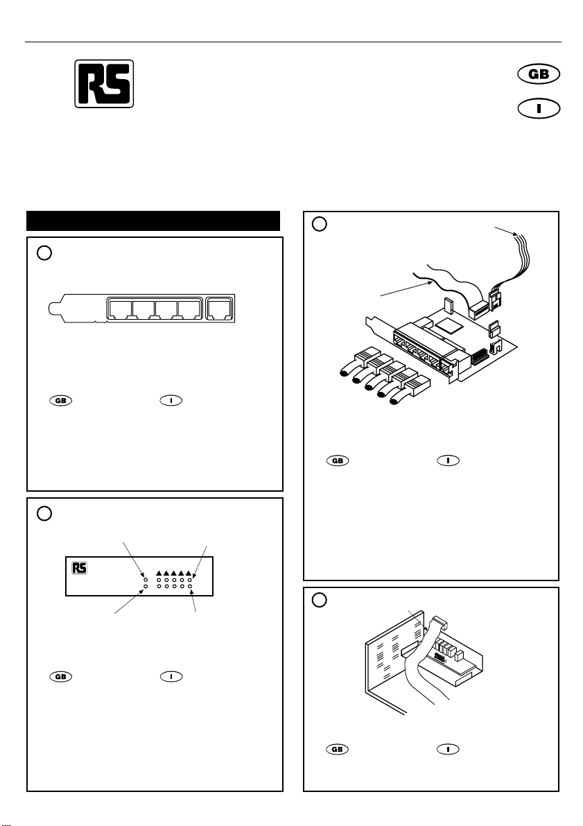
di espansione di riserva che consente l'accesso alle 5 porte RJ-45 sul
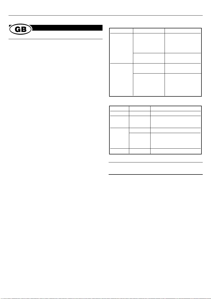
retro del PC. L'unità è dotata di un pannello LED diagnostico da
installare nel vano dell'unità 3.5" di riserva sulla parte anteriore del PC.
L'unità rappresenta una soluzione estremamente pratica e funzionale
per abitazioni, piccoli uffici, gruppi di lavoro e sale per conferenze o
seminari.
Caratteristiche
●Hub 10 Base-T con 5 porte modulari
●Conforme alle specifiche Ethernet IEEE802.3
●Può essere montato con facilità su qualsiasi unità PC Base
utilizzando lo slot di espansione di riserva
●Il pannello LED diagnostico può essere installato nell'alloggiamento
dell'unità 3,5" di riserva
●5 porte RJ-45 completamente schermate
●Porta uplink (porta 5) per espansione
●Partizione automatica
●Alimentato dal PC
●Ideale per ambienti SOHO, gruppi di lavoro di settore, sale per
conferenze e seminari
Descrizione dei componenti hardware
Figura 1 e Figura 2
Installazione dei componenti hardware
Prima dell'installazione
1. Spegnere e scollegare il cavo di alimentazione dal computer.
2. Scaricare l'elettricità statica dalle mani toccando il retro
dell'intelaiatura del computer.
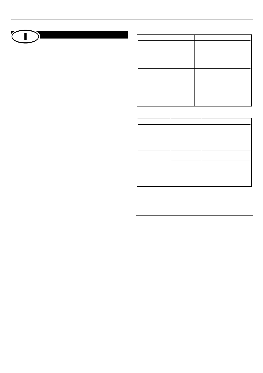
(A) Hub interno
1. Rimuovere il coperchio del computer.
2. Scegliere uno slot di espansione vuoto e rimuovere il relativo
coperchio. Riporre le viti in modo da poterle utilizzare in seguito.
3. Inserire l'hub interno nello slot di espansione. Fissare saldamente
l'hub interno con la vite del coperchio dello slot.
4. Scegliere un connettore di alimentazione di riserva del computer
(per FDD da 3,5") e inserirlo nella presa di alimentazione dell'hub
interno.
(B) Modulo LED
1. Selezionare un alloggiamento da 3,5" di riserva e rimuovere il
relativo coperchio anteriore.
2. Inserire il modulo nell'alloggiamento. Allineare i fori delle viti del
modulo con quelli dell'alloggiamento. Fissare il modulo con una vite
su ciascun lato dell'alloggiamento da 3,5".
3. Collegare il modulo e l'hub interno utilizzando un cavo piatto a 14
piedini. Assicurarsi che il cavo rosso sia collegato alla presa del
modulo e dell'hub interno.
(C) Collegamento alle stazioni di lavoro
1. Collegare la stazione di lavoro a qualsivoglia porta RJ-45
disponibile sull'hub utilizzando un cavo UTP o STP.
2. Tutte le periferiche a nodo terminale devono trovarsi entro 100 metri
dell'hub collegato. Utilizzando l'hub in una configurazione
autonoma, è possibile collegare in rete fino a 4 stazioni di lavoro.
Connessione porte J-45
Indicatori LED
La RS Components non si assume alcuna responsabilità in merito a perdite di
qualsiasi natura (di qualunque causa e indipendentemente dal fatto che siano dovute
alla negligenza della RS Components), che possono risultare dall’uso delle
informazioni fornite nella documentazione tecnica.
LED Colore Indicazione
Alimentazione Verde Indicatore di potenza
Indicatore di interferenza
Interferenza Giallo Lampeggia per indicare
un’interferenza di rete
Non illumninto Nessuna attività
Collegamento Verde Porta RJ-45 collegata
RX Lampeggia per indicare
traffico in entrata
Partizione Rosso Porta RJ-45 partizionata
Porte RJ-45 Cavo UTP/STP Dispositivo con nodo terminale
Collegare a una stazione
Cablaggio diretto di lavoro o server
Port stazione Collegare a un altra porta
1-4 Daisychain dell’hub
Cablaggio a incrocio Collegare a un altra porta
isolato della stazione hub
Cablaggio diretto Collegare a un altra porta
della stazione hub
Collegare a una stazione
Daisy-chain Cablaggio a incrocio di lavoro o server
isolato Collegare a un altra porta
Daisychain dell’hub
S Codici.
V10799

V10799
Table of contents
Languages:
Other RS Switch manuals