RSI VIDEO TECHNOLOGIES XT610 Owner's manual

Document #2000-XTIN
4455 White Bear Parkway
White Bear Lake, MN 55110
877-206-5800
COMPLETE SETUP AND PROGRAMMING MANUAL
FOR
XT610/XTX610/XTO610 GPRS PANELS
*A Videofied CMA601 / XMB611(June 2011) Alphanumeric Keypad or Frontel TMT2 is
required for programming and maintenance*
CMA601
XMB611

2011/11/10 Ed 1.5 Setup and Programming manual for XT series GPRS
2 | P a g e
4455 White Bear Parkway, Suite 700
White Bear Lake, MN 55110
Table of Contents
Page
FCC Guidelines 3
Basic Guidelines 4
Introduction 5
Initial Programming 6-14
Entering Badges and Access Codes 15
Choosing Siren Options 16
Testing to Central Station 17
Disabling Monitoring 18
Testing GPRS Level 19
Testing Device RF Level 20
Connecting a GPRS Antenna 21
Arming Input Wiring Diagram 21
Programmable Input Configuration 22-24
Programmable Output Configuration 25-27
Configuring Scheduling 28-30
Enabling External RF Antenna 31
Mounting XT/XTX 32
Mounting XTO 32-33
Troubleshooting 34-36
Central Station not getting Video 34
Central Station not getting any signals 35
Panel saying Connected with Monitor Station 35
Unable to record device or getting ‘Pairing Failure’ error 36
After Initial Programming Flow Chart 36-41
Addendum 42

2011/11/10 Ed 1.5 Setup and Programming manual for XT series GPRS
3 | P a g e
4455 White Bear Parkway, Suite 700
White Bear Lake, MN 55110
Regulatory Information for USA and Canada
FCC Part 15.21 Changes or modifications made to this equipment not expressly approved by RSI
Video Technologies may void the FCC authorization to operate this equipment.
FCC Part 15.105 Class B
This equipment has been tested and found to comply with the limits for a Class B digital device,
pursuant to Part 15 of the FCC Rules. These limits are designed to provide reasonable protection
against harmful interference in a residential installation. This equipment generates uses and can
radiate radio frequency energy and, if not installed and used in accordance with the instructions,
may cause harmful interference to radio communications. However, there is no guarantee that
interference will not occur in a particular installation. If this equipment does cause harmful
interference to radio or television reception, which can be determined by turning the equipment off
and on, the user is encouraged to try to correct the interference by one or more of the following
measures:
Reorient or relocate the receiving antenna.
Increase the separation between the equipment and receiver.
Connect the equipment into an outlet on a circuit different from that to which the receiver is
connected.
Consult the dealer or an experienced radio/TV technician for help.
Radiofrequency radiation exposure information according 2.1091 / 2.1093 / OET bulletin 65
This equipment complies with FCC radiation exposure limits set forth for an uncontrolled
environment. This equipment should be installed and operated with minimum distance of 20 cm
between the radiator and your body.
This transmitter must not be co-located or operating in conjunction with any other antenna or
transmitter.
This device complies with Part 15 of the FCC Rules and with RSS-210 of Industry Canada.
Operation is subject to the following two conditions:
(1) this device may not cause harmful interference, and
(2) this device must accept any interference received, including interference that may cause
undesired operation.

2011/11/10 Ed 1.5 Setup and Programming manual for XT series GPRS
4 | P a g e
4455 White Bear Parkway, Suite 700
White Bear Lake, MN 55110
Basic Setup Guidelines for Installation and Programming
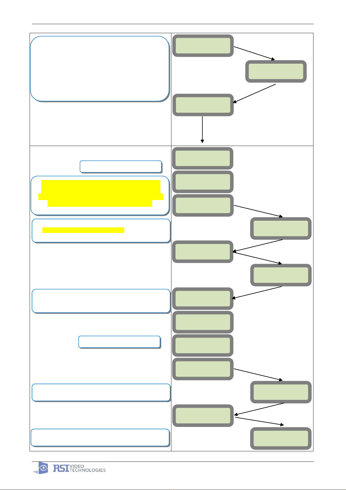
SETUP AND PROGRAM
1) Obtain the account number, IP address, and port number from the Central Station.
2) Activate the SIM card and obtain the APN code, username, and password by calling your
cellular provider. *Note: Do step 1 and 2 the day before the install.
3) Setup and program the system in the office or in your vehicle. DO NOT MOUNT THE
DEVICES. (Page 4-12)
4) Add user codes and or badges after initial programming. (Page 13)
5) Silence the siren before you set the alarm for testing. (Page 15)
6) Arm the system and send one alarm signal and video to the central station. Call the central
station and make sure they received the signal. (Page 16)
*Note : Before deploying the system you will want to disable monitoring so that signals are
not sent until you are ready to send them. (Page 14)
DEPLOYING THE SYSTEM ON SITE
7) Put the panel where you want to mount it and run the GPRS test to make sure you are
receiving good cell signal. If you get 3/5 or better, mount the panel. If not, you will need to
move the panel and run the test again.* (page 17)
8) Now you are ready to deploy the devices. Use your keypad to run the RF test for each
device. If you get a 9/9 for your RF test on the first device, then mount it. If not, you will
need to move the device to get optimal signal.* (Page 18)
*Note: If you are not getting an appropriate GPRS or RF level, you
can add an external antenna for either signal. (Not available for the
XL600)
*Note: Re-enable monitoring before you send signals (Page 14)
8.5) If you are currently using TMT Installer to program the system you can take
still pictures from each MotionViewer using the software. See TMT Installer
Users Manual available on support.videofied.com.
9) Once you have everything mounted, you are ready to arm the system and set off each
device. Make sure you stand in front of each MotionViewer for 10 seconds so the central
station has some video to look at. (Page 16)
10) After you have sent signals to central station, call to verify.
The following pages will go through each one of these steps and, if you have any issues, you cannot
resolve, please feel free to call technical support at 1-651-855-7800 EXT 45, 1-877-206-5800 EXT 45
or you can reach live support chat and additional technical notes at support.videofied.com.
Sleeping mode and Wake-up on the CMA601:
Most of the time, the keypad is in a sleeping mode (backlight off). This mode is automatic after
30 seconds of inactivity. When you press a button the keypad wakes up. The first touch on the
pad that wakes it up will not be a registered command and will only wake up the keypad.

2011/11/10 Ed 1.5 Setup and Programming manual for XT series GPRS
5 | P a g e
4455 White Bear Parkway, Suite 700
White Bear Lake, MN 55110
Introduction:
Description:
The XT series control panel is a Videofied wireless, battery operated hybrid alarm system.
It is designed for residential, small business and commercial security applications. The XT
provides integrated Video Verification over GPRS.
The XT has programmable inputs and outputs. XT also features mapping where an
external input can be used to generate a video clip from a MotionViewer.
Internal RF range and GPRS range can be enhanced using external antennas.
Supervised Wireless Technology:
The XT, along with all Videofied devices, uses the patented S2View® - Spread Spectrum,
Videofied, Interactive, AES Encrypted Wireless technology, providing optimum
signal integrity and security.
The bi-directional RF communication path between all devices and the system control
panel guarantees high signal reliability. Integrated antennas eliminate protruding wires or
rods, which are difficult to install, unsightly to consumers and potentially troublesome if
damaged.
The panel supervises every device (excluding the remote key fob) to validate current
open/close state, tamper condition, serial number, date of manufacture, firmware revision,
and battery status.
Type
Specifications
Location In Manual
Audio
When a MotionViewer is
installed on the system you
may not have the siren sound
for less than 60 seconds
Page 26
Audio
If no MotionViewer is installed
on the system you may not
have the siren sound for less
than 240 seconds
Page 26
Delays
When a MotionViewer is
installed on the system the
Entry delay must be 45 seconds
Page 9
In order for an installation to be UL compliant you must follow the
specifications in the table below:

2011/11/10 Ed 1.5 Setup and Programming manual for XT series GPRS
6 | P a g e
4455 White Bear Parkway, Suite 700
White Bear Lake, MN 55110
SETUP MANUAL
FOR
XT SERIES GPRS PANEL
*THIS SYSTEM REQUIRES A CMA601/XMB611 or TMT INSTALLER SOFTWARE FOR
PROGRAMMING*
XT Initial Programming
The cover will fold off the panel like a
book with the curved side acting like the
binding. The same technique is used
when placing the cover back onto the
unit.
Open the Control Panel
Using a #1 Phillips screwdriver, remove
the 2 screws holding the cover on.
When removing the
XTO cover, pull straight
off, do not slide it.

2011/11/10 Ed 1.5 Setup and Programming manual for XT series GPRS
7 | P a g e
4455 White Bear Parkway, Suite 700
White Bear Lake, MN 55110
*The SIM card must NOT be inserted or removed while the panel is powered*
Powering the Panel
**THE CONTROL PANEL MUST BE CONNECTED TO AN EXTERAL POWER SUPPLY
WHEN SMS FEATURE IS ACTIVE**
Option 1: PP1
Option 2
4 x LSH20 SAFT Lithium D-Cell
Used for Standalone or Xtender mode without
Programmable Inputs, Programmable Outputs, or
SMS
LSH20 Specifications:
Operating Temp: -76°F to +230°F
Storage Temp: Dry, Ventilated, 86°F Max
4 x E95VP Alkaline D-Cell + 12v 2amp DC Class 2
power supply (not supplied)
Used for Standalone or Xtender mode where
Programmable Inputs/Mapping, Programmable
Outputs, or SMS will be used
E95VP Specifications:
Operating Temp: 0°F to 130°F
E95VP Technical Specifciations
Nominal Capacity
8900 mA hours
Nominal Voltage
1.5 V
LSH20 Technical Specifications
Nominal Voltage
3.6 V
Open Circuit Voltage
3.67 V
Nominal Capacity
9.3 Ah
Power Supply Requirements
Output Voltage (volts)
12
Output Current (mA)
2000
Certifications
Class 2 (For UL
Compliance)
Install the SIM card
Slide SIM card into the slot.
Make sure it is aligned correctly.

2011/11/10 Ed 1.5 Setup and Programming manual for XT series GPRS
8 | P a g e
4455 White Bear Parkway, Suite 700
White Bear Lake, MN 55110
Obtaining XMB Keypad Special Characters
Obtaining CMA Keypad Special Characters
WARNINGS:
1. DO NOT USE ALKALINE BATTERIES IF
INSTALLING AN XTX/XTO GPRS BELOW
30° F, YOU MUST USE OPTION 1: PP1.
2. DO NOT INSTALL A TRANSFORMER
WHEN USING OPTION 1 (LITHIUM
BATTERIES).

2011/11/10 Ed 1.5 Setup and Programming manual for XT series GPRS
9 | P a g e
4455 White Bear Parkway, Suite 700
White Bear Lake, MN 55110
XT Programming
CMA Programming Device/Keypad
or
Reset the XT Panel:
Press and hold programming button () for 10sec until the
Indicator LED blinks twice
Press and instantly release the programming button ().
The indicator LED will blink once. The panel is now in ‘Learn
Mode’ for the CMA601 keypad.
CLR & ESC/NO
<======XX======>
Insert all three batteries into the CMA601 and press both the
ESC/NO and CLR keys at the same time and release. The
indicator LED on the keypad will blink rapidly.
YES
KEYPAD 1
RECORDED
RSI (c)2005
www.RsiAlarm.com
<- LANGUAGE : ->
ENGLISH
or for language selection
YES to apply
Other languages are available by scrolling with arrows.
ITALIANO, NEDERLANDS, DEUTSCH, CASTELLANO,
SVENSKA, PORTUGUES, FRANCAIS
Press YES for the selected one.
*Note: If you are having issues
pairing the keypad to the panel,
please refer to the troubleshooting
section.

2011/11/10 Ed 1.5 Setup and Programming manual for XT series GPRS
10 | P a g e
4455 White Bear Parkway, Suite 700
White Bear Lake, MN 55110
ENTER THE
INSTALLER CODE
4 TO 6 DIGITS
THEN YES
INSTALLER CODE:
INSTALLER CODE:
xxxx
YES
CONFIRM CODE
RE-ENTER CODE
CONFIRM CODE
xxxx
CODE NAME :
ACCESS 1
ENTRY COMPLETE
RADIO RANGE
TEST ?
RF TEST
x/9
YES
ESC/NO
ADJUSTING
TIME AND DATE
DATE (Year) :
09/ /
DATE (Year) :
10/ /
DATE (Month) :
10/01/
DATE (Month) :
10/11/
YES
YES
Wait while the screen changes
Use the Alphanumeric Keypad to enter the Installer Code
*This code is important to keep track of. There is no back
door to the system
You may name the installer code using the Alphanumeric
Keypad. If you leave the name blank it will default to
‘ACCESS 1’
Use the or to set the Year
Use the or to set the Month
RADIO RANGE
TEST ?
YES
The Radio Range test should be run during device
recording to ensure proper pairing with the control panel.
This test is the communication strength between the device
and the control panel. The keypad will display a real time
RF level for the device that is being tested. This test will run
until stopped and should be run for at least 30 seconds to
receive accurate results.
The RF level must be 9/9 for reliable transmission.
Wait while the screen changes
From here until the end of initial programming
you will not be able to step back to a previous
parameter. All parameters can be changed after
initial programming has been completed.

2011/11/10 Ed 1.5 Setup and Programming manual for XT series GPRS
11 | P a g e
4455 White Bear Parkway, Suite 700
White Bear Lake, MN 55110
DATE (Minutes) :
10:00
DATE (Minutes) :
10:53
03/06/09 10:53
ENTRY COMPLETE
CONNECTED TO
MONITOR.STATION?
ACCOUNT NUMBER?
ACCOUNT
NUMBER:99865123
PERIODIC TEST:
24 HOURS
Other periods are available:
48 hours, 24 hours, 12 hours,1 hour, No Test
Use arrows for the selection and press YES to confirm.
*We suggest at least a 24 hour test
or for period selection
and YES to apply
DATE (Day) :
09/06/01
DATE (Day) :
09/06/03
YES
YES
YES
Use the or to set the Day
Use the or to set the Hour –The system uses a
24 hour clock.
Use the or to set the Minutes
YES
Use the Alphanumeric Keypad to enter in a 4-8 digit account
number provided by the Central Station
TIME (HOUR) :
00:00
TIME (HOUR) :
10:00
YES
YOU MUST ALWAYS CHOOSE ‘YES’
TEST HOUR:
00:00
TEST MINUTE:
00:00
Use the arrow keys + YES to choose the Hour and Minute
the periodic test will happen.

2011/11/10 Ed 1.5 Setup and Programming manual for XT series GPRS
12 | P a g e
4455 White Bear Parkway, Suite 700
White Bear Lake, MN 55110
CODE/STATE
MODIFICATION ?
AREAS
CONFIGURATION
AREA NAME 1:
Other values are available:
2 min, 1 min, 45 sec
Use the arrows for the selection and YES to confirm.
Other values are available:
2 min, 1 min, 45 sec, 30 sec, 15 sec
Use the arrows for the selection and YES to confirm.
Use the Alphanumeric Keypad to name the area and press
YES. Repeat for all four areas. If you want to keep the
default area names press the ESC/NO key.
By default Area 1 is a delay area and Area 2, 3, & 4 are
instant areas.
CODE/STATE modification
These are the default transmitted events:
Device Alarm
Alert Alarm
Initialization Not Transmitted
Panel Batteries Alarm/End
AC Power Alarm/End
Phoneline Fault Not Transmitted
Tamper Alarm/End
Device Batt. Alarm/End
Radio Jamming Not Transmitted
Supervision Alarm/End
Periodic Test Alarm
Wrong Codes Not Transmitted
Duress Code Alarm
Alarm Memory Not Transmitted
Arm/Disarm Not Transmitted
If you would like to change the state
press YES and use the or to toggle
between:
Alarm –Appearance
Alarm/End –Appearance and Restoral
Not Transmitted –Not Transmitted
If you would like the default press ESC/NO
Wait
TRANS. STATE
MODIFICATION
List of all
events
YES
ESC/NO
ESC/NO
EXIT DELAY:
45 Sec
ENTRY DELAY:
15 Sec
ARMING OPTION:
From the host
ARMING OPTION:
Standalone
ARMING OPTION: Your choice will depend on how you are
arming the system.
From the host: Will make the XT a piggyback/xtender
system that arms and disarms off the latching of 9-12v on
the arming inputs.
Standalone: Will make the XT a solo system controlled by
arming and disarming using Videofied peripheral devices.
Go to Page 10 if you
will be choosing this
option
Go to Page 11 to continue
with standalone programming

2011/11/10 Ed 1.5 Setup and Programming manual for XT series GPRS
13 | P a g e
4455 White Bear Parkway, Suite 700
White Bear Lake, MN 55110
YES
ARMING OPTION :
From The Host
MODE:
Slow
MODE:
Fast
Mode Slow : Used for following the arming and disarming of
the host system. This will arm each device one at a time
conserving battery life.
Mode Fast : Used to instant arm all devices while sacrificing
battery life.
ENTRY DELAY
Enter the value for your Entry Delay up to 255 seconds and
press YES.
VALUE:(0-255)
(000):
TRANSMISSION
DELAY
Value: (0-600)
(000):
ARMING
CONFIRMATION
YES
Value: (0-240)
(0):
YES
YES
YES
YES
By entering a value using the keypad, up to 600 seconds,
the transmission of any event will be delayed that many
seconds.
Enter the value you would like for the Transmission Delay
and press YES
Arming Confirmation is the number of seconds of latched
voltage (where voltage must stayed latched after) the panel
will require before arming. This will be considered your exit
delay.
Enter the value you would like for the Arming Confirmation
and press YES
YES
Using the control panel as a Xtender system will only be able to arm and disarm by latching 9-12v to
one of the two inputs.
Arming input 1 will control the arming and disarming of devices in areas 1 and 2. Where devices in
area 1 are subject to the Entry Delay.
Arming input 2 will control the arming and disarming of devices in areas 3 and 4. Where devices in
area 3 are subject to the Entry Delay.

2011/11/10 Ed 1.5 Setup and Programming manual for XT series GPRS
14 | P a g e
4455 White Bear Parkway, Suite 700
White Bear Lake, MN 55110
YES
GPRS
PARAMETERS ?
APN CODE
APN CODE:
xxxxx.xxxxxx.xxx
Your APN code (Access Point Name) is given to you by your
Cellular Provider. Press YES to enter into the parameter
and use the Keypad to complete the code. Press YES to
confirm your entry and the arrow to move to the next
parameter.
USERNAME
PASSWORD
Your USERNAME is given to you by your Cellular Provider.
Press YES to enter into the parameter and use the
Keypad to complete the name. Press YES to confirm
your entry and the arrow to move to the next parameter.
PASSWORD:
xxxxxxxxxxxx
USERNAME:
xxxxxxxxxxx
YES
IP1 ADDRESS
IP1 ADDRESS:
xxx.xxx.xxx.xxx
DOMAIN NAME 1
YES
DOMAIN NAME 1:
xxxxx.xxx.xxx
PORT 1
PORT 1:
xxx
YES
YES
YES
YES
Your PASSWORD is given to you by your Cellular Provider.
Press YES to enter into the parameter and use the
Keypad to complete the name. Press YES to confirm
your entry and the arrow to move to the next parameter.
Your IP1 address is given to you by your Central Station.
Press YES to enter into the parameter and use the
Keypad to complete the address. Press YES to confirm
your entry and the arrow to move to the next parameter.
*You will use either a IP address or a Domain Name but not
both
*When entering an IP address you must enter all 12 digits
including preceeding 0s.
Your Domain Name is given to you by your Central Station.
Press YES to enter into the parameter and use the
Keypad to complete the name. Press YES to confirm
your entry and the arrow to move to the next parameter.
*You will use either a IP address or a Domain Name but not
both leave it blank if an IP has already been entered.
The Port is given to you by your Central Station. By default
the panel will use 888. If you need to modify the port press
the YES key to enter into the parameter and the keypad
to complete the port. Press YES to confirm and the
arrow to move to the next parameter.
GPRS PARAMETERS?
Continue through IP2 and TMT IP.
Once you have entered all valid parameters press ESC/NO
to return to the main menu then ESC/NO again to move to
the next parameter.
ESC/NO
ESC/NO

2011/11/10 Ed 1.5 Setup and Programming manual for XT series GPRS
15 | P a g e
4455 White Bear Parkway, Suite 700
White Bear Lake, MN 55110
Other XT setup with CMA600 keypad (Standalone ONLY)
Other setup (badges/codes, arming profiles, etc…) must be set with the CMA keypad
GPRS error codes
Codes
Error
010
SIM card not detected/not inserted
043
Provisioning problem, contact cellular provider
047
Typographical error in APN Code, IP Address, or Port
132
SIM card not activated
255
Cannot connect to cell tower
GPRS LEVEL?
TEST IN PROGRESS
YES = END
GPRS LEVEL
x/5
RECORDING
DEVICES
PRESS PROGRAM
BUTTON OF DEVICE
ENTERING A NEW
DEVICE?
CLOSE THE PANEL
OPERATION
COMPLETED?
YES
YES
YES
During the GPRS Level test the Modem will boot and
attempt to gain access to the internet to post a Level out of
5 or an error Code that will help troubleshoot why it cannot
connect. To keep the keypad awake use any keys on the
keypad except the YES, ESC/NO, and CLR keys. This test
can take up to 5 minutes. Once the level or error has
posted press YES to continue in programming.
*For explanation of GPRS errors see bottom of page.
Videofied will require a 3/5 or better for reliable transmission
of Video alarms
Each device has a unique programming button. Please
reference the Installation Sheet for the device you would like
to program.
Before completing programming make sure that all tampers
are depressed by verifying that each devices indicator LED is
off.
(Device Type) #
Recorded
RADIO RANGE
TEST?
RF TEST
x/9
RADIO RANGE
TEST?
AREA ALLOCATION:
NAME LOCATION:
FUNCTIONAL
DEVICE TEST?
YES or ESC/NO
Press YES on Radio Range Test? You must allow the Radio
Range test to run for at least 30 seconds (9/9) before
stopping the test by pressing YES.
Press ESC/NO if first Radio Range Test was successful.
Use the arrow keys to select the proper area. Devices that
need an entry/exit delay should be set to AREA 1. Devices
that must be instant trigger should be AREA 2, 3, or 4. Press
YES.
*Note: If you are having issues pairing a device to the panel,
please refer to the troubleshooting section.

2011/11/10 Ed 1.5 Setup and Programming manual for XT series GPRS
16 | P a g e
4455 White Bear Parkway, Suite 700
White Bear Lake, MN 55110
Entering a Badge or Access Code for Arming/Disarming
After Initial programming has been completed, you are not able to arm and disarm the system until
you enter a user code or badge (the installer code cannot arm and disarm the system). Codes can
be 4-6 digits and the 4th digit must be 2 values higher or lower than any other code on the system:
Example: User code 1234, next code cannot be 1235, 1236, 1233, or 1232 –These are reserved for
Silent Duress and Audible Duress. The XT system can accept up to 19 Badges or Access codes in
any combination.
If you are entering any additional codes press YES. If you
have completed entering Badges and Codes press and hold
ESC/NO for 5 seconds to return to the main manu.
Use the keypad to name the badge or code or leave it blank
for the default name : ACCESS #.
Confirm the code by re-entering.
Enter a 4-6 digit user code or present a badge to the reader
for 2 seconds.
Press the arrow to move to BADGES ACCESS CODES.
Enter the Installer code.
YES
YES
YES
YES
CONFIRM THE
CODE:
Badge
Presented
NAME OF BADGE:
ENTER A
BADGE/CODE
YES
YES
CODE NAME:
BADGE OR CODE
****
ENTRY COMPLETE
ENTER A
BADGE/CODE
BADGE OR CODE:
****
BADGES ACCESS
CODES
10/12/27 10:53
DISARMED LVL:3

2011/11/10 Ed 1.5 Setup and Programming manual for XT series GPRS
17 | P a g e
4455 White Bear Parkway, Suite 700
White Bear Lake, MN 55110
Changing Siren Options
After initial programming has been completed any sounder on the system will be enabled by default,
this includes the sounder on the Keypad and Badge Reader. While there is no way to disable the
sounding of the exit delay you are able to disable the intrusion sound.
Use the arrow keys to find the siren type you would like for
the chosen profile.
SIREN : All sounders are triggered during intrusion
SILENT : No sounders are triggered during intrusion
WITHOUT SIREN : Only arming device sounders are
triggered during intrusion.
DELAY BEEPS : Only delay beeps are sounded by the
interior siren.
The letter underneath the area describes which devices will
be armed when this profile is used. To change you must
press the corresponding area number to cycle through the
different letters.
A= All Devices Armed
D= All Devices Disarmed
E= Only external devices armed
P= Only perimeter device armed.
Use the to move to ALARM MODES PROGRAMMABLE
Use the arrow keys to find the arming profile you would like to
configure
Press the to move to CONFIGURATION
Enter the installer code for the system
Press the arrow to move to ACCESS LVL.
Use your arrow keys to change the level to 4
YES
YES
ALARM:
WITHOUT SIREN
YES
BADGE OR CODE
GENERAL
PARAMETERS
SP2
SP1
YES
YES
BADGE OR CODE
****
YES
ALARM MODES
PROGRAMMABLE
ACCESS LVL: 4
FULLY ARMED
AREAS: 1234
STATE: AAAA
CONFIGURATION
ACCESS LEVEL
3
10/12/27 10:53
DISARMED LVL:3

2011/11/10 Ed 1.5 Setup and Programming manual for XT series GPRS
18 | P a g e
4455 White Bear Parkway, Suite 700
White Bear Lake, MN 55110
How to test to the dispatch center
Testing to the dispatch is done twice during installation. Once while you are programming the
system and then again once the installation has been completely finished. Although both will use the
same steps the initial test will be just confirmation using one device to verify the programming.
10/12/27 10:53
DISARMED LVL:3
ARMING THE
SYSTEM
SYSTEM ARMED
Enter a User code and press YES or present a badge to the
reader.
The system will sound the exit delay through the keypad and
badge reader.
INTRUSION
DETECTED
(DEVICE NAME)
(AREA)
The display will tell you that there has been an intrusion since
the last time the system was armed. Press YES to continue.
After pressing YES the keypad will tell you which device has
been triggered. Press YES to continue.
Once the delay has expired and the keypad says SYSTEM
ARMED, put motion in front of a MotionViewer. If the
MotionViewer is in area 1 you will need to wait for the entry
delay to expire before disarming the system. Once the
system has gone into alarm enter a User Code followed by
YES or present a badge to the reader to disarm.
The system will go back to the main menu automatically but
will not allow you to move around in programming until the
system has disconnected from the central station.
YES
YES
YES
YES
10/12/27 10:53
****
10/12/27 10:53
DISARMED LVL:3
SYSTEM ARMED
****
To verify that the system has transmitted you must contact
the Dispatch Center and have the account information ready
Note: Send 1 MotionViewer in at a time and verify with Central Station that they are
getting Alarm and Video before tripping another MotionViewer. This will save time with
the Central Station.

2011/11/10 Ed 1.5 Setup and Programming manual for XT series GPRS
19 | P a g e
4455 White Bear Parkway, Suite 700
White Bear Lake, MN 55110
How to Disable Monitoring
Disabling monitoring can be a useful tool in many situations. Before mounting devices and moving the
panel to find a good GPRS level, disabling monitoring will ensure that you will have access to programming
and that unnecessary signals are not sent to the monitoring station. When performing maintenance on the
system disabling monitoring until the issue has been resolved will ensure that you will have access to
programming throughout your troubleshooting.
Press YES on MONITORING ENABLED and use the
to change the value to DISABLED and press YES to lock it
in. Press and hold ESC/NO for 5 seconds to return to the
main menu.
Use the to move to CONFIGURATION MONITOR.
STATION
Press YES on MONITORING PARAMETERS
Press the to move to CONFIGURATION
Enter the installer code for the system
Press the arrow to move to ACCESS LVL.
Use your arrow keys to change the level to 4
YES
YES
MONITORING:
DISABLED
YES
BADGE OR CODE
YES
YES
BADGE OR CODE
****
YES
CONFIGURATION
MONITOR. STATION
ACCESS LVL: 4
MONITORING
PARAMETERS
MONITORING
ENABLED
CONFIGURATION
ACCESS LEVEL
3
10/12/27 10:53
DISARMED LVL:3
GENERAL
PARAMETERS

2011/11/10 Ed 1.5 Setup and Programming manual for XT series GPRS
20 | P a g e
4455 White Bear Parkway, Suite 700
White Bear Lake, MN 55110
How to test GPRS for deployment of panel
Before the system is mounted you will need to check the GPRS level to make sure it is adequate.If the level
is 3/5 or better you can mount the control panel in that location.
GPRS Errors when running GPRS LEVEL
Codes
Error
010
SIM card not detected/not inserted
043
Provisioning problem, contact cellular provider
132
SIM card not activated
255
Cannot connect to cell tower
GPRS Codes in Event Log
Codes
Error
256
Cannot connect to cell tower
11
SIM not ready if multiples, SIM not detect if only one
48
Signal rejected by host, IP, Domain Name, or Port are incorrect
10/12/27 10:53
DISARMED LVL:3
GPRS LEVEL
TEST IN PROG.
YES = END
Press the arrow to move to MAINTENANCE.
Press the arrow to move to GPRS LEVEL.
GPRS LEVEL
Press and hold ESC/NO for 5 seconds to return to the main
menu.
This test can take up to 5 minutes to complete. Pressing the
YES, ESC/NO, or CLR buttons will prematurely end the test.
This test will automatically issue the results to the display of
the keypad when it has completed with either a level out of 5
(0/5-5/5) or an error code (listed below). Use the arrow keys
to keep the keypad awake during the test.
YES
YES
MAINTENANCE
GPRS LEVEL
X/5
Press YES on GPRS LEVEL to start the test.
This manual suits for next models
4
Table of contents
Popular Control Panel manuals by other brands

AERMEC
AERMEC VMF-E2D Use and installation manual

Benninca
Benninca CP.J4 ESA user manual

Philips
Philips Color Kinetics Power/Data Supply SPDS-60CA... installation instructions

Vimar
Vimar By-alarm 01700 Installer manual

Autronica
Autronica AutroSafe BS-60 Operator's handbook

technoswitch
technoswitch ORYX200 Series Installation & operation manual

LinkAYL
LinkAYL LK-FP3 quick start guide

DMP Electronics
DMP Electronics SecurityCommand XR6 installation guide

wallas
wallas PI Thermo Operation guide

Pitco
Pitco Compact Pasta Control Operation manual

ArtiVisuals
ArtiVisuals Mix-iT.ATEM user guide

REMEHA
REMEHA HMI Gas 610 ECO PRO Installation, user and service manual