Rtelligent 3R110PLUS User manual

3R110 Plus User Manual
szruitech.com
Digital Stepper Driver 3R110PLUS
User Manual
Shenzhen Rtelligent Mechanical Electrical Technology Co.,ltd

3R110 Plus User Manual
szruitech.com
Contents
1. Product overview......................................................................................................................................... 1
1.1 Characteristic......................................................................................................................................... 1
2. Application environment and installation..................................................................................................1
2.1 Environmental requirement..................................................................................................................1
2.2 Driver installation dimensions..............................................................................................................2
3. Driver port and connection......................................................................................................................... 2
3.1 Power supply and motor port function description........................................................................... 2
3.2 Control signal connection.....................................................................................................................3
3.2.1 PUL, DIR port(IN1,IN2)...............................................................................................................3
3.2.2 ENA(IN3)port............................................................................................................................. 4
3.2.3 ALM(OUT1)port ........................................................................................................................4
3.3 USB port .................................................................................................................................................4
4. The setting of DIP switches and operating parameters.........................................................................5
4.1 The setting of current............................................................................................................................ 5
4.2 Standby current......................................................................................................................................5
4.3 The setting of pulse per revolution......................................................................................................5
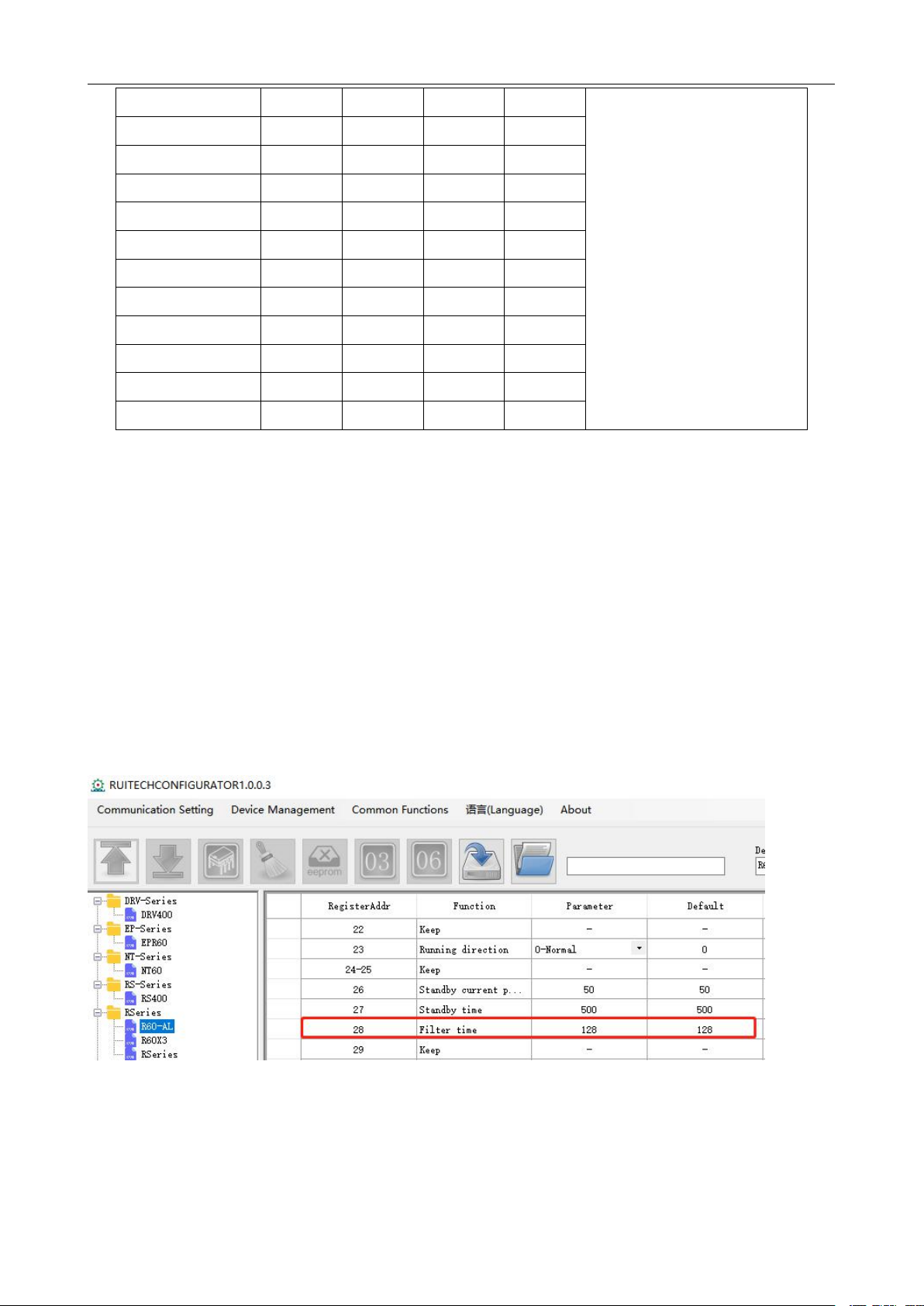
4.4 Pulse command filtering....................................................................................................................... 6
4.5 The setting of pulse mode....................................................................................................................7
5. Driver working status LED indication........................................................................................................7
6. Phase loss alarm......................................................................................................................................... 7
7. Internal motion control function................................................................................................................. 7
7.1 Communication control mode..............................................................................................................8
7.1.1 Point control mode......................................................................................................................... 8
7.1.2 Jog control mode............................................................................................................................9
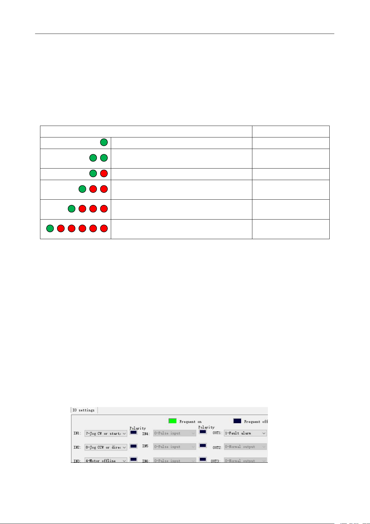
7.2 IO Control: Start and Stop + Direction............................................................................................. 10
7.3 IO Control: Forward + Reverse......................................................................................................... 11
8. Common faults and troubleshooting.......................................................................................................12
9. Guarantee clause...................................................................................................................................... 12

3R110 Plus User Manual
szruitech.com
1
1. Product overview
R110-PLUS is a high-voltage digital two-phase stepper motor driver with integrated intelligent
motion controller functions and built-in S-shaped acceleration and deceleration commands.
Through the USB port, it is convenient to configure the driver and expand the application of the
driver.
1.1 Characteristic
Working voltage:110~220VAC
Communication:USB to COM
Maximum phase current output: 7.2A/Phase (Sinusoidal Peak)
PUL+DIR/CW+CCW pulse mode optional
Phase loss alarm function
Half-flow function
Digital IO port:
3 photoelectric isolation digital signal input, high level can directly receive 24V DC level;
1 photoelectric isolation digital signal output, maximum withstand voltage 30V, maximum input
or pull-out current 50mA.
8 gears can be customized by users
16 gears can be subdivided by user-defined subdivision, supporting arbitrary resolution in the
range of 200-65535
IO control mode, support 16 speed customization
Programmable input port and output port
2. Application environment and installation
2.1 Environmental requirement
Item
Rtelligent 3R110-PLUS
Installation environment
Avoid dust, oil and corrosive environment
Vibration
0.5G(4.9m/s2)Max
Operating temperature/humidity
0℃~ 45 ℃/ 90% RH or less (no
condensation)
Storage and transportation temperature:
-10℃~ 70℃
Cooling
Natural cooling / away from the heat source
Waterproof grade
IP54

3R110 Plus User Manual
szruitech.com
2
2.2 Driver installation dimensions
3. Driver port and connection
3.1 Power supply and motor port function description
Function
Grade
Definition
Remarks
Power supply
PE
Single-phase 220VAC power
input
AC
AC
Motor
PE
Motor PE earth wire
Reversing any two wires of
U, V, W, which can make the
motor run in the opposite
direction
NC
Dangling
W
V
Three phase stepper motor
U

3R110 Plus User Manual
szruitech.com
3
3.2 Control signal connection
Function
Grade
Description
Pulse /IN1
PUL+
The control signal is 5 ~ 24V
compatible. No additional current
limiting resistor is required.
PUL-
Direction /IN2
DIR+
DIR-
Enable /IN3
ENA+
ENA-
Alarm /OUT1
ALM+
Optocoupler isolation, open collector
output
ALM-
3.2.1 PUL, DIR port(IN1,IN2)
By default, when operating in external pulse command mode, 3R110-PLUS can receive two pulse
command signals: PUL+DIR, CW+CCW.
Pulse and direction (PUL + DIR)
Double pulse (CW +CCW)
The command form of the external pulse is set by the debugging software:
Set by DIP switch 10
SW10 = OFF, PUL+DIR
SW10 = ON, CW+CCW
Forward
Reverse
Reverse
Forward

3R110 Plus User Manual
szruitech.com
4
3.2.2 ENA(IN3)port
The default ENA port is the driver offline (enable) function:
When the internal optocoupler is off, the driver outputs current to the motor;
When the internal optocoupler is on, the driver will cut off the current of each phase of the motor to
make the motor free, and the step pulse will not be responded.
When the motor is in an error state, it is automatically turned off. The level logic of the enable signal
can be set to the opposite.
At the same time, this port can be reused as other functions like IN1 and IN2.
3.2.3 ALM(OUT1)port
The driver includes an optically isolated output port ALM. By default, the ALM port is an alarm output
port. When the driver is in an error state and normal operation, the ALM port outputs different
optocoupler levels.
It can also be reused for other functions, as shown below:
3.3 USB port
The USB is a micro usb connector and requires a USB bridge.

3R110 Plus User Manual
szruitech.com
5
4. The setting of DIP switches and operating parameters
The setting of current Standby current The setting of pulse per revolution Filtering Pulse mode
4.1 The setting of current
Sine peak A
SW1
SW2
SW3
Remarks
2.3
on
on
on
User can set 8 levels of
current through debugging
software
3.0
off
on
on
3.7
on
off
on
4.4
off
off
on
5.1
on
on
off
5.8
off
on
off
6.5
on
off
off
7.2
off
off
off
4.2 Standby current
SW4 is used to set the current percentage of the driver when it is in standby.
SW4 = ON, as long as the driver is in the enabled state, the current remains at the set current
SW4 = OFF. After the driver stops receiving pulses for a certain time, it enters the standby state,
and the current drops to a certain percentage of the set current.
The default setting is: 1 second after stopping receiving the pulse, the motor winding current will be
50%.
4.3 The setting of pulse per revolution
Set the pulse per revolution required by the motor. Due to digital control, the number of subdivisions
can be set to any number between 200 and 65535.
Steps/revolution
SW5
SW6
SW7
SW8
Remarks
7200
on
on
on
on
Users can set up 16 level
subdivision through debugging
software.
400
off
on
on
on
800
on
off
on
on
1600
off
off
on
on
SW1
SW2
SW3
SW4
SW5
SW6
SW7
SW8
SW9
SW0

3R110 Plus User Manual
szruitech.com
6
3200
on
on
off
on
6400
off
on
off
on
12800
on
off
off
on
25600
off
off
off
on
1000
on
on
on
off
2000
off
on
on
off
4000
on
off
on
off
5000
off
off
on
off
8000
on
on
off
off
10000
off
on
off
off
20000
on
off
off
off
25000
off
off
off
off
4.4 Pulse command filtering
The driver has a built-in pulse command smoothing function, which can make the motor start more
stable.
SW9 = ON, enable pulse command filtering
SW9 = OFF, disable pulse command filtering
The default command filter time is 512*61us=31ms
Command filtering can smooth the motor movement, but also introduces lag. The user needs to
choose whether to enable this function according to the actual situation.The filter time can be set by
the debugging software:

3R110 Plus User Manual
szruitech.com
7
4.5 The setting of pulse mode
SW10 is used to set the form of the driver receiving pulse.
SW10 = OFF, pulse + direction mode
SW10 = ON, CW+CCW double pulse mode
5. Driver working status LED indication
LED status
Driver status
Green indicator is on for long time
Driver not enabled
Green indicator is flickering
Driver working
normally
One green indicator and one red indicator
Driver overcurrent
One green indicator and two red indicators
Driver input power
overvoltage
One green indicator and three red indicators
The internal voltage of
the driver is wrong
One green indicator and seven red
indicators
Motor lose phase
6. Phase loss alarm
The driver has a motor phase loss alarm function, which can detect the phase loss state of the
motor during stationary and movement. During the operation of the stepper motor, due to
mechanical reasons, the winding wire of the motor may be loosened and disconnected. At this time,
the driver will output an alarm signal to prevent the device from making an erroneous action.
Since this function relies on the current detection of the motor windings, this function has a false
alarm when the motor current is too small (less than 300 mA). At this point, the user can turn off this
function. In the parameter management and setting interface of the debugging software, set
parameter No. 188(phase loss detection enable) to 0.
7. Internal motion control function
When working in the internal pulse command mode, the PUL and DIR ports are used as IO input signals.
The IO function needs to be set through the debugging software. As shown below:

3R110 Plus User Manual
szruitech.com
8
7.1 Communication control mode
In this mode, the user can make the motor run the specified pulse stroke or jog operation by
communicating the given operation command.
In internal pulse mode, the motor is controlled by register 18
0:Waiting state.
The driver receives any control command and will resume the waiting state after the driver
processes it. So reading this register always returns 0.
1:Fixed length forward rotation.
In the relative position mode, the motor runs in the forward direction according to the 70 ~74
register parameters.
In the absolute position mode, the operation state is determined according to the current position
and the absolute position set by 70~74.
2:Fixed length reverse rotation.
In the relative position mode, the motor runs in the reverse direction based on the 70~74 register
parameters.
In the absolute position mode, the operation state is determined according to the current position
and the absolute position set from 70 ~74.
3:Speed mode, continuous forward rotation.
According to 75 and 76 registers, the motor runs at forward acceleration.
4:Speed mode, continuous reverse.
According to 75 and 76 registers, the motor runs at reverse acceleration.
5:Emergency stop
According to the 77 register, the motor decelerates and stops.
6:Slow down and stop.
In position mode, the motor decelerates and stops according to the 71 register
In speed mode, the motor decelerates and stops according to the 76 register
Others: no effect.
7.1.1 Point control mode
The communication controls the function of the motor to run the specified pulse stroke. The specific
modes and parameters to be set are as follows (register addresses are not specified or specified as
decimal numbers):
(1) Set the value of register address 20 (preset application selection in internal pulse mode) to
0(Communication control, respond to the command of register address 18)

3R110 Plus User Manual
szruitech.com
9
(2) Set the function of the digital input and output port according to the application requirements and
the actual wiring terminals;
(3) Set the motion parameters:
Address
Unit
Parameter Description
70
R/S^2
Acceleration of point motion
72
RPM
Speed of point motion
73
Command
pulse
The number of command pulses for point motion is lower
than the 16-bit register
74
Command
pulse
The number of command pulses for point motion is high
16-bit register
78
R/S^2
Emergency stop deceleration
84
-
Set position operation mode:
0: incremental 1: Absolute
(4) Communication given operation command: start the point movement by writing the values “1”
(fixed length forward rotation) and “2“(fixed length reverse rotation) to register 18.(For details on
this register, please see "Driver Control Mode" Set register 18 in [17~23]";
(5) During operation, if need to stop, please write value “6“(deceleration to stop, deceleration is
the setting value of register 71) and value “5”(emergency stop, deceleration is the setting value
of register 78) to register 18 .
Note:
When the motor is in operation, it only responds to the stop command (deceleration stop or
emergency stop). If it is necessary to change the running direction of the motor by command,
please send the stop command to wait for the motor to stop, and then send the start signal of the
other direction.
The acceleration (register 70), deceleration (register 71), and speed (register 72) are changed
during motor operation, but the driver will not respond to these set values immediately. It will not run
at the set values until the motor is stopped and restarted.
It is important to note that the emergency stop deceleration (Register 78) is responded to during the
current sport emergency stop, without waiting for the next stop of the emergency stop.
7.1.2 Jog control mode
3R110Plus has the function of controlling the jog operation of the motor through communication.The
specific modes and parameters to be set are as follows (register addresses are not specified or
specified as decimal numbers):
(1) Set the value of register address 20 (preset application selection in internal pulse mode) to
0(Communication control, respond to the command of register address 18)
(2) Set the function of the digital input and output port according to the application requirements and
the actual wiring terminals;

3R110 Plus User Manual
szruitech.com
10
(3) Set the motion parameters:
Address
Unit
Parameter Description
75
R/S^2
Acceleration of jog motion
76
R/S^2
Deceleration of jog motion
77
RPM
Speed of jog motion
78
R/S^2
Emergency stop deceleration
(4) Communication given operation command: Start jog movement by writing values 3 (continuous
forward rotation) and 4 (continuous reverse rotation) to register 18.(For details on this register,
please see "Drive Control Mode" Set register 18 in [17~23]";
(5) During operation, if need to stop, please write value “6 “(deceleration to stop, deceleration is the
setting value of register 76) and value “5” (emergency stop, deceleration is the setting value of
register 78) to register 18 .
Note:
When the motor is in operation, it only responds to the stop command (deceleration stop or
emergency stop). If it is necessary to change the running direction of the motor by command,
please send the stop command to wait for the motor to stop, and then send the start signal of the
other direction.
The acceleration (register 75) and deceleration (register 76) are changed during motor operation,
but the driver will not respond to these set values immediately. It will not run at the set values until
the motor is stopped and restarted.
It is important to note that the emergency stop deceleration (Register 78) is responded to during the
current sport emergency stop, without waiting for the next stop of the emergency stop.
The speed (register 77) can be changed during the operation of the motor, and the driver will
respond immediately, that is, the motor will run at the set speed value immediately, without stopping
and restarting to respond.
7.2 IO Control: Start and Stop + Direction
With this mode, two IN terminals are used to control the operation of the motor. One IN terminals is
used to control the start/stop of the motor, and the other IN terminal is used to control the running
direction of the motor. The specific settings are as follows:
(1)Command mode: 0 - internal pulse mode
(2)Internal application mode: 2 –IO speed control: start and stop + direction

3R110 Plus User Manual
szruitech.com
11
(3)IO settings:
(4)This mode is for the speed defined by the speed table, selected by SW5, 6, 7, 8.
(5)Set the motion parameters, you can modify the acceleration, deceleration
7.3 IO Control: Forward + Reverse
Same as 7.2, only need to change (2) to: 3 –IO speed control: forward + reverse.

3R110 Plus User Manual
szruitech.com
12
8. Common faults and troubleshooting
Phenomenon
Possible situations
Solutions
Motor does
not work
Power indicator is off
Check the power supply circuit for normal
power supply
The motor rotor is locked but the
motor does not work
Pulse signal is weak; increase the signal
current to 7-16mA
The speed is too slow
Select the right micro-stepping
Driver is protected
Solve the alarm and re-power
Enable signal problem
Pull up or disconnect the enable signal
Command pulse is incorrect
Check whether the upper computer has
pulse output
The steering
of motor is
wrong
The rotary direction of motor is
reverse
Adjust the DIP SW5
The motor cable is disconnected
Check the connection
The motor has only one direction
Pulse mode error or DIR port damaged
Alarm
indicator is on
The motor connection is wrong
Check the motor connection
The voltage is too high or too low
Check the power supply
The position
or speed is
wrong
The signal is disturbed
Eliminate interference for reliable
grounding
The command input is incorrect
Check the upper computer instructions to
ensure the output is correct
The setting of Pulse per
revolution is wrong
Check the DIP switch status and correctly
connect the switches
Encoder signal is abnormal
Replace the motor and contact the
manufacturer
The Driver
terminal
burned up
Short circuit between terminals
Check power polarity or external short
circuit
Internal resistance between
terminals is too large
Check whether there is any solder ball
due to excessive addition of solder on the
wire connections
9. Guarantee clause
9.1 Warranty period: 12 months
We provide quality assurance for one year from the date of delivery and free maintenance service
for our products during the warranty period.
9.2 Exclude the following:
■ Improper connection, such as the polarity of the power supply is reversed and insert/pull the
motor connection when the power supply is connected.
■ Beyond electrical and environmental requirements.
■ Change the internal device without permission.

3R110 Plus User Manual
szruitech.com
13
9.3 Maintenance process
For maintenance of products, please follow the procedures shown below:
(1) Contact our customer service staff to get the rework permission.
(2) The written document of the Driver failure phenomenon is attached to the goods, as well as the
contact information and mailing methods of the sender.
Mailing address:
Post code:
Tel.:
Table of contents
Other Rtelligent DC Drive manuals