Rtelligent EC Series User manual

ECR60/ECT60 User manual
1
ECR60/ECT60
User manual
Shenzhen ReitE Electrical and Mechanical Technology Co., Ltd.

ECR60/ECT60 User manual
1
第一章 Drive description
1.1 Product introduction
Thank you for choosing the Reiter EC series stepper motor driver. The EC Series is a
high-performance bus-controlled stepper motor driver with the ability to integrate
intelligent motion controllers. The EC Series EtherCAT drives can be operated as
standard EtherCAT slaves and support CoE (CANopen over EtherCAT).
The ECR60 is open-loop control and the ECT60 is closed-loop control.
Characteristics
⚫Operating voltage DC: 24 to 80V
⚫Support for CoE (CANopen over EtherCAT), CiA 402 compliant
⚫Support for CSP, PP, PV, Homing mode
⚫Minimum sync period 500us
⚫Double-mouthEd RJ45 connector for EtherCAT communications
⚫Maximum phase current output: 6A/phase (sine peak)
⚫Control methods: open-loop control, closed-loop control, FOC control
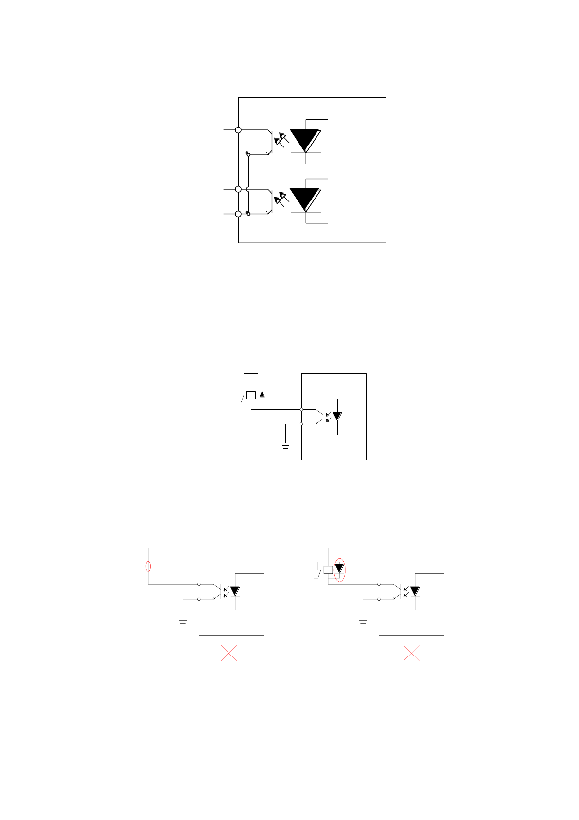
⚫Digital IO port:
6-way photoelectric isolation of digital signal input: IN1,IN2 for 5V differential input, can
also be connected to 5V single-ended input, IN3toIN6 for 24Vsingle-ended input, total
anode method;
2-way photoelectric isolation of digital signal output, maximum resistance voltage of

ECR60/ECT60 User manual
2
30V, maximum infusion or pull-out current 100mA, common cathode docking method.
Electrical characteristics
ECR60 Electrical characteristics
Product model
ECR60
ECT60
Output current
0.5 to 6A
Supply voltage
24 to 80VDC
Matching motors
Below 86 base
Encoder interface
No
Incremental orthogonal encoder, 4x
Encoder resolution
No
1000 to 65535 pulses/revolution
Photoelectric
isolation input
6 way : 2 way 5V differential input,
4 road common anode 24V input
4-way common anode 24V input
Photoelectric
isolation output
2-way photoelectric isolation output: alarm, lock, in place and universal
output
Communication
interface
RJ45
Do not exceed the scope of use described above.

ECR60/ECT60 User manual
3
1.2 Power and motor
Identity
Description
V-plus
DC-powered, positive, V-connected power supply negative. The voltage is 24 to
80VDC. Due to the effect of the anti-electric potential, the customer needs to
reserve a certain amount of voltage margin when using
V-
A-plus
Two-phase stepper motor winding interface
Any pair of A-plus, A--
A-
B-plus
B-
Connecting the power supply
Connection driver and DC power supply: Positive, V-DC power negative
Ensure a reliable connection between the drive base and the earth with a ground screw
ECR60 power range of 24 to 80VDC, pay attention to the positive and negative polarity
of the power supply
Connecting the motor
If you are using a rite-hit stepper motor, connect the black, green, blue, and red four
wires in turn to the a-plus, A-, B-, B-ports of the drive.
Connection encoder
This feature is limited to ECT60 products. The ECT60 is fixed using IN1plus/IN1-
andIN2plus/IN2- as the encoder input interface.
The connection of the particular encoder needs to be based on the motor
manufacturer's instructions.

ECR60/ECT60 User manual
4
1.3 Digital input and output ports
The ECR60 stepper driver has 6 photoelectric isolated digital inputs and2 photoelectric
isolated digital ports.
ECT60 Because IN1 and IN2 are assigned to orthogonal encoder interfaces, they can no
longer be used for other input port functions and will not work for in1, IN2 functional
settings.
Digital input port
The ECR60 step driver has 6 digital inputs and2 digital outputs. The object dictionary
0x2007 is the functional setting for the input port,and0x2008 is the polarity setting
for the input port.
Note: IN1s/IN1-,IN2s/IN2- is a 5V input terminal, do not directly connect the input signal
above this voltage, as this will cause damage to the driver!
The schematic of the input port is shown below, and the user can wire the system
according to the schematic.

ECR60/ECT60 User manual
5
IN1plus/IN1-, IN2 plus /IN2- differential input terminals
IN1,IN2 is reserved external motor encoder, constitutes a closed-loop system, ECR60 can
not receive encoder signal. ECT60 is only allowed.
5V differential input
5V single-ended input
驱动器
+24V
IN1
IN2
IN3
IN4
IN5
IN6
驱动器
OUT1
OUT2
OUT3
OUT4
0V
NR60-6IN数字IO口接线端子示意图
驱动器
+24V
IN1
IN2
IN3
IN4
驱动器
OUT1
OUT2
0V
NR60-4IN数字IO口接线端子示意图
驱动器
IN1+
IN1-
IN2-
IN3
IN4
IN5
IN6
NT60 数字IO接线端子示意图
IN2+
+24V
驱动器
OUT1
OUT2
0V
伺服驱动器
脉冲输入接口电路
PULSE+
PULSE-
SIGN+
SIGN-
伺服驱动器
PULSE+
PULSE-
SIGN+
SIGN-
DC5V
上位控制器
脉冲的单端驱动
伺服驱动器
PULSE+
PULSE-
SIGN+
SIGN-
DC24V
上位控制器
脉冲的单端驱动
2K
2K
IN1+
IN1-
IN2+
IN2- IN2-
IN2+
IN1-
IN1+
IN1+
IN1-
IN2+
IN2-

ECR60/ECT60 User manual
6
Note: When the IN1 and IN2 ports use the 24V input, please string the2K limiting
resistance externally, otherwise the drive will be damaged.
IN3to IN6 single-ended input terminals
Taking IN3 as an example, the IN3toIN6 interface circuits are the same.
When the upper unit is the relay output:
When the upper unit is an open output for the collector:
伺服驱动器
脉冲输入接口电路
PULSE+
PULSE-
SIGN+
SIGN-
伺服驱动器
PULSE+
PULSE-
SIGN+
SIGN-
DC5V
上位控制器
脉冲的单端驱动
伺服驱动器
PULSE+
PULSE-
SIGN+
SIGN-
DC24V
上位控制器
脉冲的单端驱动
2K
2K
IN1+
IN1-
IN2+
IN2- IN2-
IN2+
IN1-
IN1+
IN1+
IN1-
IN2+
IN2-
伺服驱动器
脉冲输入接口电路
PULSE+
PULSE-
SIGN+
SIGN-
伺服驱动器
PULSE+
PULSE-
SIGN+
SIGN-
DC5V
上位控制器
脉冲的单端驱动
伺服驱动器
PULSE+
PULSE-
SIGN+
SIGN-
DC24V
上位控制器
脉冲的单端驱动
2K
2K
IN1+
IN1-
IN2+
IN2- IN2-
IN2+
IN1-
IN1+
IN1+
IN1-
IN2+
IN2-
伺服驱动器
数字输入接口电路
外部+24VDC
外部GND
继电器
伺服驱动器
数字输入接口电路
外部+24VDC
外部GND
伺服驱动器
数字输入接口电路
外部+24VDC
外部GND
NPN
COM+
IN1
COM+
IN1
COM+
IN1
PNPPNP

ECR60/ECT60 User manual
7
Note: PNP input is not supported
伺服驱动器
数字输入接口电路
外部+24VDC
外部GND
继电器
伺服驱动器
数字输入接口电路
外部+24VDC
外部GND
伺服驱动器
数字输入接口电路
外部+24VDC
外部GND
NPN
COM+
IN3
COM+
IN3
COM+
IN1
PNPPNP

ECR60/ECT60 User manual
8
Digital output port
The ECR60/ECT60 contains two photoelectric isolation output signals.
OUT1 has an output current capacity of 30mA.
OUT2 has an output current capacity of 150mA.
The digital output port is all normally open by default, the function of the output port
can be selected by object dictionary 2005, and the object dictionary 2006 is used to set
the polarity of the set output port.
Object
dictionary
Name
Proper
ty
Type
Range
The
default
value
Unit
Note
0x2005:01
Output Port
1 Function
R/W/S
UINT
0 to 3
1
---
Output port feature
selection:
0 - Custom output
1 - Alarm output
2 - Holding gate
output
3 - Output in place
0x2005:02
Output port
2 function
R/W/S
UINT
0 to 3
2
---
0x2006
Output port
polarity
settings
R/W/S
UINT
0 to 3
3
---
Set the normally open,
normally closed
feature of the output
port
0 - Often closed
1 - Always open

ECR60/ECT60 User manual
9
Take OUT1 as an example, the OUT1to OUT2 interface circuit is the same.
When the upper unit is entered for a relay:
Correct wiring diagram:
Error wiring diagram:
When the upper unit is optically coupled input:
驱动器
+24V
IN1
IN2
IN3
IN4
IN5
IN6
驱动器
OUT1
OUT2
OUT3
OUT4
0V
NR60-6IN数字IO口接线端子示意图
驱动器
+24V
IN1
IN2
IN3
IN4
驱动器
OUT1
OUT2
0V
NR60-4IN数字IO口接线端子示意图
驱动器
IN1+
IN1-
IN2-
IN3
IN4
IN5
IN6
NT60 数字IO接线端子示意图
IN2+
+24V
驱动器
OUT1
OUT2
0V
DC12-24V
继电器
伺服驱动器
外部地
输出电路外接继电器
DC12-24V 伺服驱动器
外部地
DC12-24V 伺服驱动器
外部地
OUT1
DG
DC12-24V
光耦
伺服驱动器
外部地
输出电路外接光耦
OUT1
DG
继电器
未接入继电器 续流二极管极性错误
DC12-24V
光耦
伺服驱动器
外部地
OUT1
DG
未接入限流电阻
DC12-24V
继电器
伺服驱动器
外部地
输出电路外接继电器
DC12-24V 伺服驱动器
外部地
DC12-24V 伺服驱动器
外部地
OUT1
DG
DC12-24V
光耦
伺服驱动器
外部地
输出电路外接光耦
OUT1
DG
继电器
未接入继电器 续流二极管极性错误
DC12-24V
光耦
伺服驱动器
外部地
OUT1
DG
未接入限流电阻

ECR60/ECT60 User manual
10
DC12-24V
继电器
伺服驱动器
外部地
输出电路外接继电器
DC12-24V 伺服驱动器
外部地
DC12-24V 伺服驱动器
外部地
OUT1
DG
DC12-24V
光耦
伺服驱动器
外部地
输出电路外接光耦
OUT1
DG
继电器
未接入继电器 续流二极管极性错误
DC12-24V
光耦
伺服驱动器
外部地
OUT1
DG
未接入限流电阻

ECR60/ECT60 User manual
11
1.4 Connect etherCAT
Use cat5E (or higher) network cables.
The Ethernet input inn IN is connected to the Ethernet output interface OUT of the
controller or the previous driver on the bus. The Ethernet output interface OUT is
connected to the Ethernet input inthe for the next driver on the bus. If the drive is the
last node on the bus, only the Ethernet input IN needs to be connected.
EtherCAT status indicator
The yellow light of RJ45 is used in the Link state to indicate whether there is a network
connection.
The green light for RJ45 is used for the Activity status, indicating whether there is data
communication.
RUN/ERR LED:
Led
Color
State
Describe
RUN
Green
Not on
initialization state
Slow flash
pre-operational state
Single flash
safe-operational state
Always bright
operational state
Err
Red
Not on
No errors
Slow flash
General errors
Single flash
Sync error
Double Flash
Watchdog mistake
Flash: 50ms, 50ms (10Hz). So loop.

ECR60/ECT60 User manual
12
Slow flash: 200ms, 200ms (2.5Hz). So loop.
Single flash: 200ms, 1s. So loop.
Double flash: bright 200ms, 200ms, 200ms, 1s. So loop.

ECR60/ECT60 User manual
13
1.5 EtherCAT site address
The EC series supports two ways to set the slave address: the object dictionary 0x2150
set the site alias and the ESC set site alias, and selected by the object dictionary 0x2151.
The default 0x2151 is 0, and the node address is allocated through the master and saved
to EEPROM.
When the user needs to set a fixed address on their own, they need to set 0x2151 to 1
and then write the desired address value in 0x2150.
0x2151
0x2150
Site address
0
1001
Master configuration site alias to ESC EEPROM 0x0004 word address
1
Set a
value
Object dictionary 2150 set value is node address value
1.6 Alarm code
LED status
Drive status
The green
light is on.
Drive does not enable
Flashing green
light
Drive works
1 green, 1 red
Drive Overcurrent
1 green, 2 red
Drive input power
overvoltage
1 green, 3 red
There was an error in the
voltage inside the driver
1 green, 4 red
Encoder variance alarm
1 green, 6 red
Parameter check error

ECR60/ECT60 User manual
14
1.7 Mechanical size

ECR60/ECT60 User manual
15
第二章 Parameter description and settings
2.1 General use parameter
0x1000 Unit Type
Object Type
Data Type
Access Type
PDO Mapping
Default Value
Var
UNSIgned
Ro
NO
0x00040192
Bit 0-15: Device profile number 0x0192: CiA402
Bit 16-31: Additional information 0x0004: Stepper Drive
0x1001 Appliance Name
Displays the current drive model name.
The ECR60-42 function, like the ECR60, only limits the default current of the driver,
preventing the user from matching the small motor, without the first time to modify the
current of the driver resulting in excessive current, damage to the driver and the motor.
On 0x1001, both show "ECR60"
Object Type
Data Type
Access Type
PDO Mapping
Default Value
Var
Visible string
Ro
NO
ECR60
ECT60
Object Type
Data Type
Access Type
PDO Mapping
Default Value
Var
Visible string
Ro
NO
ECT60
0x1009 Hardware Version
Object Type
Data Type
Access Type
PDO Mapping
Default Value
Var
Visible string
Ro
NO
0xA1
0x100A Software Version
Object Type
Data Type
Access Type
PDO Mapping
Default Value
Var
Visible string
Ro
NO
0x101A

ECR60/ECT60 User manual
16
Save parameters
Sub-index of object dictionary 0x1010: 01 writes 1, which saves the current parameter.
When saving the parameters, stop the motor first, and then save the parameters.
The data structure is as follows:
Index
Sub-index
Name
PDO mapping
The default value
1010
00
Maximum
number of sub-
indexes
No
1
01
Save parameters
No
0
Restore factory settings
Sub-index of object dictionary 0x1011: 01 writes to 1, then poweres on again to restore
the drive to factory state.
When factory settings are restored, stop the motor first, and then save the parameters.
Index
Sub-index
Name
PDO mapping
The default value
1011
00
Maximum
number of sub-
indexes
No
1
01
Save parameters
No
0

ECR60/ECT60 User manual
17
2.2 Manufacturer-specific objects
0x2000 operating current
Object
dictionar
y
Name
Propert
y
Type
Range
The default
value
Unit
0x2000
Peak Current
R/W/S
UINT
100 to 6000
3000
mA
The object is used to set the sine peak current for the run of the stepper motor open
ring.
0x2001 segmentation/resolution
Object
dictionar
y
Name
Propert
y
Type
Range
The default
value
Unit
0x2001
Motor Resolution
R/W/S
UINT
200 to65535
10000
Pulse/rev
This object is used to set the number of pulses required for the motor to run a circle
while the stepper motor is running.
The ECT60 operates in closed-loop mode by default, where the number of pulses
required for the motor to run a circle is set by the 0x2020 encoder resolution.
0x2002 Standby Time
Object
dictionar
y
Name
Propert
y
Type
Range
The default
value
Unit
0x2002
Idle Time
R/W/S
UINT
200 to65535
500
Ms
This object is used to set the time when the stepper motor is in standby when it stops
running.
0x2003 Standby Current Percentage
Object
dictionar
Name
Propert
y
Type
Range
The default
value
Unit

ECR60/ECT60 User manual
18
y
0x2003
Idle Current Percent
R/W/S
UINT
0to100
50
%
This object is used to set the percentage of the operating current set by 0x2000 when
the motor stops running into standby when the motor is in standby while running on
the ring of the stepper motor.

ECR60/ECT60 User manual
19
0x2005 output port function
Object
dictionary
Name
Propert
y
Type
Range
The default
value
Unit
0x2005:01
Output 1 Function
R/W/S
UINT
0 to 3
1
---
0x2005:02
Output 2
Function
R/W/S
UINT
0 to 3
2
---
The ECR60 contains two output ports, which are used to set the corresponding function
of the output port.
The port functionality is defined as follows:
Value
Function
0
Custom output
1
Alarm output
2
Holding gate output
3
Output in place
When set to custom output, the state of the port can be controlled by the polarity
setting of 0x2006.
0x2006 output port polarity
Object
dictionary
Name
Propert
y
Type
Range
The default
value
Unit
0x2006
Outputs Polarity
R/W/S
UINT
0to3
3
---
Set the normally open and normallyclosed characteristics of the output port:Bit0 is the
output port 1 polarity setting, bit1 is the output port 2 polarity setting.
0 - Often closed
1 - Always open
Bit15 to bit2
Bit1
Bit0
---
OUT2
OUT1
This manual suits for next models
2
Table of contents
Other Rtelligent DC Drive manuals
Popular DC Drive manuals by other brands

Piezoconcept
Piezoconcept TT2 Installation and operation manual

Lenze
Lenze EZAELN3 Series Mounting instructions

ABB
ABB ACQ550-U1-015A-4 Series user manual

Just Motion Control
Just Motion Control 2DM556 manual

Danfoss
Danfoss VLT HVAC Drive FC 102 operating instructions

BONFIGLIOLI
BONFIGLIOLI Act 201 operating instructions