manuals.online logo
Brands
  1. Home
  2. •
  3. Brands
  4. •
  5. Elmdene
  6. •
  7. Power Supply
  8. •
  9. Elmdene G1380 BMU-y Series User manual

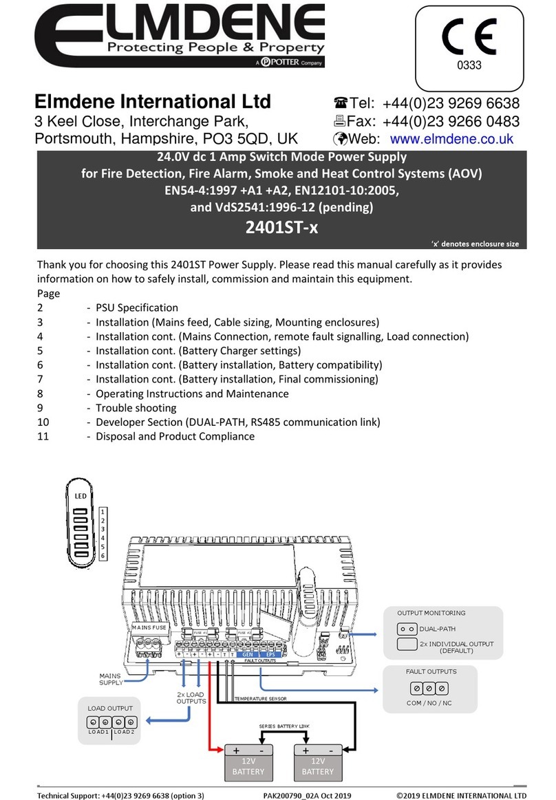
Elmdene G1380 BMU-y Series User manual

Technical Support Line +44 (0)23 9269 6638 (Option 3) G1380xB -y-s PAK200744_01C ay 2017 © 2017 Elmdene International Ltd
13.8V
DC
S
WITCH
M
ODE
P
OWER
S
UPPLY
M
ODULE
W
ITH
B
ATTERY
ONITORING AND
R
E OTE
F
AULT
S
IGNALLING
Models:
G1380xBMU y
Where ‘x’ is max load current: 3A, 4A or 5A
Where ‘y’ is the number of outputs
F
EATURES
High efficiency cost effective power supply range ideal for use in Intruder, Access Control and General
Security applications. Featuring a regulated 13.8V dc output supplying continuous full rated current to load
and a universal mains voltage input. aximum battery life is assured using deep discharge protection to
prevent premature battery failure when operating in standby mode for extended periods. Two sets of volt
free contacts are provided to signal (i) loss of mains and (ii) battery and loss of output faults.
•Continuous full rated current to load
•Universal mains input voltage 90-264V ac
•High efficiency electronics for reduced
running costs and lower operating
temperatures
•Installer safe design with all high voltage
electronics fully shrouded
•Green ains present LED
•Red Fault diagnostic LED
•Volt free contact signalling mains failure (EPS)
•Volt free contact signalling output and battery
faults (GEN)
•Full electronic short circuit and overload
protection on load output under mains
operation
•Individual battery and output fuse protection
•ains transient protection circuit
S
PECIFICATION
Input Specification
Voltage (rated) 100-240V ac
Voltage (operating) 90-264V ac
Frequency 50-60Hz
ax Current See odel Specification Table
ains Input Fuse See odel Specification Table
Output Specification
Voltage 13.5– 14.2V dc (13.8V dc nominal) on mains power
10 – 12.3V dc on battery standby
ax load current See odel Specification Table
Ripple < 150 mV pk-pk max
Load output Fuse See odel Specification Table below
Overload Electronic shutdown until overload or short circuit removed
(under mains power only)
Elmdene International Ltd
Tel: +44 (0)23 9269 6638
3 Keel Close, Interchange Park, Fax: +44 (0)23 9266 0483

Portsmouth,
Hampshire
,
PO3 5QD
, UK

Web:
www.elmdene.co.uk
Technical Support Line +44 (0)23 9269 6638 (Option 3) G1380xB -y-s PAK200744_01C ay 2017 © 2017 Elmdene International Ltd
Mechanical
Product Reference G13803BMU y G13804BMU y G13805BMU y
Dimensions w x h x d (mm) 152 x 71 x 106
Environmental
Temperature -10 to +40°C (operating) 75% RH non-condensing
-20 to +80°C (storage)
Standby Battery
Battery Type 12V Valve Regulated Lead Acid
Battery Charging Fuse protection See below table
Model Specification Table
G13803BMU 4 G13804BMU 4 G13805BMU 4
Max Output Current to load 3A 4A 5A
Output Fuse (20mm glass) F3.0A 4 X
F0.8A F4.0A 4 x
F1.0A F5.0A 4 X
F1.25A
Max Mains Input Current < 2.0A @ 90V ac < 2.0A @ 90V ac < 3.0A @ 90V ac
Mains Input Fuse (20mm HBC) T3.15A T3.15A T3.15A
Battery Fuse Protection F3.0A F4.0 A F5.0A
S
IGNALLING
O
UTPUTS
GEN Fault (general) 0.1A @ 60V dc N/O volt free contact. Open when battery
disconnected, *output fuse fail, battery fuse fail or output short
circuit.
EPS Fault (mains) 0.1A @ 60V dc N/O volt free contact.
Open when loss of mains for more than 10s
Fault Diagnostic Table:
Red LED
(Fault)
Green LED
(Mains) PSU Status
OFF ON Normal: Battery fully charged
One short flash
every second ON Normal: Battery charging but not fully charged
Flashing:
1second On
1 second Off
ON Fault: Output fuse or battery fuse blown, or battery missing
OFF Fault: No mains, output fuse blown
One short flash
every 3 seconds OFF Fault: No mains, battery supplying load.
OFF OFF Fault: No mains, No output, Batteries disconnected or completely
discharged
C
ONNECTIONS
O/P +, - Connection to equipment to be powered (observe polarity)
EPS Fault: Relay output for mains fail. Open if loss of mains.
GEN Fault: Relay output for General Fault. Open in fault condition
BATT +, - Connection to standby battery. Use cables provided (observe polarity)
Technical Support Line +44 (0)23 9269 6638 (Option 3) G1380xB -y-s PAK200744_01C ay 2017 © 2017 Elmdene International Ltd
I
NSTALLATION
I
NSTRUCTIONS
This unit is only suitable for installation as permanently connected equipment. This PSU is NOT SUITABLE for external
installation. This unit must be fed from a mains power source having a separate (approved) disconnect device and fitted
with a fuse or other over-current protection device rated at 3A maximum. Ensure that the disconnect device used has
appropriate earth fault protection to the applicable standard. EQUIPMENT MUST BE EARTHED. Before installation,
ensure that external disconnect device is OFF.The PSU should be installed according to all relevant safety regulations
applicable to the application
.
Mounting
1) ount securely in correct orientation allowing minimum clearance – see Fig. 1.0
2) Route mains and low voltage output cables via different knockouts and/or cable entry holes.
3)
Use bushes and cable glands rated to UL94 HB minimum.
Mains Power Up
4) Attach correctly rated mains cable (minimum 0.5mm
2
[3A], 300/500Vac). Fasten with cable ties.
5) Apply mains power.
Check for 13.8V dc on load outputs.
Check Green ains LED is ON.
6) Disconnect mains power.
Load Output
7) Attach correctly rated load cable and fasten using cable ties. Note polarity.
8) Apply mains power.
Check Green ains LED is ON.
NOTE: Red Fault LED may flash to indicate no battery has been connected, this is normal.
Verify load is operating correctly.
9) Disconnect mains power.
Signalling
10) Connect EPS and GEN fault outputs to appropriate inputs of Control and Indicating Equipment (CIE).
Standby Battery
11) Attach battery cables to terminal block and batteries.
NOTE: ensure correct polarity of battery connections: +ve use Red lead, ve use Black lead.
Fig 1.0 Mounting of Module
Technical Support Line +44 (0)23 9269 6638 (Option 3) G1380xB -y-s PAK200744_01C ay 2017 © 2017 Elmdene International Ltd
O
PERATING
I
NSTRUCTIONS
In the event of loss of mains, a battery fault or a GEN fault, the corresponding Fault signal contacts will open (see Fault
diagnostic table for LED indicator status).
If the output of the PSU fails, the cause of the failure should be investigated e.g. short circuit load, connection of a
deeply discharged battery. The fault should be rectified before restoring power to the PSU. If any of the fuses require
replacing, ensure the correct fuse rating and type is used.
M
AINTENANCE
This unit is intended for use by Service Personnel only. There are NO USER SERVICEABLE parts inside.
There is no regular maintenance required of the PSU other than periodic testing, and replacement of the standby
battery. Reference should be made to the battery manufacturer's documentation to determine typical expected
battery life with a view to periodic replacement of the battery.
C
OMPLIANCE
This power supply unit meets the essential requirements of the following European Directives:
Low Voltage 2014/35/EU
E C 2014/30/EU
WEEE 2012/19/EU
RoHs2 2011/65/EU
D
ISPOSAL OF
P
RODUCT AT
E
ND OF
L
IFE
This product falls within the scope of EU Directives 2012/19/EU Waste Electrical and Electronic Equipment (WEEE) and
2013/56/EU (Battery). At the end of life, the product must be separated from the domestic waste stream and disposed
via an appropriate approved WEEE disposal route in accordance with all national and local regulations.
Before disposal of the product, any batteries must be removed, and disposed separately via an appropriate approved
battery disposal route in accordance with all national and local regulations. Package used batteries safely for onward
transport to your supplier, collection point or disposal facility.
Caution: Risk of fire or explosion if bare battery wires are allowed to touch.
See Specification for battery type information. The battery is marked with the crossed out wheelie bin
symbol, which may include lettering to indicate cadmium (Cd), lead (Pb), or mercury (Hg).
For more information ee: www.recyclethi .info
The packaging upplied with thi product may be recycled.
Plea e di po e of packaging accordingly.

This manual suits for next models

3

Other Elmdene Power Supply manuals

Elmdene 2405STE User manual

Elmdene

Elmdene 2405STE User manual

Elmdene STX2401-MOD User manual

Elmdene

Elmdene STX2401-MOD User manual

Elmdene 2402STE User manual

Elmdene

Elmdene 2402STE User manual

Elmdene LPS-ENC-T Instruction Manual

Elmdene

Elmdene LPS-ENC-T Instruction Manual

Elmdene 20182423N User manual

Elmdene

Elmdene 20182423N User manual

Elmdene G240 N Series User manual

Elmdene

Elmdene G240 N Series User manual

Elmdene STX2402-MOD User manual

Elmdene

Elmdene STX2402-MOD User manual

Elmdene 2405ST Series User manual

Elmdene

Elmdene 2405ST Series User manual

Elmdene STX2405-E User manual

Elmdene

Elmdene STX2405-E User manual

Elmdene STX2402 Series User manual

Elmdene

Elmdene STX2402 Series User manual

Elmdene G2410BM-E User manual

Elmdene

Elmdene G2410BM-E User manual

Elmdene G2410BMU User manual

Elmdene

Elmdene G2410BMU User manual

Elmdene STX2401-C User manual

Elmdene

Elmdene STX2401-C User manual

Elmdene UNIVERSAL-12V-5A-M User manual

Elmdene

Elmdene UNIVERSAL-12V-5A-M User manual

Elmdene STX2405-MOD User manual

Elmdene

Elmdene STX2405-MOD User manual

Elmdene 2401ST User manual

Elmdene

Elmdene 2401ST User manual

Elmdene POE1230-C User manual

Elmdene

Elmdene POE1230-C User manual

Elmdene G1380xBM Series User manual

Elmdene

Elmdene G1380xBM Series User manual

Elmdene G1380xN-y-s Series User manual

Elmdene

Elmdene G1380xN-y-s Series User manual

Elmdene STX2410-H User manual

Elmdene

Elmdene STX2410-H User manual

Elmdene 2401ST User manual

Elmdene

Elmdene 2401ST User manual

Elmdene 2405ST Series User manual

Elmdene

Elmdene 2405ST Series User manual

Elmdene G240 BM Series User manual

Elmdene

Elmdene G240 BM Series User manual

Elmdene G1380 BMU Series User manual

Elmdene

Elmdene G1380 BMU Series User manual

Popular Power Supply manuals by other brands

ZALMAN ZM400-GV user manual

ZALMAN

ZALMAN ZM400-GV user manual

STAMOS soldering S-LS-97 user manual

STAMOS

STAMOS soldering S-LS-97 user manual

WFCO WF-9500MBA Series Operator's manual

WFCO

WFCO WF-9500MBA Series Operator's manual

DOTLUX CASAMB user manual

DOTLUX

DOTLUX CASAMB user manual

Agilent Technologies E3631A user guide

Agilent Technologies

Agilent Technologies E3631A user guide

Open Date Equipment TC2-ES operating instructions

Open Date Equipment

Open Date Equipment TC2-ES operating instructions

Pulsar PSBOC30012200 manual

Pulsar

Pulsar PSBOC30012200 manual

Pulsar PSBS 5012D manual

Pulsar

Pulsar PSBS 5012D manual

GRAUPNER POWER SUPPLY 13.8V 0-8.5A manual

GRAUPNER

GRAUPNER POWER SUPPLY 13.8V 0-8.5A manual

iWeld TIG 200 AC/DC user manual

iWeld

iWeld TIG 200 AC/DC user manual

Vector Pocket Generator VEC018 Owner's manual & warranty

Vector

Vector Pocket Generator VEC018 Owner's manual & warranty

Kenwood PS-40 instruction manual

Kenwood

Kenwood PS-40 instruction manual

Riden RD6012 Assembly instruction

Riden

Riden RD6012 Assembly instruction

Antigravity Batteries MICRO-START XP-1 user manual

Antigravity Batteries

Antigravity Batteries MICRO-START XP-1 user manual

Bluetti AC300 manual

Bluetti

Bluetti AC300 manual

Teknic E3PS12-75 quick reference

Teknic

Teknic E3PS12-75 quick reference

HIOS BLT-AY-71 instruction manual

HIOS

HIOS BLT-AY-71 instruction manual

Helios SR500L Series user manual

Helios

Helios SR500L Series user manual

manuals.online logo
manuals.online logoBrands
  • About & Mission
  • Contact us
  • Privacy Policy
  • Terms and Conditions

Copyright 2025 Manuals.Online. All Rights Reserved.