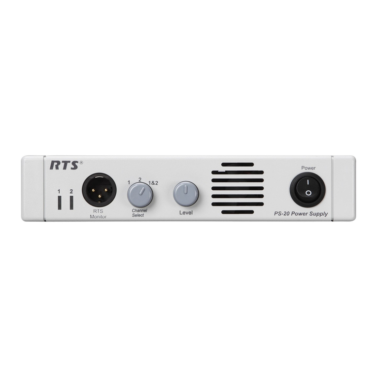
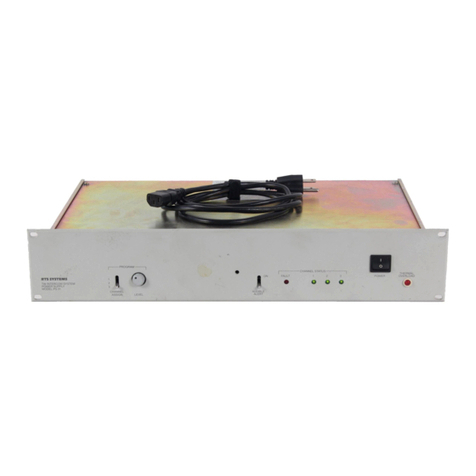
RTS PS8 User manual

R T S S Y S T E M S
PROrCSSlONAL INlERCOMMUNlCATlONS
PHOrESSlONAL AUOlO PRODUCTS
1100 WEST chestnut street
BuRBAnk. California 9tb06
telex I948b&
TECHNICAL MANUAL
8/^—^>700
P'>'rty
/-fCo'23^^-^107
TW Intercom System
MODEL PSa
Power Supply

al ULZQS__|
gg^ 'oilvwBHDg
sNaxsAssiu
lAL' :OKSn jVn
tMi'ro
HI—
»o*p ooiciti *3^
I——4—vw*—
A^«Mf6r« SV?
OOO*^'* *-
TC««9NI VI
« b 3 ^ I J m '
Arfvxo«/i f"**
A ♦8'
oV«i
«OT»
J ■iitri J «t6rtni J tdJ.
O O I > Q H J L h O O O K ?
i i b s c M « s i v o o f i : I B S
to^tfvt,
yo9bH
c»/2eX
OO'p-
OC/ttJ. KXTVro^
ioT»
nvwBoM
MT'O'I
TIU
. o
0»»TCNI
>OVt AO! J
I
»OOVHI
< V r v o l
qoooom 6TM S7I3 '3
oe& (osnj awAja ^
xtwri t wa m-^7 qaS; Y
3 S O O O O O
O O O O O
S S O O O O
O O O O O O
o o o o
o o a o

TECHNICAL MANUAL
T M 2 8 0 9
MODEL PS8 POWER SUPPLY
RTS SY S TEMS , I NCOR P ORATED
BURBANK, CALIFORNIA
SECOND EDITION
JULY, 1986
Page 1

\
TECHNICAL MANOAL MODEL PS8 POWER SUPPLY
PROPRIETARY NOTICE
The information and design disclosed herein were originated by and
are the property of RTS Systems, Inc. RTS Syste ms, Inc. reserves
all patent, proprietary design, manufacturing, reproduction, use
a n d s a l e s r i g h t s t h e r e t o , a n d t o a n y a r t i c l e d i s c l o s e d t h e r e i n ,
e x c e p t t o t h e e x t e n t r i g h t s a r e e x p r e s s l y g r a n t e d t o o t h e r s .
COPYRIGHT NOTICE
Co pyright 1986 by RTS Systems, I nc .. Reproduction in whole or i n
p a r t w i t h o u t p r i o r w r i t t e n p e r m i s s i o n f r o m RT S S y s t e m s , I n c . i s
prohibited.
TECHNICAL MANUAL
T M 2 8 0 9
MODEL PS8
POWER SUPPLY
First Edition September, 1981
Second Edition July, 1986
This manual is published by the engineering department of RTS
S y s t e m s , I n c . , w h i c h i s r e s p o n s i b l e f o r i t s c o n t e n t s .
Written by: Dan Register
Edited by: Kent Power
Address all communication regarding this publication to:
Director of Engineering
R T S S y s t e m s , I n c .
1100 West Chestnut Street
Burbank, CA 91506
Page 2

TBCBNICAL MANUAL MODEL PS8 POWER SUPPLY
T A t t L E O F C O N T E N T S
T A B L E O F C O N T E N T S 3
WARRANTY
UNPACKING INFORMATION 6
SHIPPING INFORMATION
SECTION 1: INTRODUCTION AND SPECIFICATIONS
1.1 INTRODUCTION 8
1.2 POWERING ; 8
1 . 3 . D U A L A U D I O I M P E D A N C E 9
1 . 4 C O N N E C T I O N S 9
1 . 5 P A C K A G E 9
1 . 6 S P E C I F I C A T I O N S 1 0
SECTION 2: INSTALLATION
2.1 MECHANICAL INSTALLATION 12
2 . 2 O U T P U T S 1 2
2.3 POWER AND INPUT POWER SELECTION 13
2.3.1 CONVERSION SWITCH 13
2 . 3 . 2 E X T E R N A L F U S E 1 3
2 . 3 . 3 I N T E R N A L F U S E 1 3
2.3.4 POWER INDICATOR 13
SECTION 3: OPERATING INSTRUCTIONS
3 . 1 P A N E L D E S C R I P T I O N S 1 5
3 . 2 T A N D E M O P E R A T I O N 1 9
SECTION 4: THEORY OF OPERATION
GENERAL OVERVIEW
SECTION 5: MAINTENANCE
5.0 INTRODUCTION 22
5.1 WARRANTY INFORMATION 22
5 . 2 G E N E R A L M A I N T E N A N C E 2 2
5 . 2 . 1 S A F E T Y C O N S I D E R A T I O N S 2 2
Page 3

TECHNICAL MANUAL MODEL PS8 POWER SUPPLY
TAB LE O F CONTE N TS ( CONTI N U ED)
5.2.2 ... 23
5.3 ... 24
5.3.1 F U S E R E P L A C E M E N T ... 24
5.4 ... 24
5.5 ... 26
5.6 ...28
SECTION 6: L I S T S O F R E P L A C E A B L E P A R T S
6.1 INTRODUCTION . . . . 2 9
6.2 . . . . 2 9
6.2.1 . . . . 2 9
6.3 . . . . 2 9
6.4 . . . . 3 0
6.5 PS8 REAR PANEL ASSEMBLY . . . . 3 0
6.6 PS8 CIRCUIT BOARD ASSEMBLY . . . . 3 0
SECTION 7: . . . . 3 3
. . . . 3 3
. . . . 3 4
. . . . 3 5
I N D E X O F F I G U R E S
2-1 OU TLI NE DR AW I NG , M OU N TIN G OPT ION S ....12
2-2 OUTLINE DRAWING, MODEL PS8 POWER SUPPLY . . . . 1 4
3-1 . . . . 1 6
3-2 . . . . 1 6
3-3 MODEL PS8 CAPACITY, LOCAL . . . . 1 7
3-4 ....18
3-5 ....19
4-1 .... 21
5-1 . . . . 2 5
Page 4

TBCHNICAL MANUAL MODEL PS8 POWER SUPPLY
R T S S Y S T E M S * L I M I T E D W A R R A N T Y
Th e products o£ RTS System s/ l nc «r a C alifornia corporation ^ ar e
w a r r a n t e d t o b e f r e e f r o m d e f e c t s i n m a t e r i a l s a n d w o r k m a n s h i p f o r a
period of one year from the date of sale*
RTS Systems' sole obligation during the warranty period is to
pro vide r with out c h arg ey par ts an d l abo r nece ssa r y to ra nedy
covered defects appearing in products returned prepaid to RTS
Systems, 1100 W. Chestnut Street, Burbank, California, 91506,
U.S.A.• This warranty does not cover any defect, malfunction or
failu re ca used be yond th e con trol of RTS Sys tem s, incl uding
unreasonable or negligent operation, abuse, accident, failure to
f o l l o w i n s t r u c t i o n s i n t h i s M a n u a l , d e f e c t i v e o r i m p r o p e r
associated equipment, attempts at modification and repair not
authorized by RTS Systems, and shipping damage. Products with
t h e i r s e r i a l n u m b e r s r e m o v e d o r e f f a c e d a r e n o t c o v e r e d b y t h i s
warranty.
To o b t a i n w a r r a n t y s e r v i c e , f o l l o w t h e p r o c e d u r e s e n t i t l e d
"PROCEDURE FOR RETURNS" and "&HIPPING TO MANUFACTURER FOR REPAIR OR
ADJUSTMENT** listed below.
Thi s w arr a nty i s t he so l e and e x clu sive e xpre ss war rant y give n with
r e s p e c t t o R T S S y s t e m s ' p r o d u c t s . I t i s t h e r e s p o n s i b i l i t y o f t h e
u s e r t o d e t e r m i n e b e f o r e p u r c h a s e t h a t t h i s p r o d u c t i s s u i t a b l e f o r
t h e u s e r ' s i n t e n d e d p u r p o s e .
ANY AN D ALL IMPL IED WARRANTI ES, IN CLUDING THE IMPL IED WARRANTY
O F M E R C H A N T A B I L I T Y A R E L I M I T E D T O T H E D U R A T I O N O F T H I S E X P R E S S
LIMITED WARRANTY•
N S X T H B R R T S S Y S T E M S N O R T H E D E A L E R W H O S E L L S RT S S Y S T E M S '
PRODUCTS IS LIABLE FOR INCIDENTAL OR CONSEQUENTIAL DAMAGES OF
ANY KIND.
Page 5

\
\
TECHNICAL MANUAL MODEL PS8 POWER SUPPLY
UNPACKING INFORMATION AND IHSPBCTION
Immediately upon receipt of your Model PS8, take the time to
carefully e xamine the pa ckage for any discrepancies or dama ge.
Sh ould you di sc over any, n otify the fre ight compan y an d your dealer
at once.
Your shipping container should contain the following components:
MODEL PS8 POWER SUPPLY
L a r g e R a c k E a r
S m a l l R a c k E a r
Rubber Feet
O w n e r ' s M a n u a l
P l a s t i c B a g
9010-27 32-00
9110-2044-02
9110-1609-02
4501-5027-00
T M 2 8 0 9
Your shipping container should be saved as it is specially designed
for transporting this equipment in good condition.
Page 6
I

TECHNICAL NANOAL MODEL PS8 POWER SUPPLY
RETURN SHIPPING INSTRUCTIONS
PROCEDURE FOR RETURNS
If repair is necessaryr contact the dealer where this unit was
purchased•
If repair through the dealer is notpossible^ contact the RTS
Systems Customer Service Department by telephoner as directed
below f -to ob«li i a Return Au thor i^ation Nuiaber.
DO NOT RETURN ANY EQUIPMENT DIRECTLY TO THE FACTORY
WITHGOT FIRST OBTAINING A RETURN AUTHORIZATION NUMBER.
Be prepared to provide your company's name* address^ phone number# a
person to contact regarding the repair# the type and quantity of
equipment# a description of the defect# and the serial number (s) *
Questions regarding returns for repair should be directed to:
C u s t o m e r S e r v i c e D e p a r t m e n t
RTS Systems# Inc.
1100 W. Chestnut St.
Burbank# CALIFORNIA 91506# U.S.A.
Telephone: (818) 840-7311
TELEX: 194855
TWX: 910-498-4987
T E L E F A X : ( 8 1 8 ) 8 4 2 - 4 9 2 1
SHIPPING TO MANUFACTURER FOR REPAIR OR ADJUSTMENT
All shipments of RTS Systems# Inc. equipment should be made via
U n i t e d P a r c e l S e r v i c e o r t h e b e s t a v a i l a b l e s h i p p e r # p r e p a i d . T h e
equipment should be shipped in the original packing carton; if that
is not available# use any suitable container that is rigid and of
adequate size. If a substitute container is used# the equipment
should be wrapped in paper and surrounded with at least four inches
o f e x c e l s i o r o r s i m i l a r s h o c k - a b s o r b i n g m a t e r i a l . A l l s h i p m e n t s
s h o u l d b e d i r e c t e d t o t h e a t t e n t i o n o f t h e C u s t o m e r S e r v i c e
Department and must include the Return Authorization Number.
Upon completion of repairs equipment will be returned via United
P a r c e l S e r v i c e o r s p e c i fi e d s h i p p e r # c o l l e c t .
Page 7

TECHNICAL MANUAL MODEL PS8 POWER SUPPLY
SECTION 1: INTRODUCTION AMD SPECIFICATIONS
1.1 INTRODUCTION
I n t h e T W I n t e r c o m S y s t e m , t h e p o w e r s u p p l y i s c o n s i d e r e d t h e h e a r t
o£ the system. The Model PS8 Power Supply is designed to function
i n a p p l i c a t i o n s e m p l o y i n g s m a l l - s i z e T W I n t e r c o m S y s t e m s . T h e u n i t
is completely self-contained and features two-channel operation;
one "wet" channel with 32 volts DC and one "dry" channel without
voltage potential* Each channel provides an audio termination
impedance of 200 ohms.
T h e M o d e l P S 8 i s m e c h a n i c a l l y a n d e l e c t r i c a l l y b u i l t t o i n d u s t r i a l
quality standards, insuring long-term usage and performance.
O u t p u t s a r e p r o t e c t e d a g a i n s t s h o r t c i r c u i t c o n d i t i o n s w i t h
recovery being automatic and instantaneous. Protection circuitry
pr ev en ts damage to the power supply from accidental connection to
1 2 0 v o l t A C p o w e r l i n e s .
1.2 POUERING
A sin gl e PS8 Power Supply po we rs: twelve user sta ti on s without call
l i g h t s , s e v e n s p e a k e r s t a t i o n s w i t h o u t c a l l l i g h t s , s e v e n u s e r
s t a t i o n s w i t h c a l l l i g h t s , o r fi v e s p e a k e r s t a t i o n s w i t h c a l l ^
l i g h t s . O f c o u r s e , a c o m b i n a t i o n o f s t a t i o n s m a y b e u s e d . w i t h
respect t o maximum c urrent ca pabilit y. See F ig ure 3-3 a nd F igure 3 -4
f o r M o d e l P S 8 p o w e r i n g c a p a b i l i t y .
I f s t i l l m o r e u s e r s t a t i o n s a r e n e e d e d , t w o P S 8 P o w e r S u p p l i e s c a n
b e a u d i o c o u p l e d t o g e t h e r t o d o u b l e t h e p o w e r i n g c a p a b i l i t y ; a 1 / 4 -
i n c h 3 - c i r c u i t p h o n e j a c k i s a v a i l c U D l e f o r t h i s p u r p o s e . T h i s
connector can also be used as a one-way output port when monitoring
o r r e c o r d i n g t h e i n t e r c o m a u d i o s i g n a l s .
Page 8

TECHNICAL MAHUAL MODEL PS8 POWER SUPPLY
1.3 DUAL AUDIO IMPEDANCE
Wben two PS8*s are combined, an impedance select switch on each PS8
m a i n t a i n s , i n e ff e c t , t h e 2 0 0 o h m l i n e t e r m i n a t i o n w h i l e t h e p a i r o f
units provides the equivalent current of what would be
a p p r o x i m a t e l y a P S 2 0 . I n t h e n o r m a l p o s i t i o n , t h e s w i t c h s e t s t h e
i m p e d a n c e t o 2 0 0 o h m s w h i l e i n t h e d u a l p o s i t i o n , a 4 0 0 o h m
impedance is established. The parallel combination of 400 ohms
between the two power supplies now becomes 200 ohms: the noninal
line impedance for the TW Intercom System.
1.4 CONNECTIONS
T h e r e a r e t w o X L R - t y p e 3 - p i n m a l e c o n n e c t o r s m o u n t e d o n t h e r e a r
panel for output interconnection to the user stations. (The PS8
i t s e l f d o e s n o t h a v e p r o g r a m i n s e r t i o n c a p a b i l i t y ) .
1.5 PACKAGE
T h e P S 8 i s h o u s e d i n a m e t a l e n c l o s u r e m e a s u r i n g 1 . 7 5 i n c h e s h i g h b y
8.38 inches wide by 7.5 inches deep. The unit is completely
e n c l o s e d a n d m a y b e u s e d f r e e s t a n d i n g , o r r a c k m o u n t e d . A l l
e l e c t r i c a l c o m p o n e n t s a r e a s s e m b l e d o n a s i n g l e c i r c u i t b o a r d
a l l o w i n g e a s y a d j u s t m e n t . o r s e r v i c i n g ; i m m e d i a t e a c c e s s i s
accomplished by removing four screws and sliding the top and bottom
c o v e r s b a c k a l o n g t h e i r r e s p e c t i v e c h a n n e l s .
Page 9

TECHNICAL MANUAL MODEL PS8 POWER SUPPLY
1 • 6 SPECIFICATIONS
OUTPUTS: One powered channel, CHI
( a u d i o + D C + 2 0 0 o h m a u d i o t e r m i n a t i o n )
One passive channel, CH2
(audio + 200 ohm audio termination)
OUTPUT VOLTAGE:
Nominal open circuit
Full load
+32 volts, +0.5 V,-1.5 V
+26 volts
OUTPUT IMPEDANCE:
OUTPUT CURRENT
200/400 ohms switchable
On powered channel: 200 ohms is
maintained from
1 7 t o 3 2 v o l t s o u t p u t
@ 2 6 v o l t s
@ 3 2 v o l t s
0.4 amps
0.5 amps
I N T E R C O M A U D I O :
NOMINAL LEVEL:
M I N I M U M H E A D R O O M :
2 . 0 v o l t s p - p
6 d B m i n i m u m
TERMINATION:
Both channels
2 0 0 o r 4 0 0 o h m s ± . 1 0 %
FREQUENCY RESPONSE:
-3 dB, no load
7 5 H e r t z t o 2 0 K H z
S I G N A L T O N O I S E R A T I O :
R e f . 2 . 0 V p p
55 dB
Page 10

TECHNICAL MANUAL MODEL PS8 POWER SUPPLY
TEMPERATURE
0® to +50®C
-40® to +70°C
POWER REQUISEMBHT: 24 volt-amps
(120/240 VACf 50-60 Hz)
DIMEHSIONS:
Height:
Width:
Depth:
Weight:
Finish:
1 . 7 5 i n c h e s ( 4 3 . 6 2 m m )
8 , 3 7 5 i n c h e s ( 2 1 2 . 7 3 m m )
7 . 5 0 i n c h e s ( 1 9 0 . 5 0 m m )
5 pounds (2.25 kilograms)
Light gray enamel paint
SPECIFICATION NOTES:
0 d B u s 0 . 7 7 5 r . m . s .
N O T I C E : A l l p r o d u c t i o n i n f o r m a t i o n a n d s p e c i fi c a t i o n s a r e s u b j e c t
to change without notice*
Page 11

TECHNICAL MANOAL MODEL PS8 POWER SUPPLY
SECTION 2: INSTALLATION
2.1 MSCBAHICAL INSTALLATION (See Figure 2-1, Outline Drawing
Mounting Options, Figure 2-2, Outline Drawing, and Figure 7-3,
Installation Diagraun*)
The Model PS8 can be installed in 3 ways. A single unit can be
mounted in a half raclc space using the rack ears provided; or.two
P S 8 ' s c a n b e m o u n t e d s i d e b y s i d e u s i n g t h e h o l e s p r o v i d e d i n t h e
s i d e r a i l a l o n g w i t h t h e s h o r t r a c k e a r s ; o r t h e u n i t s c a n b e f r e e
s t a n d i n g u s i n g t h e s t i c k - o n r u b b e r f e e t . T h e r a c k e a r s c o n f o r m t o
s t c u i d a r d E I A r a c k s i z e s a n d e a c h e a r c a n b e u s e d o n e i t h e r s i d e o f
the unit.
To install the Model PS8 first select the configuration to use in
y o u r a p p l i c a t i o n . I f m o u n t i n g f r e e s t a n d i n g p l a c e t h e s t i c k - o n
r u b b e r f e e t o n t h e b o t t o m o f t h e u n i t i n t h e f o u r c o r n e r s .
If rack mounting care fu lly remove the cove r of t he unit by removing
t h e s c r e w s a n d s l i d i n g o f f t h e c o v e r . T h e r e a r e 2 s c r e w s o n e a c h
s i d e r a i l o f t h e u n i t . R e m o v e t h e m . N e x t p l a c e t h e r a c k e a r s o n t h e
s i d e s o f t h e u n i t a n d r e - a t t a c h t h e s c r e w s t o t h e s i d e r a i l s . T h e
nut and w asher go on the inside of the unit. Be careful not to jar
o r s t r i k e a n y o f t h e e l e c t r o n i c c o m p o n e n t s i n s i d e o f t h e u n i t . I f
u s i n g t w o u n i t s s i d e - b y - s i d e f a s t e n t h e t w o u n i t s t o g e t h e r t h r o u g h
t h e 2 h o l e s o n t h e c o m m o n s i d e o f e a c h u n i t ; t h e n a t t a c h t h e s h o r t
r a c k e a r s t o t h e o p p o s i t e s i d e s . N o w r e - a t t a c h t h e t o p c o v e r a n d
fasten the unit to the rack.
2*2 OUTP U T S L o c ated on th e b a c k p anel are th e o u t p uts. T he PS8
is designed to accept standard XLR 3-pin fem«^.e connectors.
S TA N D A L O N E S I N G L E R A C K M O U N T TA N O E M R A C K M O U N T
Figure 2-1
Outline Drawing, Mounting Options
Page 12

I
TECHNICAL MANUAL MODEL PS8 POWER SUPPLY
2.3 POWER and INPUT POWER SELECTION Located on the back
panelr lower left# is the power cord. It is standard 18 gauge# 3
wire cord# 6 feet long with CEE color code* It has a standard North
American 3 prong plug.
2.3.1 115/230 CONVERSION S1IITCH Located internally, behind
the external fuse and mounted on the P.O. board is the 115/230
c o n v e r s i o n s w i t c h . To g a i n a c c e s s t o t h i s s w i t c h , t h e t o p ' c o v e r
must be removed. This is accomplished by removing the two 4-40
phill ips h ead s crews in the t op co ver and s lid ing t he cove r ope n.
WARNING: SEE SECTION 5.3 CONCERNING POTENTIAL SHOCK HAZARD1
2 . 3 . 2 E X T E R N A L F U S E L o c a t e d o n t h e b a c k p a n e l , u p p e r l e f t , i s
t h e e x t e r n a l f u s e . T h e f u s e h o l d e r i s a s t a n d a r d i n t e r n a t i o n a l t y p e
which accepts a standard 1/4 inch by 1 1/4 inch AGO or 3AG slo-blo
f u s e . R e f e r t o t h e f u s e t a b l e f o r t h e a p p r o p r i a t e f u s e s i z e .
2 * 3 * 3 I N T E R N A L F U S E M o u n t e d o n t h e P . C . B o a r d , b e h i n d t h e
e x t e r n a l f u s e i s t h e i n t e r n a l f u s e . To g a i n a c c e s s , r e m o v e t h e t o p
cover by unscrewing the screws and sliding the cover open. Refer to
t h e f u s e t a b l e f o r t h e a p p r o p r i a t e f u s e s i z e .
The in t e rnal f u s e is use d a s a s econd a ry safe t y d evic e . I t is one
fuse larger than' the externeJ. fuse. If the external fuse is blown
a n d a l a r g e r f u s e i s p u t i n t o i t s p l a c e , t h e i n t e r n a l f u s e w i l l b l o w
b e f o r e t h e u n i t i s d e s t r o y e d . I f t h e f u s e s k e e p o n b l o w i n g , t h e
unit needs servicing.
F U S E T A B L E
1/2 amp, slo-blo
1/4 amp, slo-blo
1 amp, slo-blo
1/2 amp, slo-blo
Wheii reinstalling the top cover, the two screws must be installed
c a r e f u l l y t o i n s u r e a g o o d g r o u n d c o n n e c t i o n b e t w e e n t h e c o v e r a n d
the chassis.
2.3.4 POWER INDICATOR Located on the front panel, bottom
r i g h t , i s t h e p o w e r - o n i n d i c a t o r. I t i s a g r e e n l i g h t e m i t t i n g
d i o d e ( L E D ) .
Page 13
/
/

TBCBNICAL MANUAL MODEL PS8 POWER SUPPLY
(53.02)
—'5.2 -
(ZOQ.B)
mi&HT: 4.0LBS Ct.SiC^)
Figure 2-2
Outline Drawing, Model PS8 Power Supply
Page 14

I
TECHNICAL MANUAL MODEL PS8 PC3WER SUPPLY
SECTION 3: OPERATING INSTRUCTIONS
3.0 INTRODUCTION
T h e o p e r a t i o n s e c t i o n i s d i v i d e d i n t o 2 p a r t s : f r o n t a n d b a c k p a n e l
description and tandem operation.
3 . 1 PA N E L D E S C R I P T I O N ( S e e F i g u r e s 3 ^ 1 a n d 3 - 2 )
R £ F N A M E F U N C T I O N
1 P O W E R L E D p o w e r o n i n d i c a t o r .
2 P O W E R C O R D G o e s t o a c l i n e , 1 2 0 o r 2 4 0 v o l t s
switch selected inside.
3 F U S E
^ 4 AUDIO COUPLING
5 OUTPUTS
6 N O R M D U A L S W I T C H
Fuse holder. Use a 1/2 amp slo-blo
f u s e f o r 1 2 0 v o l t o p e i r a t i o n ; u s e a
1/4 a mp slo-blo f use f or 24 0 vol t
o p e r a t i o n . A m e t r i c f u s e c a r r i e r i s
a v a i l a b l e t o fi t t h i s s a m e h o l d e r
A 1 / 4 i n c h s t e r e o p h o n e j a c k .
Provides an unbuffered audio output.
May be used to connect two PS-8's
together.
3-pin male XLR-type connectors.
T h e s e f e e d t h e R T S " T W * * u s e r
stations.
A t o g g l e s w i t c h . S e l e c t s 2 0 0 o r 4 0 0
ohm impedance. The NORMal positon
is used when the power supply is used
s i n g l y. T h e D U A L p o s i t i o n i s u s e d
w h e n t w o P S - 8 ' s a r e c o n n e c t e d
together through the audio coupling
jack.
Page 15

T B C B N I C A L M A N U A L M O D E L P S S P O W E R S U P P LY
S^&ns
MODEL PSB
powensuppiy
Figure 3-1
PS-8 FRONT PANEL
awiT»M-i0«WMBiiiW0» II rm
asA SB
/)) VV>^v }) o-asA sa
aaovAC cauPUNO
C M 1 / C H a
O O
^ O >
O O
V O >
PMPOwvisuMvf KtssvsTtus.we.auNa«M(.c* usa
Figure 3-2
PS-8 REAR PANEL
Page 16

TBCHNICAL MANUAL MqDEL PS8 POWER SUPPLY
S^S^Bgggsaaai
I—if—
laaaaraaaaaaaaaaaaiBa
SPEAKER STATIONS
Figure 3-3
PS8 CAPACITY, LOCAL
Page 17

tbcbnical mamoal model psa powsb sopflx
5^a—BWBSggsaMBai
S.
=s== PS-8 CAPACITY
To 1/2 mile with #22 wire
2 5
S 4
nOaaa>"|
AvBanl
:■■■ ——li—■■■ MkwpitW——I W—»B—■■■■■■■ —I
SraSaauMnMaMSSSSSSMaaSuL^KSSMSaHMiBamaBiSMaaBawaal
miS^SaMUHaSiiMaaSBSMBMnSVliiamniBBaaaaBMiaaaiSiintaav-nal
M B M i a i n S S S n S r a a S S a S S a a a S i S S ^ W i a a a a a a a a a a a m a M a i a m a a a ^ a a
3 4 5
SPEAKER STATIONS
Figure 3-4
PS8 CAPACITY 9 LONG DISTANCE
Page 18
Table of contents
Other RTS Power Supply manuals
Popular Power Supply manuals by other brands

Philips
Philips PDS-150e Product guide

Glensound
Glensound Signature Series user guide

Huawei
Huawei SmartLi 3.0 quick start guide

Beckhoff
Beckhoff PS1061-2405-0000 installation manual

Trane Technologies
Trane Technologies PM014 24 Installation, operation and maintenance

Wisenet
Wisenet SBP-C14PS1 Installation and operation manual