Ruff Cycles Lil'Buddy Installation instructions

1
ORIGINAL OPERATING MANUAL

2 3
Manufacturer:
RUFF CYCLES GmbH
Im Gewerbepark D36
93059 Regensburg
Germany
support@ru-cycles.com
www.ru-cycles.com
V1.1, September 2020
Layout, photographs and text: RUFF CYCLES GmbH, Regensburg, Germany
Texts passages were provided with courtesy of HNF GmbH
The mentioned brand names are subject to copyrights and are the property of their legitimate
owners even without special indication. Any reprint or copy, even only in extracts, is only permitted
with our express written consent. Subject to misprints, errors and technical alterations. Please
note that the illustrated product may be dierent from the delivery condition of the product.

4 5
1.
Your Vehicle 7
1.1. Intended use 7
1.2. Vehicle overview 9
1.3. Delivery scope 10
1.4. Assembly of accessories 10
2. Commissioning 10
2.1. Handlebar alignment 10
2.2. Pedal assembly 11
2.3. Removal/Installation of the battery 12
2.4. Switching ON/OFF the drive 12
2.5. Adjusting support level 12
2.6. Switching ON/OFF the lamp 13
2.7. Initial engagement of brake discs 13
3. Before each ride 14
3.1. Check tires 14
3.2. Checking the brake system 14
3.3. Checking the chain 15
3.4. Battery: Checking the fixation and charging status 15
3.5. Checking the fork 15
3.6. Checking the screw connections 16
3.7. Checking the lights 16
4. Operating 17
4.1. Shimano derailleur gear 17
4.2. Drive units 17
4.2.1. Chain Drive Units 17
4.3. Brake system 18
4.4. Side stand 18
5. Ergonomic setting 19
5.1. Brake lever 19
5.1.1. Adjusting brake lever position 19
5.1.2. Brake grip angle 20
5.1.3. Adjusting brake lever distance 20
6. Maintenance 20
6.1. Wear parts list 21
6.2. Recommended maintenance intervals 22
CONTENTS
6.3. After an accident 22
6.4. Battery 23
6.5. Tires 23
6.6. Changing tires/tubes 24
6.6.1. Dismounting the front wheel 24
6.6.2. Dismounting the rear wheel 25
6.6.3. Changing tires/tubes 26
6.6.4. Front wheel assembly 26
6.6.5. Rear wheel assembly 27
6.7. Adjusting the Chain derailleur 27
6.8. Brakes 27
6.8.1. Wear of brake pads and discs 27
6.8.2. Checking the brake pads 28
6.9. Setting the headlight range 28
7. Cleaning and maintenance 29
8. Transport on/by car 30
9. Technical data 30
9.1. Component list 30
9.2. Weights 31
9.3. Torque of screws 31
10. Liability for Material Defects 33
11. EC declaration of conformity 34
12. Disposal 35

6 7
Index and symbols in this User Manual
This User Manual contains important information for the enhanced safety and
prolonged service life of the Pedelec for an each time greater fun with your
Lil’Buddy.
Any neglect of the contents of this User Manual may lead to damages to the
vehicle as well as injuries.
The following symbols are used in the User Manual:
Warning!
This symbol indicates a possible danger.
Please observe the safety instructions!
Information
Here, you will find useful information on the maintenance of the
product.
Important information!
The User Manual of your Lil’Buddy is constantly checked and updat-
ed. This instruction corresponds to our level of knowledge at the time
of publication. We recommend you to visit our website
www.ru-cycles.com/manuals, for any modifications. Here you can
also download the updated manual in PDF format.
1. YOUR VEHICLE
We congratulate you to the purchase of the Lil’Buddy with BOSCH driving
technology.
You have decided for a state-of-the-art means of transport, which allows you
brand-new mobile options. We have attached the greatest importance1 to the
technical quality of the single components of your Pedelec, ensuring that you
will enjoy your Lil’Buddy for many years.
The Lil’Buddy is a bicycle with electrical power assistance for the driver. This
aid is adjusted via a controller that evaluates the data through three sensors
(speed, step rate and torque), regulating the motor according to the selected
support level. When reaching a speed of 15.53 miles/h (25 km/h), the electri-
cal motor switches o. But driving at a speed of 15.53 miles/h (25 km/h) by
oneself is also possible.
In Germany, the Pedelec is lawfully equivalent to the bicycle2. No permit or
license plate are required. The driver does not need a driver license. We do
recommend that you wear an appropriate helmet and goggles for your own
safety.
1.1. INTENDED USE
Your Lil’Buddy is intended for the transport of one person on asphalt roads
and rideable forest and land routes. The additional allowable load
(Driver + Accessory + Baggage) amounts to 150kg.
The Lil’Buddy is not intended for:
»Racing/Competition
»Cleaning with a water jet
»Transport in the rain by a car without covering the motor and
dismantling the battery and display
»Charging the Pedelec outdoors in a wet environment
1 Pedal Electric Cycle
2 § 1 Par.3 StVG (Street trac act)
YOUR VEHICLE

8 9
The required active and passive illumination devices have been installed
according to the safety regulations applicable in Germany (StVZO). The tech-
nical design safety must be regularly checked and eventually be repaired by a
specialist.
1.2. VEHICLE OVERVIEW
The serial number is found on the plate on the lower tube directly below the
motor. The type plate is located on top of the motor mounting holder.
Please note down the serial number of the Lil’Buddy
here:___________________________________________
Intended use is also limited by:
»The safety instructions in this User Manual
»The „Technical data“ chapter in this User Manual
»The national regulations for street transport (StVO)
»The national regulations for the street transport permit ordinance (StVZO)
The following user groups should not use the Pedelec:
»Persons with a limited physical, sensory or mental capacity.
»Persons who due to their body size, cannot safely drive the bicycle.
Any changes to your Lil’Buddy increasing the motor output or max-
imum support speed, will endanger your driving safety and con-
vert the vehicle from a Pedelec into a small motorcycle. You will be
exposed to sanctions in accordance with trac, licence and safety
regulation with penal consequences!
Rotating parts such as wheels, chain ring, sprocket, pedal crank or
pedals may draw into clothing, carried objects and even body parts,
e.g. your shawl or a bag attached to the handlebar may get caught
into the spokes during driving. When you slip your feet from the
pedals, they can get caught into the spokes. This may lead to severe
accidents!
-> Always wear tight-fitting clothes.
-> Wear shoes with non-slip, flat soles.
-> Do not attach objects onto the handlebar, as they may swing into
the front wheel.
A Pedelec always accelerates faster than a bicycle. Be always aware
that other trac participants cannot always predict your acceleration
performance.
-> Exercise your new Lil’Buddy first at a quiet location, before riding
in the busy streets.
-> Exercise the brakes. Please see also chapter 4.3. „Brake system“.
YOUR VEHICLE
21 543 6
7
8
YOUR VEHICLE
1 Shimano BL-MT201 6 Engine
2 Shimano Altus 7-Gear 7 Battery
3 Chain tensioner 8 Fork
4 Kickstand 9 Type Plate
5 Chain 10 Control Unit
9
10
10

10 11
1.3. DELIVERY SCOPE
»Bosch charging device
»2 keys for securing the battery to the Pedelec
»2 transport fixations for the Shimano BL-MT201 brakes
»Bosch hazardous material package for battery shipment (please store and
when appropriate, use this for the disposal or return of the defect battery)
»Delivery package (please store if you consider to cancel the purchase within
two weeks)
User manuals of dierent component manufacturers
1.4. ASSEMBLY OF ACCESSORIES
When installing accessories like child seat or trailer, please check the com-
patibility with the Pedelec through the accessory manufacturer or a bicycle
dealer.
2. COMMISSIONING
This chapter explains how to prepare your Lil’Buddy for the ride.
Inflate the tires first. The air pressure volume is described in chapter 3.1.
Your Lil’Buddy is supplied as a part assembly and as a full assembly.
In the latter case, you can skip items 2.1. and 2.2.
If it is not a standard delivery, please read the following items for
„handlebar alignment“ and „Pedal assembly“.
2.1. HANDLE BAR ALIGNMENT
The stem is a significant safety component. When tightening the bolts,
ensure that you use the torque as defined in the torque table under
9.3. Otherwise, there is a hazard of accident!
»Lift the vehicle by the front frame, so that it no longer touches the ground.
Turn the fork leftwards and rightwards. The front wheel must follow the
movement. This simulated steering operation should not be dicult.
»If the steering is not rotated easily, the ahead bolt is tightened too fast (1).
Loosen it by releasing the 2 screws (2) of the
stem. Now you can adjust the compression
of the steering bearing with the ahead bolt.
Retighten the stem screw with a torque of
6-7 Nm.
»Finally, clamp the handlebar in the middle
by tightening the bolts (3) at the cross on the
stem. Ensure a uniform front and rear gap
between stem and cover.
2.2. PEDAL ASSEMBLY
The right pedal has a right thread, the left pedal has a left thread
on the pedal axis. The right pedal is mounted clockwise and the left
pedal is mounted counter-clockwise. The pedals are marked with R
and L.
Pedals are important safety components. Make sure that you tighten
the pedal axis firmly, according to the manual. Otherwise, there is a
hazard of accident!
»Apply a thin layer of grease onto the thread of the pedal axis and the crank.
Next, screw the pedal by hand loosely into place. Consider the correct assem-
bly angles in order to avoid tilting.
»Place the crank in a horizontal position, the
right pedal oriented towards the front wheel.
»Tighten the pedal with an SW 15 open end
wrench at 30 - 35 Newton meter.
COMMISSIONINGYOUR VEHICLE
3
2
1

12 13
2.3. REMOVE THE BATTERY
1. Before removing the battery, ensure that the
system is disconnected. Turn the key in the
lock by 90° rotation while tilting the battery
from the upper bracket.
2. Pull the battery from the bracket.
»Installing the battery:
Install the battery with its contacts onto the
lower bracket and tilt it up to the stop into the
upper bracket, until the lock snaps in audibly.
2.4. SWITCHING THE DRIVE ON OR OFF
»you have dierent ways how you can switch
the eBike-System on and o:
»press the on/o button of your board compu-
ter when the battery is installed
»press the on/o button of the eBike battery
(see battery manual)
2.5. ADJUSTING SUPPORT LEVEL
For the adjustment of the support level, press the „+“ button on the control
unit until the required support level is shown on the display. To lower it, press
the „–“ button.
2.6. SWITCHING THE LIGHT ON OR OFF
»Make sure that the Bosch Motor is on.
»By pressing the button + for a few seconds,
front and backlight will be turned on.
»To turn the lights o, press the + button for
a long time.
Detailed information on the operation of the board computer is
found under 4.1.1. Purion board computer.
2.7. INITIAL ENGAGEMENT OF BRAKE DISCS
Your brake system is delivered with a weak break function, because the
surfaces of the brake discs and pads have not been engaged yet. With a new
Pedelec, and also when changing the brake discs and pads, you should en-
gage the brake discs as follows:
»Accelerate the Pedelec to approx. 15.53 miles/h (25 km/h)
»Brake the Pedelec by both brakes until standstill
(avoid to block the wheels!)
»Repeat this procedure as often as required in order to achieve an optimal
brake performance.
If you force too much the front wheel brake, a hazard of tipping over
exists. Your rear wheel might lift and have you fall over the handlebar.
-> Pull a little less at the left brake lever, or fully release the brake
lever, when you notice that the rear wheel is lifted.
COMMISSIONINGCOMMISSIONING

14 15
The pressure point is the lever position of the travel at which the
brake is engaged. If brakes function smoothly - there are no air bub-
bles in the hydraulic line - the pressure point is situated at the same
lever position at each braking action.
Do not touch the brake discs with your hands. The thin grease film
on your skin is transmitted to the brake discs and aects its func-
tions.
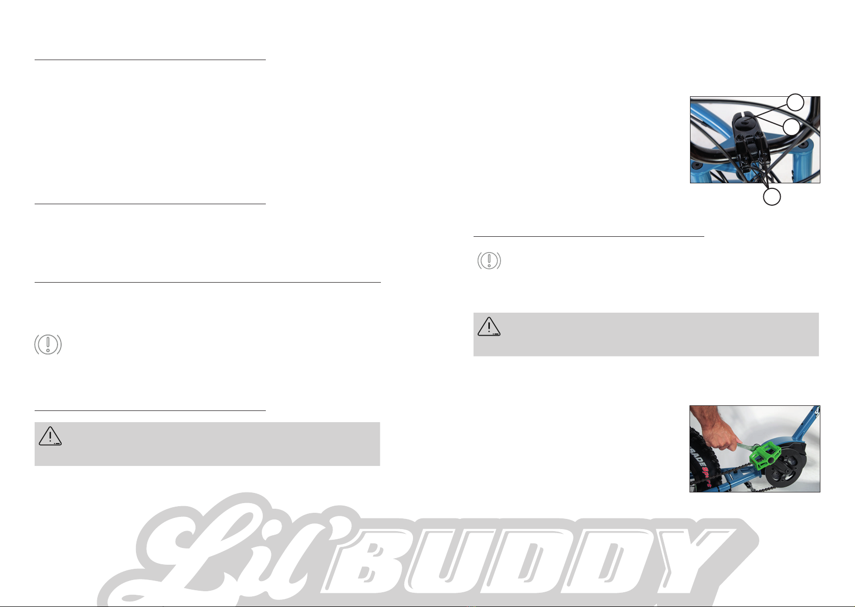
3.3. CHECKING THE CHAIN
The chain is a product subject to wear. Please check regularly the following
items:
»Are there any foreign objects (twigs) between the chain links?
-> If so: Remove them.
»Is the chain very dirty?
-> If so: Rinse it with water or a proper cleaning solution. Then use a first
class chain lubricant.
»Lubricate the chain at regular intervals, even when it is not dirty, in order to
prevent it from significant wear.
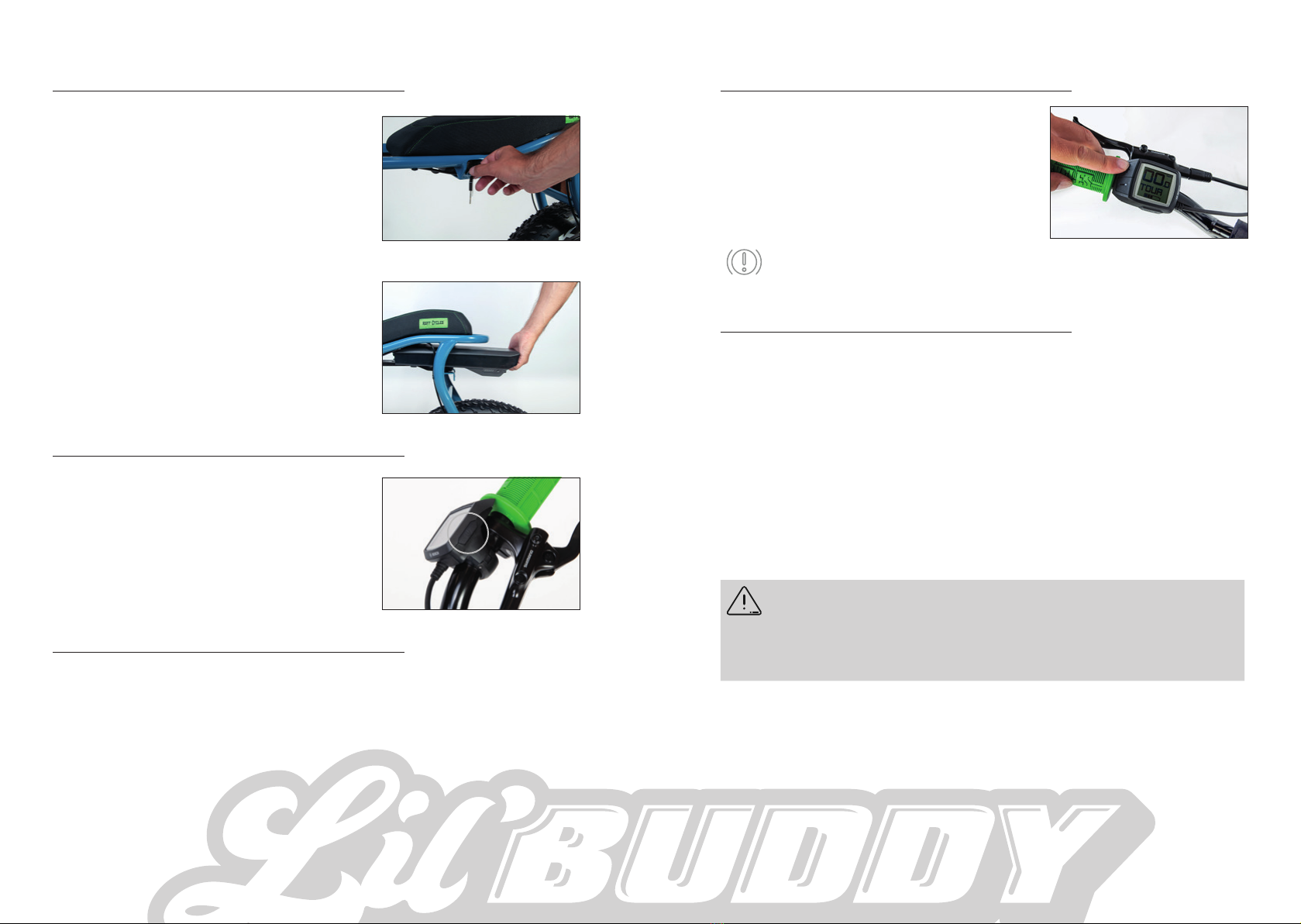
3.4. BATTERY: CHECKING THE FIXATION AND CHARGING STATUS
Check whether the battery is secured in the lock and see whether the charg-
ing status is sucient for your planned ride.
3.5. CHECKING THE FORK
Before each ride, check the fork for:
»Breakage and deformations
»Secure fixation of the protective plate
»Firm screwing connection of the fork bridge
BEFORE EACH RIDE
3. BEFORE EACH RIDE
3.1. CHECK TIRES
Tire pressure:
The allowed pressure range of the 20“ 98-406 is between 1 and 1.5 bar.
The following applies: The higher your weight, the higher the air pressure
to be used.
If you are not a light-weight person, set the pressure
of your rear tire at 1.5 bar.
We recommend to check the pressure every 2 - 4 weeks, since there
is an inevitable constant pressure loss of the inner tubes.
With a too low tire pressure, a puncturing hazard exists (snakebites).
This will result in a flat tire.
A tire that is damaged by tears or punctured by a sharp object may
loose its pressure. A hazard of accident exists!
-> Check that your tires are without tears or any foreign objects.
3.2. CHECKING THE BRAKE SYSTEM
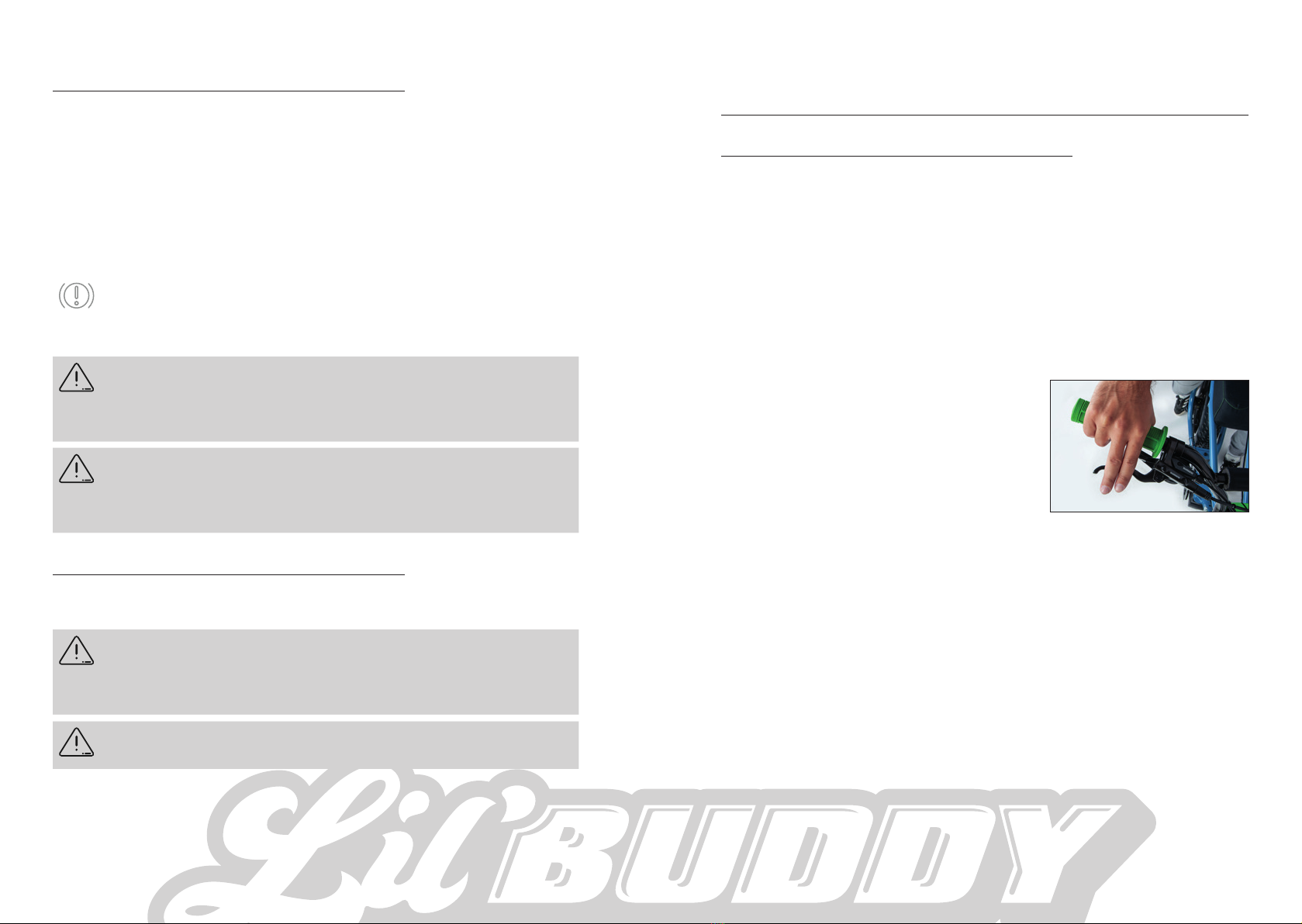
»Before each ride, check your brakes at standstill. For this purpose, pull the
brake lever towards the handlebar with two fingers for a normal braking
force. The brake lever must not touch the handlebar grip
»Move the Pedelec while pulling the front and rear brakes. A too strong a play
is not allowed. If you notice any play, identify the cause. The brake calliper or
brake disc may not be tightened firmly. Tighten according to the torques in
the torque table in chapter 9.3.
»If hydraulic brake discs are used, the pressure point must be stable at the
brake lever. If the pressure point is not reached after 2/3 travel of the lever,
pull the lever several times in a row (“pumping”). Check whether the pressure
point has stiened. If so, or when the pressure point changes during the ride,
bleed the brake system by a specialist workplace.
»The brake discs must be oil-free. Any oil on the brake discs is removed with
alcohol. Do not use a conventional brake disc cleaning solution!
BEFORE EACH RIDE

16 17
3.6. CHECKING THE SCREW CONNECTIONS
Before each ride, check the firm screw connections for
»Quick release of the front wheel
»Thru axle of the rear wheel
Also check that the following parts do not rotate:
»Seatbench
»Handlebar
»Stem
Lift the vehicle slightly up and let it fall onto the ground by the tires. Check
whether you see or hear any loose parts. Identify the cause of any loose parts
and check if their torque is correct. If required, consult a specialist dealer.
3.7. CHECKING THE LIGHTS
Before each ride, check the function of the lights. Ensure that the headlamp
is directed according to the lighting range defined by the national regula-
tions. See chapter 6.9.
BEFORE EACH RIDE OPERATION
4. OPERATION
4.1. SHIMANO DERAILLEUR GEARS
With the Shimano shifting system, you can adjust the gear ratio using a shif-
ter lever.
Changing gears during the ride
»The front shift lever (A) has two levels.
»Release the gearshift lever after shifting so
that the gearshift lever can automatically
return to the starting position.
»To go lower a gear on the sprocket, press
on the right side of the handlebar the front
shift lever (A) until it snaps into place for
the first time.
»To lower down two gears on the sprocket, press the front shift lever (A) on
the right side of the handlebar until it engages a second time.
»To shift up a gear on the sprocket, press the rear shift lever (B) on the right
side of the handlebar.
4.2. DRIVE UNITS
4.2.1. CHAIN DRIVE UNITS
At delivery, the chain is optimally tensioned and must not be re-tensioned,
neither after the prolonged use of the drive. The chain is continuously sub-
mitted to tensile load by muscle and motor power. This will extend it over
time. Optimal chain tension is maintained by the chain tensioner which also
prevents the chain from sagging. However, check the chain at a specialist
worksite at regular intervals by, since a worn-out chain will damage the chain
ring and sprocket.
A
B

18 19
4.3. BRAKE SYSTEM
Your Lil’Buddy is equipped with hydraulic brake discs for a fast and safe stop-
ping action. Use both brakes simultaneously for an optimal and safe braking.
The left brake lever has an eect on the front wheel brake, the right brake
lever has an eect on the rear wheel brake.
The brake system is provided with a fully automated lining compensation.
This osets the wear of the brake pads, while the brake pressure point re-
mains equal.
The front wheel brake has a stronger delay eect than the rear
wheel brake. Exercise the purposeful use of the front wheel brake,
so that you become familiar with its force.
If you force too much the front wheel brake, a hazard of tipping over
exists. Your rear wheel might lift and have you fall over the handlebar.
-> Pull a little less at the left brake lever, or fully release the brake
lever, when you notice that the rear wheel is lifted.
After braking, specially after long rides down the hill, the brake discs,
brake calliper and quick release and axis nuts can become very hot.
-> Do not touch the brake discs after intense braking action. You
could burn yourself.
4.4. KICKSTAND
When manipulating your side stand, observe the following:
Riding with unfolded side stand may lead to falling. Moving the
Pedelec backwards with an unfolded side stand may lead to the
clamping of the stand onto the crank.
-> Fold in the stand before starting the ride.
If you sit on the Pedelec while the sides stand is folded out, it may fail.
-> Do not sit on the vehicle if the side stand is folded out.
OPERATION ERGONOMIC SETTINGS
5. ERGONOMIC SETTINGS
5.1. BRAKE LEVER
You can adjust the brake lever position on the handlebar, along with the brake
lever angle and lever width.
5.1.1. ADJUSTING BRAKE LEVER POSITION
For a firm holding onto the handlebars when braking, take the brake lever by
your index and middle finger.
To achieve this position, eventually move the lever sidewards, so that both
fingers can grip the brake lever as shown in the picture.
You can move the brake grip on the handlebar, by loosening the hexagon
socket screw on the handlebar clip. If required,
first use an appropriate Allen wrench for the
loosening and shifting of the Bosch operating
unit or gear unit.
Once you have found the correct position,
tighten the grips just as much as to allow their
rotation.
In the next step, adjust the brake grip angle.

20 21
ERGONOMIC SETTINGS
5.1.2. BRAKE GRIP ANGLE
Adjust the brake grip angle so that with
extended arm, your fingers rest on the brake
levers when seated on the Pedelec. Your wrist
should be stretched out as much as possible.
After adjusting the angle, retighten the lever
clamping bolt on the brake lever.
5.1.3. ADJUSTING BRAKE LEVER DISTANCE
The brake lever distance setting should allow
to operate the brake lever by the first pha-
lanxes of both fingers positioned on the lever.
The lever width is adjusted with a 2mm Allen
Key wrench. For this purpose, adjust the
screw at the marked position 1.
6. MAINTENANCE
For a fully operational and secure Pedelec, regular maintenance must be per-
formed. Before maintenance, please observe the following instructions.
Maintenance requires technical skills. You are responsible for the
correct maintenance of your Pedelec.
-> If you do not know how to perform this task, take your bike to a
specialist for maintenance.
MAINTENANCE
1
A hazard of injury exists when the drive
system is switched on during maintenance
works! You hands may get caught between
the chain and chain ring during running
operation.
-> Remove the battery before performing
maintenance works. This ensures that the
drive systems out of function.
During maintenance works a trapping and crushing risk exists. Your
fingers can get caught by moving parts.
-> Be careful with your hands when you work.
6.1. WEAR PARTS LIST
The following parts of your Pedelec are subject to wear according to their use.
This wear is not covered by the warranty.
»Battery
»Tires and tubes
»Brake pads, brake discs
»Chain, chain ring and sprocket
»Rubber gaskets and rings
»All moving parts (e.g. bearing/pedals)
»Shift cables, shift cable housing
»Lubricant
»Handlebar grips
»Painting and all surfaces
Details on wear of some parts are found in the following chapters. Most parts
suer wear due to friction.

22 23
6.2. RECOMMENDED MAINTENANCE INTERVALS
Maintenance of your Pedelec is required according to its use and it cannot be
precisely indicated. Take your bike at least once a year to a specialist dealer
for inspection and maintenance.
In principle, we propose the following maintenance intervals:
One-time after 62 - 186 miles (100 - 300 km)
»Check tightening torques of brake levers, saddle, saddle support, stem,
handlebar
»Check spoke tension, re-center if required
»or readjust shift cables
every 310 miles (500 km)
»Check bearing clearance of steering
»Check bearing clearance of hubs
»Check bearing clearance of pedals
»Check tight-fitting crank seat
»Check wheel concentricity and spoke tension
»Check headlamp inclination
»Check brake pad wear condition (first time after 621 miles (1,000 km))
Every 1242 miles (2,000 km) (or once a year)
»Check brake disc wear condition
»Check tightening torques of brake levers, saddle, saddle support, stem,
handlebar
»Check chain wear condition and exchange it, if required
»Chain ring and sprocket wear condition
6.3. AFTER AN ACCIDENT
If due to an accident, parts of the drive system are visibly damaged
(cable, motor, battery), a hazard of electric shock exists.
-> Immediately remove the battery in such case. Check the drive sys-
tem by a qualified dealer.
MAINTENANCE MAINTENANCE
Any damages caused to the carrying parts of your Pedelec due to an
accident may lead to a breakage hazard.
-> After an accident, contact your specialist dealer to check all
damaged parts such as frame, fork, handlebar, stem, saddle support,
pedal crank and pedals, and exchange any parts if required.
6.4. BATTERY
The battery has a guaranteed service life of two years (warranty term) and 500
charging cycles, with a remaining capacity of 60% after this period. A charg-
ing cycle means a complete charge of the battery with one single charge or
several partial charges (e.g. two half charges).
A battery is a wear part, as it ages over time or wear is accelerated rate by its
use. The battery life depends on the following factors:
Stress
Battery life is reduced by a high demand on the motor output (strong stepping
up, high supporting levels).
Environmental temperature at storage
Battery life is reduced when the bike is stalled at temperatures exceeding
30 °C or in the direct sunlight. Storage at temperatures between 0 and 20 °C
increases the battery life.
Charging status during storage
The highest battery life is achieved when the battery is stored with a charging
status of approx. 60%. But storage of the battery with a full or empty status
will reduce the battery life.
If you do not use your Pedelec for a prolonged period (> 1 month), make sure
that the battery is charged by approx. 60%, which corresponds to 3 LEDs on
the display. Check the charging status after 3 months. If only one LED is lit on
the charging status display, re-charge the battery up to approx. 60 %.
6.5. TIRES
Inevitably, tires are subject to wear due to friction. Wear of the side edges
of the tire can be reduced, by using a sucient amount of air pressure (see
Chapter 3.1) and by giving up blocking the wheels during braking.
You should change your tires when the rubber wheel tread is used up as
visualized by the mesh below, or when the tires have become porous due to
ageing and frequent sun radiation. The following chapters describe the proce-
dure for changing the tires.

24 25
MAINTENANCE
6.6. CHANGING TIRES/TUBES
6.6.1. DISMOUNTING THE FRONT WHEEL
The wheels are easily dismounted by hanging the Pedelec in a
maintenance support or placing it upside down on the saddle and
handlebar.
Before positioning the bike on the saddle and handlebar, remove the
display and rotate the bell and remote control.
»Open the quick release by turning over the
handle.
»Loosen the nut a few turns at the other end
of the quick release. The front wheel is now
slide out from the dropout of the fork.
»Insert the transportation lock between the
brake pads.
When the wheel is dismounted, do not actuate the hydraulic brake
discs. Otherwise, the calliper pistons may approach each other and
touch.
-> Once you have dismounted the wheel, slide some colored transpor-
tation locks between the brake pads.
MAINTENANCE
6.6.2. DISMOUNTING THE REAR WHEEL
»Change into the lowest gear.
»Loosen and remove the axle as
shown in step 1, 2 and 3.
»Pull the rear derailleur back and
remove the wheel as shown in step
4 and 5.
»You can now remove the chain and
take out the rear wheel by moving
and turning it backwards
1
2
3
4
5

26 27
MAINTENANCE
6.6.3. CHANGING TIRES/TUBE
»Unscrew the valve cap from the valve.
»Release the air completely by pressing the
valve pin halfway the valve.
»Remove the tire at one side of the wheel rim
with the aid of a tire lever. If required, use a
rinsing agent and water for an easy lifting of
the tire.
»Pull o the tire and tube and perform the required changes.
»Inflate the inner tube only moderately (diameter approx. 0.78 in (2 cm)) and
relocate it in the tire.
»Insert the valve into the valve opening of the rim and pull both tire and tube
from one side onto the rim.
»Observe the direction as indicated by the manufacturer, if available.
»Next, lift the other side of the tire with the tire lever onto the rim.
»Inflate the tire to maximum pressure as indicated on the rim, in order to
install the tire evenly on the rim.
It is normal when you hear “Plop” sound.
»Reduce then the pressure according to the required value (see Chapter 3.1.).
»Screw the valve cap onto the valve.
6.6.4. FRONT WHEEL ASSEMBLY
»Remove the transportation lock between the brake pads.
»Thread the front wheel carefully into the fork. Make sure that that the brake
disc does not to skid into the brake pads.
»Insert the quick release axle into the fork and hub, then tighten the nut some
turns, while you hold the quick release handle.
»Flip up the quick release lever, in parallel position to the fork leg. The clamp-
ing force should increase during the locking. If this is not the case, re-open
the quick release and retighten the nut.
With a too low initial tension of the quick release, the wheel can come
o during the ride. A hazard of accident exists!
-> Always tighten the quick release firmly so that when lifting up the
tension lever, by its force it leaves an imprint on the palm of your
hand.
MAINTENANCE
6.6.5. REAR WHEEL ASSEMBLY
»Remove the transportation lock between the brake pads.
»Mount the rear wheel into the rear dropout on the frame and lift the chain
again on the sprocket.
»Make sure not to clamp the cables.
»Pull the rear wheel backwards against the drive direction, insert the threw
axle into the dropouts and tighten with a torque of 8-10 Newton meter.
»For a chain drive: reposition the chain on the chain tensioner making sure
that the sprocket flanges are positioned in between the chain links.
6.7. SHIMANO ALTUS CHAIN GEAR SETTINGS
»In the first picture you can see the chain tail
which has an upper (A) and lower (B) stop.
»Use the upper stop (A) to set the sprocket
which must be aligned in parallel.
»With the lower stop (B) you set the upper limit
so that the chain does not jump over. This
should also run parallel to the upper sprocket.
»The third screw on the chain tail serves to
wrap the chain on the sprocket.
»Fine adjustments can be made using the
knurled nut of the bowden cable.
»This should be used if there are any rattling
noises when the train is elongating.
6.8. BRAKES
Since this is a hydraulic brake system, maintenance options are limited. Con-
sult a specialist workplace for repair works on the hydraulics. Always contact
the specialist when the brake pressure point oscillates.
A B

28 29
CLEANING
6.8.1. WEAR OF BRAKE PADS AND DISCS
Brake pads and brake discs are subject to wear, which is originated by the
frictioning of both parts together. Wear depends on driving style, terrain,
weather and surface conditions, and wear of the brake pads cannot be pre-
dicted.
Since brake discs are made of a material with a higher resistance, they must
be exchanged only after exchanging approx. 4 tot 5 brake pad pairs. A regular
inspection of the brake pads every 310.6 miles (500 km) is recommended.
6.8.2. CHECKING THE BRAKE PADS
Brake pads must be changed when they have a width of
»only 0.098 inches (2.5 mm) (height of friction lining incl. carrier plate).
»are in contact with oil (leads to a lower braking performance)
First check the brake pad width visually. If you
suspect that the minimum width is exceeded,
the pads must be dismounted and inspected
with a calliper. Please consult a specialist
workplace for this inspection.
6.9. SETTING THE HEADLIGHT RANGE
Setting the headlight range is subject to the German StVZO.1
Set the headlamp in such a way that, meas-
ured at 16.4 feet (5 m) from the lamp, the
center of the light cone is situated at a height
equivalent to only half the distance between
the ground and the centre of the lamp.
1 § 67par. 3 StVZO
MAINTENANCE
The inclination of the headlamp is set by
releasing the screw connection on the lamp
holder with an appropriate open-end wrench
and repositioning it according to a new
inclination. Tighten then the nut only to such
extent allowing you to correct with a greater
force manually the lamp according to its
inclination.
7. CLEANING AND MAINTENANCE
»If required, clean the Pedelec with water (but not a water jet!) using a soft
cloth or soft brush.
»You can also clean the chain with water or a non-abrasive cleaning agent.
Then, lubricate it.
»With a humid cloth, wipe o the contacts on the battery and the battery holder
on the frame. Wait until the contacts are dry before refixing the battery.
»To prevent corrosion, treat the screws on the Pedelec with a corrosive protec-
tive film, e.g. with a spray wax.
Do not use a water jet, e.g. from a garden hose, since this may lead to
damages on the bearings, Altus 7-Gear Hub, Bosch battery, motor and
display.
The manufacturer does not accept any liability for damages.
Leakage of spray wax or oil onto the brake discs or brake pads will
decrease the braking function.
-> Make sure that spray wax or oil does not leak onto brake discs or
brake pads!

30 31
TECHNICAL DATA
8. TRANSPORT BY CAR
To avoid damages to the Pedelec during transport outdoors or on a car, pay
attention to the following notes:
During the transport of the Pedelec, the battery can become loose and
poses a risk for other trac due to the contained energized power.
-> Dismantle the battery as well as any loose accessories from your
Pedelec, before you transport it on a rear carrier or roof rack.
If you transport the Lil’Buddy during rain or at high speeds by or on
the car, water may penetrate into the hub, the Bosch motor, the bat-
tery as well as into the display.
-> Remove the battery.
-> Use a protective cover for the Pedelec, hub and motor.
The weight of the Pedelec places high demands on a car rear carrier
or roof rack. Inappropriate bicycle carriers may break during the ride
or they many not fasten tightly your Pedelec!
-> Check the allowed roof load in the car manual and the support
load as indicated in the manual for car bicycle carriers.
Li-ion batteries are subject to the requirements of the hazardous
materials legislation. Private users may transport the battery in the
streets without any limitations.
For commercial transport or transport by third parties (e.g. forward-
ing agent), national regulations on packaging and identification
must be met (e.g provisions of the ADR). If required, consult your
specialist in hazardous materials for the correct preparation of the
package.
9. TECHNICAL DATA
9.1. COMPONENT LIST
Chassis Frame Lil’Buddy Unisex
Fork Lil’Buddy Double Down Crown Fork
TRANSPORT
Drive
system
Engine Bosch Performance Active Line or Performance
Line CX
Battery Bosch PowerPack Rack 300 Wh (Optional 500 Wh)
Display Bosch Purion
Drive
and
Brakes
Gears Shimano Altus 7-Gear
Cranks 165 mm
Sprocket Lil’Buddy Chainring 38T with chain guard
Chain TAYA TB-50 1/2 x 3/32
Rear sprocket Shimano HG CS-HG 200-7
Front brakes Shimano BL-MT201, 180 mm
Rear brakes Shimano BL-MT201, 180 mm
Wheels
Rear hub Ru Cycles Hub Rear Thru axle
Rims Ru Cycles Rim 20“ x 100 mm
Spokes Sapim butted (2,34 - 2,0 mm) black
Tires equipped Kenda 20“ 98-406 ETRTO
Human
Interface
Stem Lil’Buddy 22,2mm
Handle Bar Ru Cycles BMX Bar
Safety Head light Supernova V521S
Rear light Supernova E3
9.2. WEIGHTS
Battery weight 300 Wh 2,5 kg
Battery weight 500 Wh 2,7 kg
Tare weight incl. battery 25 kg
Allowed additional load (drive + equipment + packing bag) 150 kg
9.3. TORQUE OF SCREWS
Teil Moment/Nm
Fork crown screws 12
Stem on fork crown 8
Top cap 5 - 6
Ahead Cap screw 3 - 7

32 33
TECHNICAL DATA
Seatbench 7
Brake adapter on fork or frame 6
Brake caliper on fork or frame 6
Brake discs (6-Bolt) 5 - 7
Brake grip (clamping on handlebar) max. 4
Lockring chain ring 20 - 25
Crank on Bosch-Axle 35
Axle screw on rear wheel hub 8 - 10
Pedals 30 - 35
10. LIABILITY FOR MATERIAL DEFECTS
LIABILITY FOR MATERIAL DEFECTS
A statutory liability for material defects is applicable for a period of 24 months
as from the day of purchase.
The prerequisite for the assertion of material defects liability shall be the
submission of the original invoice and proven inspections.
The assertion of material defects is subject to the following prerequisites:
»The presence of a manufacturing, material or information fault.
»The claimed damage was already existent at the time of the transfer.
»The product was not altered due to wear or ageing.
»The damages were not originated by any use other than the intended use.
»Battery: The battery has a remaining nominal capacity of less than 60% after
a maximum of 500 charge cycles .
The warranty shall not include:
»any wear parts as stated in the wear parts list, provided they are not produc-
tion or material defects.
»Damages caused by the non-intended use
»Damages caused by the non-compliance of the procedures described in the
“Maintenance” chapter
»Damages caused by the neglectful use of repair tools and lacking mainte-
nance.
»Damages caused by the use of used parts
»Damages caused by the additional mounting of standard features or due to
technical retrofitting.
11. EC DECLARATION OF CONFORMITY

34 35
DISPOSALEC DECLARATION OF CONFORMITY
12. DISPOSAL
This symbol on your Pedelec indicates that this product
must not be discarded with household waste, under the
terms of the WEEE directive (2012/19/EU; Waste Electri-
cal and Electronic Equipment, Battery directive (2066/66/
EC) and the national laws for the implementation of these
directives.
Disposal of the Pedelec at the end of its service life should only be done
through a public collection point. Packaging materials shall be collected sep-
arately and directly disposed of according to local collection schemes. Take
the used battery to an E-bike dealer or send it for disposal in the hazardous
waste packaging to RUFF CYCLES GmbH.
RUFF CYCLES GmbH
- Disposal -
Im Gewerbepark D36
93059 Regensburg
Germany

RUFF CYCLES GmbH
Im Gewerbepark D36
93059 Regensburg
Germany
info@ru-cycles.com
www.ru-cycles.com
25111-2009-OMLB-A5-EN
Table of contents
Other Ruff Cycles Bicycle manuals
Popular Bicycle manuals by other brands

Fallowgate Limited
Fallowgate Limited BATRIBIKE user manual

Derby cycle
Derby cycle IMPULSE 2.0 SPEED owner's manual

Diamondback
Diamondback 06.DB SS OM owner's manual

Canyon
Canyon PATHLITE:ON M155 quick start guide

Bosch
Bosch ZEMO SU-E FS 12 Translation of original operating instructions

Qwic
Qwic URBAN Series manual