Rugged CCTV RB358 User manual


CAUTION
CAUTION : TO REDUCE THE RISK OF ELECTRIC SHOCK,
DO NOT REMOVE COVER (OR BACK).
NO USER SERVICEABLE PARTS INSIDE.
REFER SERVICING TO QUALIFIED SERVICE PERSONNEL.
Risk of Electric Shock
Do Not Open
This symbol is intended to alert the user to the presence of uninsulated
"dangerous voltage" within the product's enclosure that may be of
sufficient magnitude to constitute a risk of electric shock to persons.
This symbol is intended to alert the user to the presence of important
operating and maintenance (servicing) instructions in the literature
accompanying the appliance.
-1-
TABLE OF CONTENTS
PRECAUTIONS 2
FEATURES 2
PART NAMES 3
CONTROLS 4-6
INSTALLATION 7-13
TROUBLESHOOTING 14
SPECIFICATIONS 15
DIMENSIONS 16

PRECAUTIONS
FEATURES
-2-
Safety
The camera should be operated only from the type of power source indicated on
the marking label.
Do not disassemble the camera.
Do not allow anything to get inside of the camera.
Do not drop the camera.
Installation
Camera should be operated within operating temperature range and less
than 90% of humidity.
Avoid installing the camera in harsh environments that include lots of dust,
vibration,or strong magnetic and radio frequencies.
Cable managed bracket with stylish designed bracket assembly, with cables
concealed inside the bracket.
1/3" Format Sony Super HAD CCD
DSP(Digital Signal Processing)to provide a clear, high-resolution image
in all types of lighting situations
Horizontal Resolution of 480 TV Lines
Auto & Manual White Balance
AGC On/Off / BLC On/Off / ELC/ALC Selectable
Dual power (DC 12V or AC 24V)
IP RATE 66 Weatherproof Housing
DC-type auto-iris lens
The optional built-in heater protects the camera from cold environments
(heater operates at 24VAC power only)

-3-
PART NAMES
1. GLASS HOLDER : Retaining ring for front glass.
(To keep the unit weather proof, do not unscrew this section)
2. HOUSING : Unscrew this section to gain access to adjust the lens and
dip switches.
3. LENS : Vari-Focal Lens provide manual zoom and focus adjustments to
Set the field of view for the application.
4. LENS MOUNT LOCK : Lock screw used to secure the lens mount.
5. FUNCTION CONTROL BOARD : Board to adjust the various settings of
the camera.
6. AIR VENT : Provides airflow to the internal fan.
(Keep this vent pointed down to prevent water from entering the housing)
7. BRACKET ASSEMBLY : Rear cover and pan/tilt bracket where cables are
concealed and passed through.
8. FAN : If the internal temperature of the camera rises, the fan
will operate automatically to prevent over heating of the camera components.
9. CABLE SET : Cables for power and video
10. BODY : Main section of the camera that contains the electronics.
11. SUNSHIELD LOCK SCREW : Secures the sunshield in the desired position.
12. MOUNT : These holes allow the camera to be top or bottom mounted.
13. SUNSHIELD : Protects the camera from excess heat and glare.
14. OPTIONAL HEATER : Protects the camera from cold environments.
124
3567
13
12 11
9
10
14

CONTROLS ( DC12V / AC24V~ ) : Dual Power Type
-4-
1. INT/LL
Internal/Line Lock selection.
Internal : only DC12V
Linelock : only AC24V ~
2~4. WHITE BALANCE SWITCHES(ATW=Auto White Balance /MWB =Manual)
WB1 WB1WB2 WB2WB3 WB3FUNCTION FUNCTION
ON OFF
ON ONON ONATW Mode Approx 3200 K
Approx 4200 K
Approx 4700 K
Approx 6300 K
ON OFFOFF ONON OFFPush Mode
ON OFFOFF OFFOFF ONHold/MWB Lock
ON OFFON OFFOFF OFFMWB Mode
FUNCTION CONTROL BOARD
11
12
5
INT
WB2 ON
WB3 ON
ELC
AGC ON
DIP SWITCH
BLCON
13 14
FLKL ON
8
6
2
4
OFF
OFF
OFF
ALC
OFF
OFF
7
OFF
DIP SWITCH
10 9 1
WB1 ON
LL
3
ATW Mode
Default setting. Camera will adjust white balance automatically.
Push Mode
Places camera in auto white balance mode without the usual range limits to
help with certain lighting conditions(Example: a scene with strong red lighting).
May affect overall color balance due to the usual limit being ignored.
Hold/MWB Lock
Will keep the chosen settings after adjusting the camera using the MWB
Mode(below)
MWB Mode
Use the phase up/down buttons to cycle the camera through various color
balance settings.
MOUNTING PLATE
VIDEO
OUT
GND
RED(+)
BLACK(-)
GREEN(COMMON)
24VAC
OR 12VDC
1
16
15

-5-
13. LENS CONNECTOR
5. AGC ON/OFF
Automatic Gain Control on/off
6. ALC/ELC
Auto-iris lens / Electronic shutter
7. BLC ON/OFF
Backlight Compensation switch
8. FLKL ON/OFF
Flickerless mode on/off
9. SELECTION BUTTON
Phase Up for LL mode/Blue control for MWB mode
10. SELECTION BUTTON
Phase Down for LL mode/Red control for MWB mode
11. VIDEO/DC LENS
Select Auto-iris mode. DC is the default.
12. DC LEVEL
DC Lens level control at auto iris mode.
DCPIN
1
2
3
4
Cont. +
Drive +
Cont. -
Drive -
VIDEO
B+
N.C
VIDEO
GND
11
2
3
4
2
3
4
14. CCD
1/3'' imager
15. POWER CORD
12VDC/24VAC input
16. VIDEO CABLE SET
Video output source and GND
VIDEO
LENS
DC
LENS
Set DIP switches to the <Hold/MWB Lock> position to maintain this settings.
Note :The camera white balance can also be set manually as shown in the
chart above on right.

&21752/6
326,7,21
,17 // ,17(51$/6<1&
2)) :% 21 :% 21
2)) :% 21 :% 21
2)) :% 21 :% 21
2)) $*&21 $872*$,1&21752/21
$/& (/& (/(&7521,&6+877(5
2)) %/&21 %$&./,*+7&203(16$7,212))
2)) )/./21 )/,&.(5/(662))
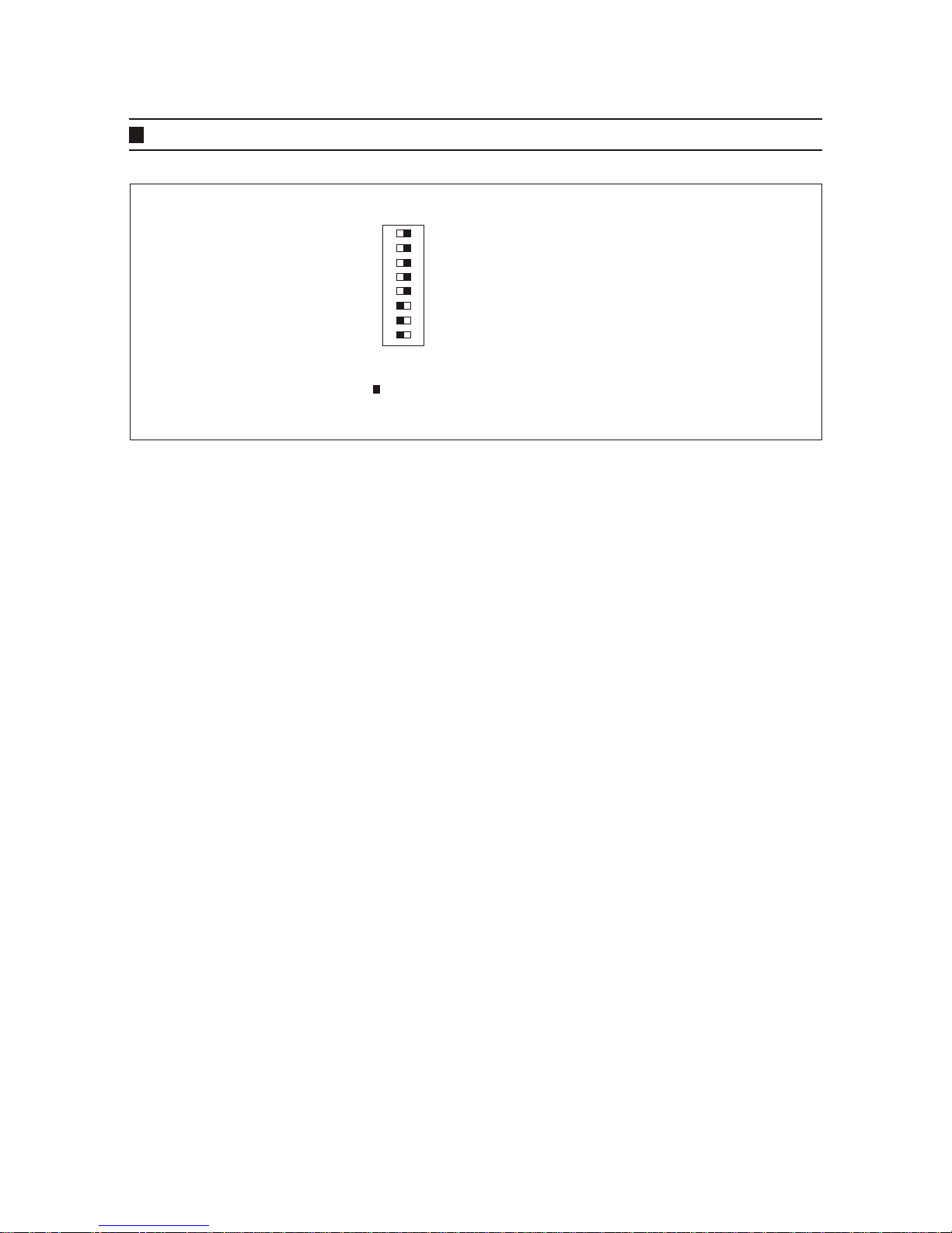
,QWHUQDODQG/LQH/RFN6\QF
,QWHUQDO0RGHLVQRUPDOO\XVHGZKHQFRQQHFWLQJWRDPRQLWRU TXDGSURFHVVRU,
PXOWLSOH[HU'95HWF/LQHORFNPRGHLVXVHGWRV\QFKURQL]HDJURXSRI
FDPHUDVWRWKH$&SRZHUVRXUFHWRSUHYHQWWKHSLFWXUHIURPUROOLQJRQEDVLF
VZLWFKHUXQLWV
)/./)OLFNHUOHVV
,I$&SRZHUIUHTXHQF\FKDQJHVWKHIOLFNHURIIOXRUHVFHQWOLJKWFDQEHYLVLEOH
RQWKHPRQLWRU(QDEOHWKLVPRGHWRSUHYHQWWKLV
$*&$XWR*DLQ&RQWURO
7KLVZLOOLQFUHDVHWKHVHQVLWLYLW\RIWKHFDPHUDE\DPSOLI\LQJWKHYLGHRVLJQDO
LQORZOLJKWFRQGLWLRQVWRSURYLGHEHWWHUORZOLJKWSLFWXUHV
%/&%DFN/LJKW&RPSHQVDWLRQ
,QFUHDVHVWKHEULJKWQHVVRIGDUNREMHFWVDJDLQVWDEULJKWEDFNJURXQGWRKHOS
LGHQWLI\LWVIHDWXUHV
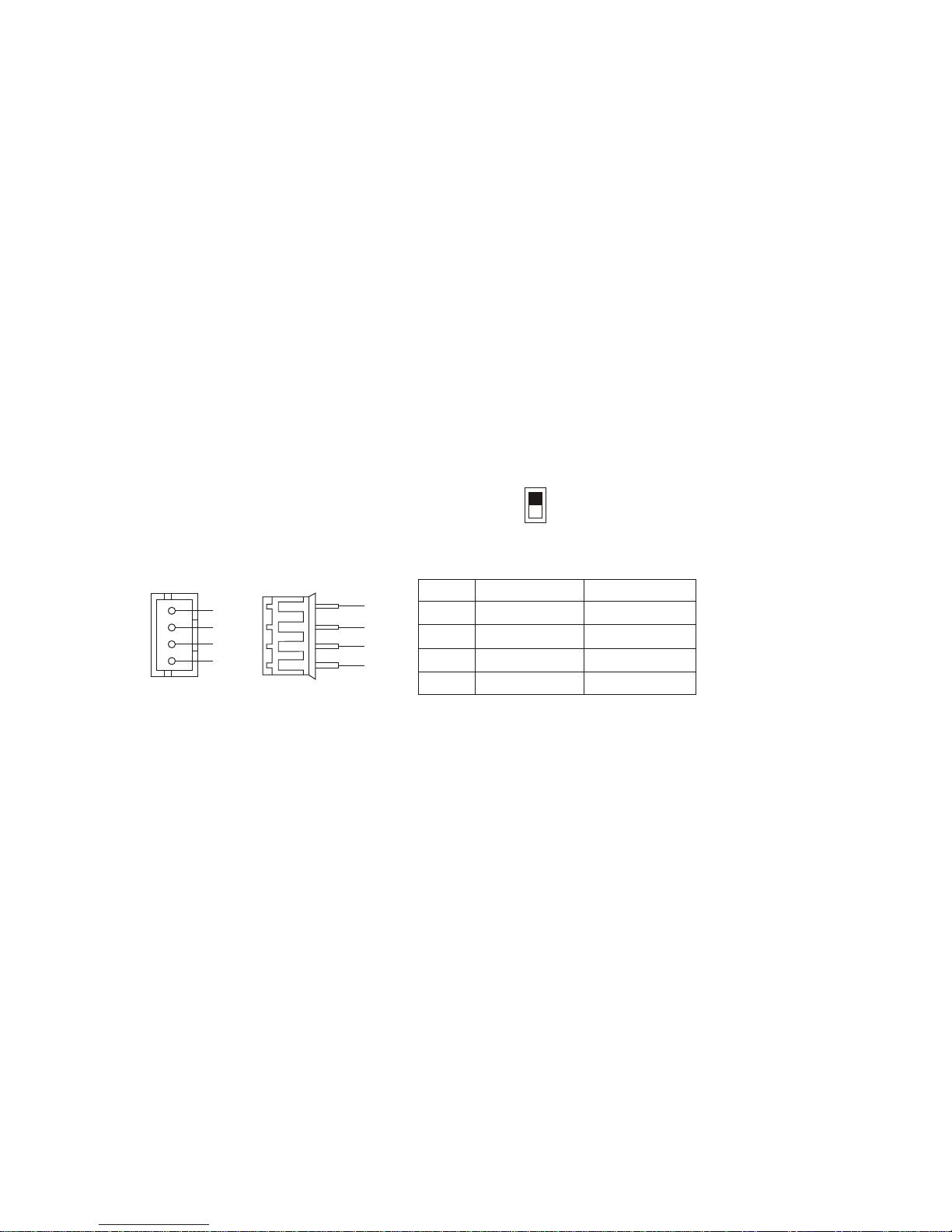
0:%0DQXDO:KLWH%DODQFH
7KLVPRGHDOORZVPDQXDOFRQWURORIWKHFRORUV7XUQ:%DQG:%2Q
7XUQ:%2II8VHWKHSKDVHXSGRZQVHOHFWLRQEXWWRQVVHHSDJH
WRDGMXVWWKHFRORU$IWHUDGMXVWLQJWXUQ:%RII
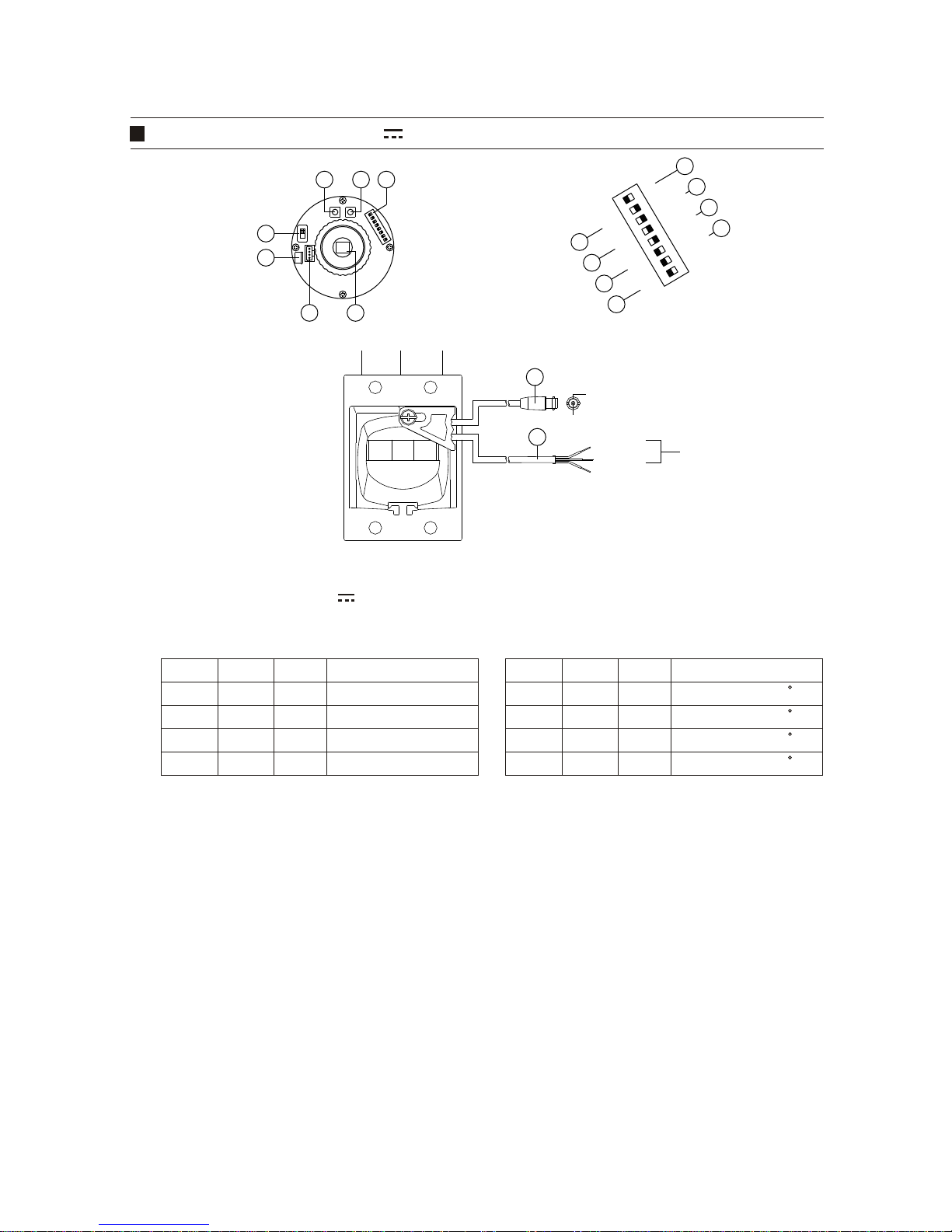
,ULV/HQV&RQWURO
9LGHROHQVLVFRQWUROOHGZLWK95LQOHQVDQG'&OHQVLVFRQWUROOHGZLWK
'&/(9(/95DWWKHIXQFWLRQFRQWUROERDUG

,167$//$7,21
,QLWLDOFKHFN
&KHFNDOOWKHFRQWUROVHWWLQJLQVLGHWKHFDPHUDEHIRUHLQVWDOOLQJLWWRHQVXUHD
VPRRWKWURXEOHIUHHLQVWDOODWLRQ
0RXQWLQJWKHEUDFNHW
&RQQHFWWKHFDPHUDWRWKHPRXQWLQJEUDFNHW
&RQQHFWLQJWKH&DEOH
9LGHRRXWSXWFDEOH
9LGHRFDEOHWRPRQLWRU'95HWF
6OLGHWKHVKULQNDEOHWXELQJRYHUERWKFRQQHFWRUVDQGDSSO\KHDW
$SSO\DVLOLFRQVHDODQWWRERWKHQGVRIWKHVKULQNDEOHWXELQJ
3ODFHDSLHFHRIVKULQNDEOHWXELQJRYHU
WKHYLGHRFDEOH
+($7,1*
PP RYHU PP RYHU
&RQQHFWRU
0ROGLQJ3DUW
6,/,&216($/$17
&RQQHFWLQJWKH9LGHRRXW
3RZHU&DEOH

-8-
3 - 2. Connecting the Power
Connect the appropriate cable to the power cable of the camera.
Referring to the specified label of the camera.
(Be sure to match the correct polarityin case of 12V DC)
Insert the cable into the shrinkable
tube A which shall be around 10mm
and tube B which shall be around 3mm.
After heating the three shrinkable tube B, as shown on the above, put the
shrinkable tube A as the drawing above. The tube should cover the edge of the
connection parts at least over 5mm and shrink it finally with heat. Apply a silicon
sealant to each ends of the shrinkable tube and shrink it finally with heat.
Heat the shrinkable tube B after connecting each wire. Be sure to match the correct
polarity in case of 12V DC.
Shrinkable Tube A Shrinkable Tube B
Power Cable
Power Cable
RED(12VDC+) OR 24VAC(~)
GREEN(COMMON GND)
BLACK(12VDC-)OR 24VAC(~)
SHRINKABLE TUBE
SILICON SEALANT
Shrinkable Tube B
Shrinkable Tube A
Shrinkable Tube B
Shrinkable Tube A
HEATING
INSTALLATION
5mm over

-9-
Locate it in a proper place, after inserting the sliding groove part of the sunvisor
into the rail of holder stand, and then tighten the fixed bolt to fix it.
FIXED BOLT
RAIL RAIL
HOLDER
STAND
INSTALLATION
4. Sunshield Installation
SUNSHIELD
GROOVE
This manual suits for next models
3
Table of contents
Other Rugged CCTV Security Camera manuals

Rugged CCTV
Rugged CCTV Night Scout TVI User manual

Rugged CCTV
Rugged CCTV stainless steel dome camera User manual

Rugged CCTV
Rugged CCTV SCOUT III User manual

Rugged CCTV
Rugged CCTV Ruff Ride User manual

Rugged CCTV
Rugged CCTV PLATINUM 622 User manual

Rugged CCTV
Rugged CCTV PATC-G4028 User manual

Rugged CCTV
Rugged CCTV Vanguard-700 User manual

Rugged CCTV
Rugged CCTV Sentry-700 User manual

Rugged CCTV
Rugged CCTV Night Ranger User manual

Rugged CCTV
Rugged CCTV TagShot III-27' User manual


