Ruide Disteo 23 User manual

USER MANUAL
Version: 17-11

1
Thank you for choosing RUIDE theodolite Disteo 23.
Please read the user manual carefully before use.
1. PRECAUTIONS
a. Do not collimate the objective lens directly to the
sunlight without a filter.
b. Do not store the instrument in extremely high or
low temperature, to avoid the sudden or great
change of temperature.
c. When the instrument is not in use, store it in the
case and avoid shock, dust and humidity.
d. If there is great difference between the
temperature in work site and that in store place,
you should leave the instrument in the case till it
adapts to the temperature of environment.
e. If the instrument has not been used for a long
time, you should remove the battery for separate
storage. The battery should be charged once a
month.
f. When transporting the instrument should be
placed in its carrying case, it is recommended that
cushioned material should be used around the
case for support.
g. For better accuracy, the instrument should be set
up on a wooden tripod rather than an aluminum
tripod.
h. Clean exposed optical parts with degreased
cotton or less tissue only!
i. Clean the instrument surface with a woolen cloth
after use. If it gets wet, dry it immediately.
j. Before opening, inspect the power, functions and
indications of the instrument as well as its initial
setting and correction parameters.
k. Unless the user is a maintenance specialist, do not
attempt to disassemble the instrument by yourself
even if you find the instrument abnormal.
l. Do not aim the laser beam to eyes.
m. Keep the screen clean. Do not scratch the screen
with sharp objects.

2
MENU
1. PRECAUTIONS........................................................................ 1
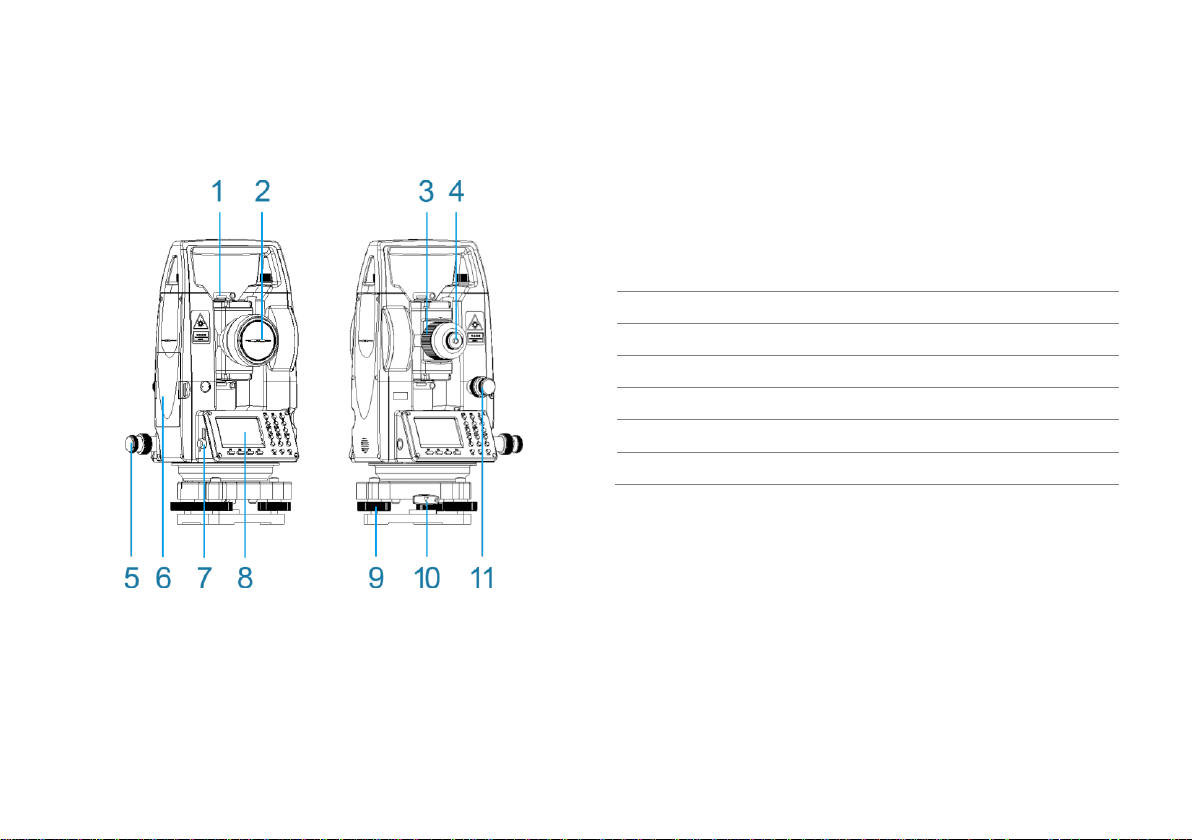
2. PART NAMES........................................................................... 3
3. OPERATION............................................................................. 4
3.1 Keys............................................................................ 4
3.2 Abbreviation................................................................ 5
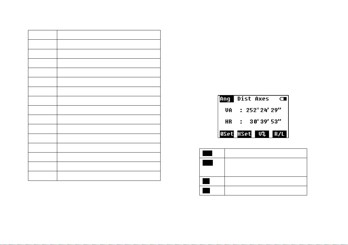
4. ANGLE MEDASUREMENT...................................................... 5
4.1 Angle .......................................................................... 5
4.2 HSet............................................................................ 6
5. DISTANCE MEASUREMENT................................................... 6
5.1 Distance...................................................................... 6
5.2 Stake Out (S.O.) ......................................................... 7
5.3 Mode........................................................................... 7
6. AXES STAKE-OUT................................................................... 8
6.1 Stake Out of One Side on the Axes............................ 8
6.2 Stake Out of Any Point ............................................... 9
7. QUICK SETTING.................................................................... 10
7.1 Laser Plummet ......................................................... 10
7.2 Laser Pointer ............................................................ 11
7.3 Compensation on X .................................................. 11
7.4 Distance Setting ....................................................... 11
7.5 Backlight and Sound .................................................11
8. SETTING.................................................................................12
8.1 Unit............................................................................12
8.2 Angle .........................................................................12
8.3 Distance ....................................................................12
8.4 PPM ..........................................................................12
8.5 Power ........................................................................13
9. CALIBRATION ........................................................................13
9.1 Calibrate i Angle ........................................................13
9.2 Correction of Additive Constant.................................14
10. INFORMATION...................................................................15
10.1 Firmware Upgrade ....................................................15
10.2 Factory Mode ............................................................16
10.3 System Information ...................................................16
11. SPECIFICATION ................................................................17
12. ERROR CODE ...................................................................18

3
2. PART NAMES
1. Collimator
2. Objective Lens
3. Focusing Screw
4. Telescope Eyepiece
5.
Horizontal Tangent Screw
6. Battery
7. RS232 Interface
8. Screw and Keyboard
9. Tribrach
10. Tribrach Lock
11. Vertical Tangent Screw

4
3. OPERATION
3.1 Keys
Keys
Function
Shift among 3 main functions
Menu
Power
1
Number 1
Shortcut to open laser plummet
2
Number 2
Shortcut to open laser pointer
3
Number 3
Shortcut to open compensation on Axis X (N)
4
Number 4
Shortcut to open setting of distance measurement
5
Number 4
Shortcut to open setting of backlight and sound
6-9,0
Number 6, 7, 8, 9, 0
ESC
Enter
Move up and down
Turn page
-/.
Input –or .

5
3.2 Abbreviation
VA
vertical angle
HA
horizontal angle
V%
shift degree and slope
HL/HR
horizontal left/right angle
VD
vertical distance
HD
horizontal distance
SD
slope distance
hPa
unit of air pressure: hectopascal
mmHg
unit of air pressure: millimeter of mercury
inHg
unit of air pressure: inch of mercury
m
unit of distance: meter
ft
unit of distance: feet
gon
unit of angle
mil
unit of angle
°C
unit of temperature: degree Celsius
°F
unit of temperature: degree Fahrenheit
4. ANGLE MEDASUREMENT
The function of angle measurement covers
measuring and displaying vertical and horizontal
angles (VA and HL/HR), 0 set, horizontal set (HSet),
switching to slope (V%), switching Face Right and
Face Left (R/L), etc.
4.1 Angle
0Set:
Set the current angle to 0°.
HSet:
Input an angle to set as the
current horizontal angle.
V%:
Shift degree and slope.
R/L:
Shift Face Left and Face Right.

6
4.2 HSet
Press HSet to go the screen of setting horizontal
angel.
Input a value of the angle to set as the current
horizontal angle. And press OK to confirm.
5. DISTANCE MEASUREMENT
The function of distance measurement covers
measuring and displaying vertical distance (VD),
horizontal distance (HD), slope distance (SD), stake
out (S.O.), and setting of measuring mode (Mode),
etc.
5.1 Distance
Aim at the center of the target prism through the
optical eyepiece by adjusting the focus, and
press Meas to start the distance measurement.
Meas:
Start to measure the distance.
S.O.:
Start to stake out the distance.
Mode:
Setting of the measuring mode

7
5.2 Stake Out (S.O.)
Input a distance to stake out. It could be a
vertical distance, horizontal distance or slope
distance, by pressing Shft to shift.
Shft:
shift the distance type to stake out
←:
delete
→:
move right
S.O.:
Save the input value and continue
to stake out.
Display of Stake Out Result
VD:
The distance difference between
the current horizontal distance
and the horizontal distance
about to stake out.
5.3 Mode
This setting is to change the mode of
measurement.

8
6. AXES STAKE-OUT
This session is to introduce the stake-out of the
point by entering the offset to a baseline.
There’re 2 options to define the baseline. One is
to define by station point and a known bearing
angle (0°00’00”), one is to define by two new
points.
Press F1 or F2 to select.
6.1 Stake Out of One Side on the Axes
Step 1: Set the theodolite at Point A.
Step 2: Aim at the prism which is set at Point B
and press OSET to set it to 0°.
Step 3: Input the distance value of the line along
Point A to B, and the offset value.
Line
Offset value along the axes of
Point A to B.
Offst
Offset value perpendicular to
the axis.

9
Step 4: Press F1 to measure. Indicate the
poleman to move the prism according to the
indications on the screen, until all the values on
the screen are 0.
H Diff
the angle difference between
the HA of Point A to staking out
point and the HA of current
target
+↑/-↓
offset of perpendicular to the axis
+L/-R
offset along the axis
SwPt
Return to input offset to start a
new point.
6.2 Stake Out of Any Point
This is the stake out provided that the theodolite
is set at any point outside the axis.
Select F2.
Step 1: Measure the distance to Point A and B,
then press F4 to next step.

10
Step 2: Input the line and offset values, press F4
to next step.
Step 3: Press F1 to measure. Indicate the
poleman to move the prism according to the
indications on the screen, until all the values on
the screen are 0.
7. QUICK SETTING
There’re 5 settings in QuickSet: laser plummet, laser
pointer, compensation on X axes, distance setting,
backlight and sound.
7.1 Laser Plummet
It is to open the laser plummet fast. You can also

11
set the brightness grade.
7.2 Laser Pointer
Press F2 to turn on laser pointer.
7.3 Compensation on X
To turn on and off the compensation on X axis,
and check the tilt value.
7.4 Distance Setting
To set various settings of distance measurement.
7.5 Backlight and Sound
To set the screen backlight, beep of pressing
key, crosshair backlight.

12
8. SETTING
It covers 5 settings: unit, angle, distance, PPM,
and power.
8.1 Unit
To set the units of angle, distance, temperature
and air pressure.
8.2 Angle
To set the display of vertical angle.
8.3 Distance
To set various parameters of distance.
Scale
Scale factor
Ht
Elevation of the station
point
8.4 PPM
To set parameters related to temperature and
air pressure.

13
8.5 Power
To set parameters related to power.
SlepTime
Time to enter to sleep
mode if no operation.
Off Time
Time to power off if no
operation.
9. CALIBRATION
This program is to calibrate the errors and correct
additive constant.
9.1 Calibrate i Angle
i angle is also referred to the vertical index
difference.
Step 1: On Face Left, collimate the crosshair
center in a collimator, and adjust the focus until
it is clear. Press OK to proceed to next step.

14
Step 2: Turn the theodolite to Face Right, and
collimate the crosshair center in the collimator
until it is clear. Press OK to proceed to next step.
Step 3: The index difference will be shown. Press
OK to confirm to calibrate. Caution: If the
difference is too big, it will suggest resetting the
i angle. Press OK to continue, or Back to return
to calibrate again.
Tips: Repeat the calibration of i angle according
to 3 steps above if necessary.
9.2 Correction of Additive Constant
Caution: Do not change the constant if
unnecessary.
The additive constant is relatively stable. We
suggest inspecting it once or twice a year. You
can follow the following steps to do a quick
inspection and correction.
Inspection
Step 1: Set the instrument on a flat ground, mark
it as Point A. Along the vertical crosshair, mark
Point B and C with a space of 50m on the same
line. Set reflectors on Point B and C precisely.
Step 2: Set the temperature and air pressure in
the system, and measure the horizontal
distances of AB and AC accurately.
Step 3: Set the theodolite on Point B and level it
precisely. Measure the horizontal distance of BC
accurately.
Step 4: Now we can get the additive constant
by the following formula.
K=AC-(AB+BC)

15
K should be close to 0. If |k|>5mm, the
theodolite should be delivered to professional
workshop which has standard alignment to
calibrate.
Correction
According to the formula, input the K value in
the following screen.
10. INFORMATION
Here you can upgrade firmware and check the
system information.
10.1Firmware Upgrade
Firmware upgrade includes the upgrade of
angle system and distance system.
It is required to connect the theodolite with
computer via RS232 serial interface.

16
Angle Upgrade
Distance Upgrade
System Upgrade
Hold key 1, and press power to enter to system
upgrade. Follow the operation on PC
upgrading software.
10.2 Factory Mode
To reset to default setting. Input the password to
proceed.
10.3 System Information
You can check the model, serial number,
product number, system version, distance
version and angle version on it.

17
11. SPECIFICATION
TELESCOPE
Image
Erect
Magnification
26.5X
Aperture (telescope)
40mm
Aperture (distance)
45mm
Resolution
3”
Field of View
1°30”
Min. Focusing
1.5m
Length
155mm
LASER
Wave Length
635+20nm
Class
II
Diameter of Laser Dot
≤5mm/100m
Accuracy
≤10”
ANGLE
Type
Absolute Encoding
Diameter of Disk
79mm
Detecting Method
Horizontal: dual; Vertical: dual
DISTANCE
Reflecting Target
Single Prism
Range
300m
Accuracy
+(3mm+2ppm*D)
Time
Continuous: 0.35s; Fine: 1.5s
Atmospheric Correction
Manual input, auto correct.
Prism Constant Corr.
Manual input, auto correct.
LEVEL
Plate Vial
30”/2mm
Circular Vial
8’/2mm
COMPENSATOR
Type
Single Axis
Range
+3’
Resolution
3”
LASER PLUMMET
Type
Class II visible red laser
Wave of Length
635+20nm
Accuracy
1.5mm (when HT 1.5m)
Diameter
2.5mm (when HT 1.5m)
DISPLAY
Type
160*96 Dot Matrix
Size
2.7 inch
POWER

18
Type
Li-on
Voltage
7.4V
Working Time
8h
ENVIRONMENT
Working Temperature
-20°C - +50°C
SIZE & WEIGHT
Size
165 X 160 340 mm
Weight
4.7kg
12. ERROR CODE
Category
Message
Angle Problem
UpperV ERR
LowerV ERR
HL ERR
HR ERR
V CCD Error
H CCD Error
V Rotate ERR
H Rotate ERR
Distance Problem
ERR32
ERR33
ERR35
ERR38
ERR41
Restart the theodolite. If it is not solved, return to your local
dealer for further inspection.
Table of contents
Other Ruide Measuring Instrument manuals