Rupert Neve Designs 5060 CENTERPIECE User manual

Operations Manual
5060 CENTERPIECE
24 X 2 DESKTOP MIXER
the

2
5060: 24x2 Desktop Mixer User Guide
Thank you for your purchase of a 5060 Desktop Mixer.
Everyone at Rupert Neve Designs hope you enjoy using this tool as much as we have enjoyed
designing and building it. Please take note of the following list of safety concerns and power
requirements before using the 5060 module.
Safety
It’s usual to provide a list of “do’s and dont’s” under this heading but mostly these amount to
common sense issues. However, here are important safety requirements that must be adhered to:
1) Read these instructions.
2) Keep these instructions.
3) Heed all warnings.
4) Follow all instructions.
5) Do not use this apparatus near water.
6) Clean only with a dry cloth.
7) Do not block any ventilation openings. Install in accordance with the manufacturer’s instructions.
8) Do not install near any heat source such as radiators, heat registers, stoves, or other apparatus (includ-
ing ampliers) that produce heat.
9) Do not defeat the safety purpose of the polarized or grounding-type plug. A polarized plug has two
blades with one wider than the other. A grounding type plug has two blades and a third grounding
prong. The wide blade or the third prong are provided for your safety. If the provided plug does not t
into your outlet, consult an electrician.
10) Protect the power cord from being walked on or pinched, particularly at plugs convenience recep-
tacles and at the point where the cord exits from the apparatus.
11) Only use attachments/accessories specied by the manufacturer.
12) Unplug this apparatus during lightning storms or when unused for long periods of time.
13) Refer all servicing to qualied service personnel. Servicing is required when the apparatus has been
damaged in any way, such as when power-supply cord or plug is damaged, liquid has been spilled or
objects have fallen into the apparatus, the apparatus has been exposed to rain or moisture, does not op-
erate normally, or has been dropped.
14) Do not expose this apparatus to rain or moisture.
15) The apparatus shall be connected to a mains socket outlet with a protective earthing connection.
Heat generated by the module is radiated through the case work, and by a silent fan at the back of the
module. Ventilation holes should not be covered or blocked for any reason. To avoid overheating, 5060
units should not be stacked immediately above or adjacent to other equipment that get hot. Also bear
in mind that other equipment may radiate strong hum elds which could spoil the performance of your
5060.
Protect the power cord from being walked on or pinched, particularly at plugs convenience receptacles
and the point where they exit from the apparatus. Do not defeat the safety purpose of the polarized or
grounding-type plug. A polarized plug has two blades with one wider than the other. A grounding type
plug has two blades and a third grounding prong. The wide blade or the third prong are provided for
your safety. Unplug the module during lightning storms or when unused for long periods of time.

3
Don’t operate your 5060 module in or around water! Electronic equipment and liquids are not
good friends. If any liquid is spilled, such as soda, coffee, alcoholic or other drink, the sugars and
acids will have a very detrimental effect. Sugar crystals act like little rectiers and can produce
noise (crackles, etc.). SWITCH OFF IMMEDIATELY because once current starts to ow the
mixture hardens, can get very hot (burnt toffee!) and cause permanent and costly damage. If it gets
wet and you suspect that good clean water may have gotten in, immediately unplug the unit, and
remove it from the source of water. Please contact service as soon as possible at
5060 Block Diagram
StereoL
StereoR
GND
Soft Mute
StInL1+
StInL1-
StInR1+
StInR1-
InsInL1+
InsInL1-
InsInR1+
InsInR1-
Insert Return
ExtIn1L+
ExtIn1L-
ExtIn1R+
ExtIn1R-
EARTH
+V
GND
GND
Dim
Ext. I/P
Talkback
Mix Out
Monitor Section
GND
CW
CW
Stepped Attenuator
Mono Summing
Left VU
StInL1+
StInL1-
StInR1+
StInR1-
Talk1
Talk2
Talk1
Talk2
GND
Soft Mute
Insert Return
GND
Soft Mute
StInL1+
StInL1-
StInR1+
StInR1-
InsInL1+
InsInL1-
InsInR1+
InsInR1-
Insert Return
GND
Soft Mute
Insert Return
GND
LineIn9+
LineIn9-
GND
LineIn10+
LineIn10-
1-2
3-4
5-6
7-8
L INS RTNL INS SND
R INS RTN
R INS SND
Stereo Insert
Right VU
Variable Dim
EARTH
123
Mono/Left
Mono/Left
StInL1+
StInL1-
StInR1+
StInR1-
InsInL1+
InsInL1-
InsInR1+
InsInR1-
Talk1
Talk2
Talk1
Talk2
Mono/Left
StInL1+
StInL1-
StInR1+
StInR1-
StInL1+
StInL1-
StInR1+
StInR1-
InsInL1+
InsInL1-
InsInR1+
InsInR1-
Mono/Left
Insert Send
Insert Send
Insert Send
Insert Send
StInL1+
StInL1-
StInR1+
StInR1-
StInL1+
StInL1-
StInR1+
StInR1-
Inputs
TB to Send
TB to Send
Inputs
Inputs
Inputs
Texture
Texture
TB LVL
L
R
Ext. IP 1-3
Select
Typical, Stereo Input Channels 9-24
Talkback Remote
Control
TB OUT
TB assign
Send 1, 2
TB assign
Send 3, 4
(Activate by Grounding Tip)
Front Panel
Talk Button
(DIM Function Activates
when TALK is Active)
TB MIC
To DIM
TALK 1, 2
TALK 3, 4
J28

4
Power Requirements
Each 5060 unit has high quality, low noise switching power supplies that are further ltered and
regulated for an exceptionally quiet and reliable power source for the audio circuits. The power supply
is considered “universal” in the sense that it will accept 100V through 240V AC and with 50 or 60Hz.
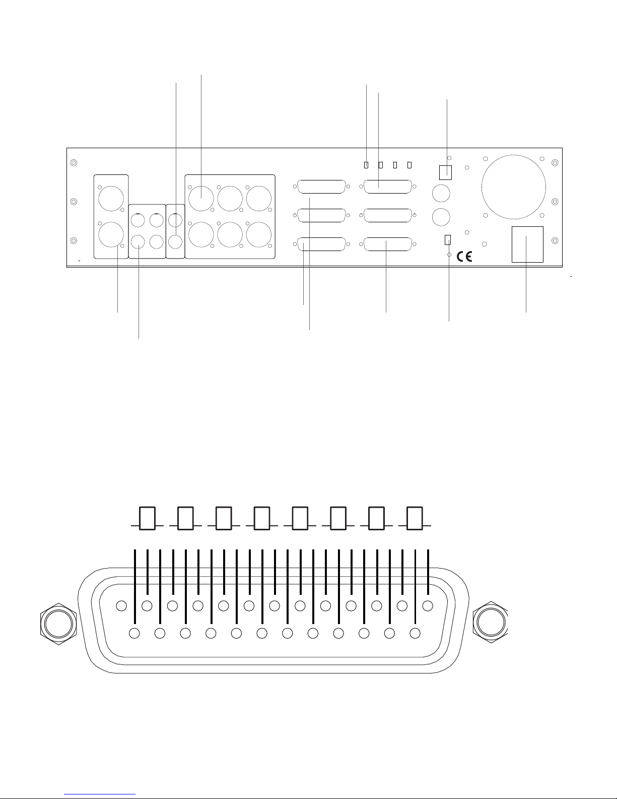
Be absolutely sure to disconnect mains power (remove the power cable from the IEC power connector
at the back panel) before servicing. The fuse is on the power supply and is not user accessible. The fuse
should only be replaced by a qualied service technician.
The fuse is a protection device intended to prevent additional damage or hazard if the 5060 unit
develops a problem. The symptom of a blown fuse is simply that the unit does not power up. If this
The Rupert Neve Designs 5060 Overview
From the father of the recording console comes the 5060 Centerpiece: the Class-A analog heart of your
21st-century studio. Sized for your desktop, the 5060 delivers the tonality and center section features
of Rupert’s agship 5088 console at your ngertips, cementing outboard together with serious custom
transformers, exible monitoring, DAW transport controls, and the raw power of a Rupert Neve-
designed 24×2 mix-buss.
With a modular, hybrid analogue/digital mix system built around the 5060, you can outt your studio
with exactly what you need – and nothing that you don’t. Utilizing modern DAW control technologies,
the 5060 seamlessly integrates stem outputs from the DAW with the rest of your control room, sums the
nal mix, and provides 2-track outputs, source selection, and speaker feed outputs from the monitor
section.
In the 5060, amplication is handled with fully class-A operational amplier topologies featuring
Rupert’s custom transformer designs. While these circuits share a lineage with the circuits used in
Rupert’s consoles from the 70’s, and in many ways sound similar, there are renements in noise, slew
rate, dynamic range and particularly avoidance of unpleasant high frequency distortion artifacts.
With proper implementation, the 5060 can redene the sonic possibilities and streamline workow in
the hybrid DAW and analogue based studio.
Quick Start: Configuration Suggestions for the 5060
The 5060 is designed to function both as a mixer, and as a way to tie together your studios analogue
and digital components. By conguring mix systems based around the 5060 and 5059 Satellite
Summing Mixers, any number of studio workows can be accommodated. While there is no “right”
way to connect the 5060, here are a few suggestions to get started:
The 5060 is designed to integrate your analogue components like outboard processing, speakers, and
headphone ampliers with the outputs from your DAW. Although one could conceivably use parts of
the 5060 in the pre DAW path, all of our suggestions use the 5060 entirely in the post DAW or “mix”
path. In the “Lone 5060” conguration, up to 12 separate stereo pairs (stems) can be outputted from
the DAW through the DAC and into the 5060 for analogue mixing. Stereo inputs 1-8 may also be used
as mono center channels to allow for latency free integration of analogue processing on key tracks like
lead vocals during mixing. Stereo sends may also be sent out of the DAW and into reverbs, delays, or
any processors for use as effects inputs to the mix buss with channels 9-24.

5
ADC
DAC
36
30
24
18
12
60dB 66
60
54
48
42
20Hz 250Hz
100
MIN MAX
TEXTURE
0dB
-6 +6
TRIM
GAIN
POWER
SILK
48V
HPF
HPF
MICPRE
+SILK
22
20
18
14
10
4
-2
-10
LEVEL
“The Lone 5060”
PEAK PEAK
∞0
MIN MAX
-30 -6
∞0
9-10 11-12 13-14 15-16 17-18 19-20 21-22 23-24
1-2 3-4 5-6 7-8
-50
-60
∞
-20
-10
-40
-25
-15
0
-5
+10
+5
0
-5
-10
-30
-40
-50
∞
-15
+10
+5
0
-5
-10
-30
-40
-50
∞
-15
+10
+5
0
-5
-10
-30
-40
-50
∞
-15
+10
+5
0
-5
-10
-30
-40
-50
∞
-15
MIX
STEREO INPUT CHANNELS 9 - 24
TB ASSIGN
MONITOR SELECT
HEADPHONE
MONITOR SOURCE
STEREO INPUT CHANNELS 1 - 8
RUPERT NEVE DESIGNS
MASTER MONITOR
TB LEVEL TEXTURE DIM LEVEL HEADPHONE
-10
-15
-5
-30
-20
∞0
-10
-15
-5
-30
-20
∞0
-10
-15
-5
-30
-20
∞0
-10
-15
-5
-30
-20
∞0
-10
-15
-5
-30
-20
∞0
-10
-15
-5
-30
-20
∞0
-10
-15
-5
-30
-20
∞0
-10
-15
-5
-30
-20
∞0
RED-SCRUB
GRN-SHUTTLE
MIC
5060 CENTERPIECE
TALK
DIM
MON 2 MON 3
EXT 3EXT 2
EXT 1
MIX
1/2 3/4 SILK
MON 1
MONO
INS MUTE INS MUTE INS MUTE INS INS
MUTE
MODE
24 x 2 Desktop Mixer
ADC
DAC
36
30
24
18
12
60dB 66
60
54
48
42
20Hz 250Hz
100
MIN MAX
TEXTURE
0dB
-6 +6
TRIM
GAIN
POWER
SILK
48V
HPF
HPF
Rupert Neve
Designs 511
MICPRE
+SILK
22
20
18
14
10
4
-2
-10
LEVEL
Headphone Mixer / Amp
Mono / Stereo Subwoofers
Cutting Room Playback
Third Pair of Speakers
Optional:
Supplemental Digital Control
Tablet Computers
Control Surfaces
Digital Faders / Rotary Encoders
Future Control Technology
Transport control
over Midi or USB
Mon 3 (Latchable)
Stereo Mix Output to 2-Track In
2-Track Output to Ext Monitor In
Stereo or Mono Channel
Insert Send and Returns
for Outboard Processing
Stereo Mix Insert
Send and Returns
for Outboard Processing
-15 +15
0
-15 +15
0
-15 +15
0
-6dB +20
100mS 2.5 S
250 1S
-30dB +20dB
-10 +10
GAIN
1.1:1 40:1
RATIO
1.5:1 3:1
FF
FB
LOPEAK
8K
16K
THRESH
S/CHPF
RELEASE
LINK
5mS 75mS
ATTACK
25 50
COMPIN
EQIN
EQPRE
POST
220
100
60
35
MIDFREQ
MIDHI Q
LOWFREQ
0
22
20
18
14
10
4
-2
-10
1
2
4
6
10
14
18
22
LevelGR
3K
1.5K
700
350
200
6K
HF
MID
LF
HIPEAK
HPF
Red120Hz
Blue60Hz
I
NDUCTOREQ
5051 EQ/Compressor
C
OMPRESSOR
LINE1
LINE2
-15 +15
0
-15 +15
0
-15 +15
0
-6dB +20
100mS 2.5 S
250 1S
-30dB +20dB
-10 +10
GAIN
1.1:1 40:1
RATIO
1.5:1 3:1
FF
FB
LOPEAK
8K
16K
THRESH
S/CHPF
RELEASE
LINK
5mS 75mS
ATTACK
25 50
COMPIN
EQIN
EQPRE
POST
220
100
60
35
MIDFREQ
MIDHI Q
LOWFREQ
0
22
20
18
14
10
4
-2
-10
1
2
4
6
10
14
18
22
LevelGR
3K
1.5K
700
350
200
6K
HF
MID
LF
HIPEAK
HPF
Red120Hz
Blue60Hz
I
NDUCTOREQ
5051 EQ/Compressor
C
OMPRESSOR
LINE1
LINE2
24
22
20
18
16
12
6
0
REDUCTION
OUTPUT
24
22
20
18
16
12
6
0
REDUCTION
OUTPUT
50
40
30
20 mS 80 mS
70
60
0.5
0.4
0.2
0.1 S 3.0 S
2.0
1.0
50
40
30
20mS 80mS
70
60
0.5
0.4
0.2
0.1 S 3.0 S
2.0
1.0
0
-8
-20
-30dB +20dB
+14
+8 2:1
1.5
1:1 40:1
5:1
3:1 2:1
1.5
1:1 40:1
5:1
3:1
0
Min Max
0
Mono Wide
Min
Max
18
15
12
10 Off
+24
21
+10
0 +20
50
0 100 Min Max
+10
0 +20
50
0 100 0
-8
-20
-30dB +20dB
+14
+8
18
15
12
10 Off
+24
21
2
4
6
8
10
12
18
24
2
4
6
8
10
12
18
24
PORTICO II
Master Buss
Processor
SFE
Depth
CHA
Width
CHB
SFE toCOMP
CHANNEL A RUPERT NEVE DESIGNS
FF
FB
SC
250 Hz
RMS
Peak
Comp
In
SC
Insert
SC
Insert
SC
250 Hz
LINK
FB
FF
RMS
Peak
Comp
In
Silk+ : Red
Silk : Blue
CHANNEL B
In In
Width EQDepth EQ
EQ EQ
WidthDepthRatio
Texture Limit dBu
Threshold
Blend %Limit dBu
Ratio
Silk+ : Red
Silk : Blue
Blend %
Threshold
Gain dB Texture Gain db
ReleaseAttackReleaseAttack
CH A Master
Depth Depth Width Width
CH BCH A
HF
HM
LM
LF
HF
HM
LM
LF
POWER
Equalizer
Comp Reverb 1
Reverb 2
Reverb 3
Delay
24
22
20
18
16
12
6
0
REDUCTION
OUTPUT
24
22
20
18
16
12
6
0
REDUCTION
OUTPUT
50
40
30
20 mS 80mS
70
60
0.5
0.4
0.2
0.1 S 3.0S
2.0
1.0
50
40
30
20mS 80mS
70
60
0.5
0.4
0.2
0.1 S 3.0S
2.0
1.0
0
-8
-20
-30dB +20dB
+14
+8 2:1
1.5
1:1 40:1
5:1
3:1 2:1
1.5
1:1 40:1
5:1
3:1
0
Min Max
0
Mono Wide
Min
Max
18
15
12
10 Off
+24
21
+10
0 +20
50
0 100 Min Max
+10
0 +20
50
0 100 0
-8
-20
-30dB +20dB
+14
+8
18
15
12
10 Off
+24
21
2
4
6
8
10
12
18
24
2
4
6
8
10
12
18
24
PORTICO II
Master Buss
Processor
SFE
Depth
CHA
Width
CHB
SFEto COMP
CHANNEL A RUPERT NEVE DESIGNS
FF
FB
SC
250Hz
RMS
Peak
Comp
In
SC
Insert
SC
Insert
SC
250Hz
LINK
FB
FF
RMS
Peak
Comp
In
Silk+: Red
Silk: Blue
CHANNEL B
In In
Width EQDepth EQ
EQ EQ
WidthDepthRatio
Texture Limit dBu
Threshold
Blend %Limit dBu
Ratio
Silk+: Red
Silk: Blue
Blend %
Threshold
Gain dB Texture Gain db
ReleaseAttackReleaseAttack
CHA Master
Depth Depth Width Width
CH BCH A
HF
HM
LM
LF
HF
HM
LM
LF
POWER
L R
L R
LEVEL
LEVEL
PAN
PAN
INSERT
INSERT
STEREO2
STEREO2
-10
-15
-3
-30
-20
∞0
-10
-15
-3
-30
-20
∞0
MIN MAX
TEXTURE
MIN MAX
TEXTURE
STEREO1
STEREO2
SIGNAL
SIGNAL
Silk+: Red
Silk: Blue
Silk+: Red
Silk: Blue
1 2 3 4 5 6 7 8
9 16151413121110
RUPERT NEVE DESIGNS
16 x 2+2
Summing
Mixer
5059
POWER
L R
L R
LEVEL
LEVEL
PAN
PAN
INSERT
INSERT
STEREO2
STEREO2
L R
L R
LEVEL
LEVEL
PAN
PAN
INSERT
INSERT
STEREO2
STEREO2
L R
L R
LEVEL
LEVEL
PAN
PAN
INSERT
INSERT
STEREO2
STEREO2
L R
L R
LEVEL
LEVEL
PAN
PAN
INSERT
INSERT
STEREO2
STEREO2
L R
L R
LEVEL
LEVEL
PAN
PAN
INSERT
INSERT
STEREO2
STEREO2
L R
L R
LEVEL
LEVEL
PAN
PAN
INSERT
INSERT
STEREO2
STEREO2
L R
L R
LEVEL
LEVEL
PAN
PAN
INSERT
INSERT
STEREO2
STEREO2
SATELLITE
-4
-10
-20
∞+10
0
+6
-30
-4
-10
-20
∞+10
0
+6
-30
-4
-10
-20
∞+10
0
+6
-30
-4
-10
-20
∞+10
0
+6
-30
-4
-10
-20
∞+10
0
+6
-30
-4
-10
-20
∞+10
0
+6
-30
-4
-10
-20
∞+10
0
+6
-30
-4
-10
-20
∞+10
0
+6
-30
-4
-10
-20
∞+10
0
+6
-30
-4
-10
-20
∞+10
0
+6
-30
-4
-10
-20
∞+10
0
+6
-30
-4
-10
-20
∞+10
0
+6
-30
-4
-10
-20
∞+10
0
+6
-30
-4
-10
-20
∞+10
0
+6
-30
-4
-10
-20
∞+10
0
+6
-30
-4
-10
-20
∞+10
0
+6
-30
L R
L R
LEVEL
LEVEL
PAN
PAN
INSERT
INSERT
STEREO2
STEREO2
-10
-15
-3
-30
-20
∞0
-10
-15
-3
-30
-20
∞0
MIN MAX
TEXTURE
MIN MAX
TEXTURE
STEREO1
STEREO2
SIGNAL
SIGNAL
Silk+: Red
Silk: Blue
Silk+: Red
Silk: Blue
1 2 3 4 5 6 7 8
9 16151413121110
RUPERT NEVE DESIGNS
16 x 2+2
Summing
Mixer
5059
POWER
L R
L R
LEVEL
LEVEL
PAN
PAN
INSERT
INSERT
STEREO2
STEREO2
L R
L R
LEVEL
LEVEL
PAN
PAN
INSERT
INSERT
STEREO2
STEREO2
L R
L R
LEVEL
LEVEL
PAN
PAN
INSERT
INSERT
STEREO2
STEREO2
L R
L R
LEVEL
LEVEL
PAN
PAN
INSERT
INSERT
STEREO2
STEREO2
L R
L R
LEVEL
LEVEL
PAN
PAN
INSERT
INSERT
STEREO2
STEREO2
L R
L R
LEVEL
LEVEL
PAN
PAN
INSERT
INSERT
STEREO2
STEREO2
L R
L R
LEVEL
LEVEL
PAN
PAN
INSERT
INSERT
STEREO2
STEREO2
SATELLITE
-4
-10
-20
∞+10
0
+6
-30
-4
-10
-20
∞+10
0
+6
-30
-4
-10
-20
∞+10
0
+6
-30
-4
-10
-20
∞+10
0
+6
-30
-4
-10
-20
∞+10
0
+6
-30
-4
-10
-20
∞+10
0
+6
-30
-4
-10
-20
∞+10
0
+6
-30
-4
-10
-20
∞+10
0
+6
-30
-4
-10
-20
∞+10
0
+6
-30
-4
-10
-20
∞+10
0
+6
-30
-4
-10
-20
∞+10
0
+6
-30
-4
-10
-20
∞+10
0
+6
-30
-4
-10
-20
∞+10
0
+6
-30
-4
-10
-20
∞+10
0
+6
-30
-4
-10
-20
∞+10
0
+6
-30
-4
-10
-20
∞+10
0
+6
-30
PEAK PEAK
∞0
MIN MAX
-30 -6
∞0
9-10 11-12 13-14 15-16 17-18 19-20 21-22 23-24
1-2 3-4 5-6 7-8
-50
-60
∞
-20
-10
-40
-25
-15
0
-5
+10
+5
0
-5
-10
-30
-40
-50
∞
-15
+10
+5
0
-5
-10
-30
-40
-50
∞
-15
+10
+5
0
-5
-10
-30
-40
-50
∞
-15
+10
+5
0
-5
-10
-30
-40
-50
∞
-15
MIX
STEREO INPUT CHANNELS 9 - 24
TB ASSIGN
MONITOR SELECT
HEADPHONE
MONITOR SOURCE
STEREO INPUT CHANNELS 1 - 8
RUPERT NEVE DESIGNS
MASTER MONITOR
TB LEVEL TEXTURE DIMLE VEL HEADPHONE
-10
-15
-5
-30
-20
∞0
-10
-15
-5
-30
-20
∞0
-10
-15
-5
-30
-20
∞0
-10
-15
-5
-30
-20
∞0
-10
-15
-5
-30
-20
∞0
-10
-15
-5
-30
-20
∞0
-10
-15
-5
-30
-20
∞0
-10
-15
-5
-30
-20
∞0
RED-SCRUB
GRN-SHUTTLE
MIC
5060 CENTERPIECE
TALK
DIM
MON 2 MON 3
EXT 3EXT 2
EXT 1
MIX
1/2 3/4 SILK
MON 1
MONO
INS MUTE INS MUTE INS MUTE INS INS
MUTE
MODE
24 x 2 Desktop Mixer
ADC
DAC
36
30
24
18
12
60dB 66
60
54
48
42
20Hz 250Hz
100
MIN MAX
TEXTURE
0dB
-6 +6
TRIM
GAIN
POWER
SILK
48V
HPF
HPF
Rupert Neve
Designs 511
MICPRE
+SILK
22
20
18
14
10
4
-2
-10
LEVEL
Headphone Mixer / Amp
Optional:
Supplemental Digital Control
Tablet Computers
Control Surfaces
Digital Faders / Rotary Encoders
Future Control Technology
Transport control
over Midi or USB
.
Stereo or Mono Channel
Insert Send and Returns
for Outboard Processing
Stereo Mix Insert
Send and Returns
for Outboard Processing
Stereo or Mono Channel
Insert Send and Returns
for Outboard Processing
“5059’s Mixing into a 5060”
Mono / Stereo Subwoofers
Cutting Room Playback
Mon 3 (Latchable)
or
Dual Stereo Outputs with Different Silk & Texture Settings Dual Stereo Outputs with Different Silk & Texture Settings
Stereo Mix Output to 2-Track In
2-Track Output to Ext Monitor In
Rupert Neve
Designs 543
0
-8
-30 +20
+8
2:1
1.1:1 40:1
8:1
4:1
50
20mS 75mS
400
100mS 2.5 S
+4
0
-6 +20
+8
22
18
14
10
6
4
2
0
PEAK
RMS
HPF
S/C
F/F
F/B
GR
LEVEL
THRESHOLD
RATIO
ATTACK 1
2
4
6
10
14
18
22
IN
RELEASE
MAKE-UPGAIN
LINK
Rupert Neve
Designs 542
0dB
-12 +12
50%
0 100%
MIN MAX
22
20
18
14
10
4
-2
-10
8
7
6
5
4
3
2
1
SILKBLUE
SILKRED
30
15
IN
TAPE
EFFECT
POWER
LEVEL
DRIVE
IPS
SATURATION
TRIM
TEXTURE
BLEND
MIN MAX
TAPE
EMULATOR
36
30
24
18
12
60dB 66
60
54
48
42
0
-6 +6
220
100
60
35
25
12
6.8
4.7
40
20mS 80mS
60
200
100
80 1.6K
700
400
0.3
0.1 S 3.0 S
1.5
2.0
1.0
0.8 16
7.0
4.0
0
-15 +15
0
-15 +15
0
-15 +15
0
-15 +15
100
20Hz 250Hz
2.5
2:1
1.5
1:1 40:1
5:1
3:1
Min Max
2
0.7 5 Off Max
0 100
0
-6 +20
+8
2
0.7 5
Trim LF LMF HMF HF
Attack
Release
RMS
Peak
Comp
In
FF
FB
Blend % Gain dB
Threshold Ratio
Power
Silk : Red
Silk : Blue
Texture
PORTICO II RUPERT NEVE DESIGNS
REDUCTION
OUTPUT
Hz Hz kHz kHz
Shelf
PeakHF InLMF/HMF
Shelf
Peak
In
Q De-essQ
LF In
dB dB dBdB
All EQ
In Post
Comp
HPF
In S/C
HPF
Mic/DI
Line Phase Mute
Signal
dB
Thru
DI
+48V
Mic Gain HPF
PORTICO II
C H A N N E L
GND
LIFT
0
-8
-12
-30dB +20dB
+12
+8
2
4
6
8
10
12
18
24
24
22
20
18
16
12
6
0
Rupert Neve
Designs 543
0
-8
-30 +20
+8
2:1
1.1:1 40:1
8:1
4:1
50
20mS 75mS
400
100mS 2.5 S
+4
0
-6 +20
+8
22
18
14
10
6
4
2
0
PEAK
RMS
HPF
S/C
F/F
F/B
GR
LEVEL
THRESHOLD
RATIO
ATTACK 1
2
4
6
10
14
18
22
IN
RELEASE
MAKE-UPGAIN
LINK
36
30
24
18
12
60dB 66
60
54
48
42
0
-6 +6
220
100
60
35
25
12
6.8
4.7
40
20mS 80mS
60
200
100
80 1.6K
700
400
0.3
0.1 S 3.0 S
1.5
2.0
1.0
0.8 16
7.0
4.0
0
-15 +15
0
-15 +15
0
-15 +15
0
-15 +15
100
20Hz 250Hz
2.5
2:1
1.5
1:1 40:1
5:1
3:1
Min Max
2
0.7 5 Off Max
0 100
0
-6 +20
+8
2
0.7 5
Trim LF LMF HMF HF
Attack
Release
RMS
Peak
Comp
In
FF
FB
Blend % Gain dB
Threshold Ratio
Power
Silk : Red
Silk : Blue
Texture
PORTICO II RUPERT NEVE DESIGNS
REDUCTION
OUTPUT
Hz Hz kHz kHz
Shelf
PeakHF InLMF/HMF
Shelf
Peak
In
Q De-essQ
LF In
dB dB dBdB
All EQ
In Post
Comp
HPF
In S/C
HPF
Mic/DI
Line Phase Mute
Signal
dB
Thru
DI
+48V
Mic Gain HPF
PORTICO II
C H A N N E L
GND
LIFT
0
-8
-12
-30dB +20dB
+12
+8
2
4
6
8
10
12
18
24
24
22
20
18
16
12
6
0

6
For setting up headphone sends with multi-channel cue mix systems, you can use the insert sends of
stereo input channels 1-8 to pass through the 8 channels to the cue system, with talkback assigned
directly to both 1-2 and / or 3-4.
Because the sends are always pre-fader, you can also route stereo cue mixes from stereo outputs on the
DAW through channels 1-2 and / or 3-4 with the mutes engaged to apply talkback to the stereo cue
mixes. The external talkback out can also be sent directly to a separate headphone mixer (or DAW if
you are creating cue mixes in the digital domain).
For analogue processing, the channel inserts and mix inserts may be used to easily connect to hardware
signal processors such as EQ’s and compressors. Signal processing may also be added through a
patchbay between the DAW and any of the stereo inputs 1-24. This can be useful if you are looking to
create auxes in the DAW and send them out through a hardware reverb or delay and then return them
into the 5060. One other way you can integrate hardware is to take the insert send signals on channels
1-8, run them out through processors like EQ and Compression, and then return them to a stereo pair on
channels 9-24 for parallel stem processing.
The stereo output is routed to a 2-track recorder (this can be your DAW if you don’t have a specic
device), and then the outputs of the 2-track recorder are returned to the Ext Monitor Source Select so
you can monitor the nal master buss signal. You may also wish to hook up things like ipod docks or
L R
L R
LEVEL
LEVEL
PAN
PAN
INSERT
INSERT
STEREO2
STEREO2
-10
-15
-3
-30
-20
∞0
-10
-15
-3
-30
-20
∞0
MIN MAX
TEXTURE
MIN MAX
TEXTURE
STEREO 1
STEREO2
SIGNAL
SIGNAL
Silk+: Red
Silk: Blue
Silk+: Red
Silk: Blue
1 2 3 4 5 6 7 8
9 16151413121110
RUPERT NEVE DESIGNS
16 x 2+2
Summing
Mixer
5059
POWER
L R
L R
LEVEL
LEVEL
PAN
PAN
INSERT
INSERT
STEREO2
STEREO2
L R
L R
LEVEL
LEVEL
PAN
PAN
INSERT
INSERT
STEREO2
STEREO2
L R
L R
LEVEL
LEVEL
PAN
PAN
INSERT
INSERT
STEREO2
STEREO2
L R
L R
LEVEL
LEVEL
PAN
PAN
INSERT
INSERT
STEREO2
STEREO2
L R
L R
LEVEL
LEVEL
PAN
PAN
INSERT
INSERT
STEREO2
STEREO2
L R
L R
LEVEL
LEVEL
PAN
PAN
INSERT
INSERT
STEREO2
STEREO2
L R
L R
LEVEL
LEVEL
PAN
PAN
INSERT
INSERT
STEREO2
STEREO2
SATELLITE
-4
-10
-20
∞+10
0
+6
-30
-4
-10
-20
∞+10
0
+6
-30
-4
-10
-20
∞+10
0
+6
-30
-4
-10
-20
∞+10
0
+6
-30
-4
-10
-20
∞+10
0
+6
-30
-4
-10
-20
∞+10
0
+6
-30
-4
-10
-20
∞+10
0
+6
-30
-4
-10
-20
∞+10
0
+6
-30
-4
-10
-20
∞+10
0
+6
-30
-4
-10
-20
∞+10
0
+6
-30
-4
-10
-20
∞+10
0
+6
-30
-4
-10
-20
∞+10
0
+6
-30
-4
-10
-20
∞+10
0
+6
-30
-4
-10
-20
∞+10
0
+6
-30
-4
-10
-20
∞+10
0
+6
-30
-4
-10
-20
∞+10
0
+6
-30
L R
L R
LEVEL
LEVEL
PAN
PAN
INSERT
INSERT
STEREO2
STEREO2
-10
-15
-3
-30
-20
∞0
-10
-15
-3
-30
-20
∞0
MIN MAX
TEXTURE
MIN MAX
TEXTURE
STEREO 1
STEREO2
SIGNAL
SIGNAL
Silk+: Red
Silk: Blue
Silk+: Red
Silk: Blue
1 2 3 4 5 6 7 8
9 16151413121110
RUPERT NEVE DESIGNS
16 x 2+2
Summing
Mixer
5059
POWER
L R
L R
LEVEL
LEVEL
PAN
PAN
INSERT
INSERT
STEREO2
STEREO2
L R
L R
LEVEL
LEVEL
PAN
PAN
INSERT
INSERT
STEREO2
STEREO2
L R
L R
LEVEL
LEVEL
PAN
PAN
INSERT
INSERT
STEREO2
STEREO2
L R
L R
LEVEL
LEVEL
PAN
PAN
INSERT
INSERT
STEREO2
STEREO2
L R
L R
LEVEL
LEVEL
PAN
PAN
INSERT
INSERT
STEREO2
STEREO2
L R
L R
LEVEL
LEVEL
PAN
PAN
INSERT
INSERT
STEREO2
STEREO2
L R
L R
LEVEL
LEVEL
PAN
PAN
INSERT
INSERT
STEREO2
STEREO2
SATELLITE
-4
-10
-20
∞+10
0
+6
-30
-4
-10
-20
∞+10
0
+6
-30
-4
-10
-20
∞+10
0
+6
-30
-4
-10
-20
∞+10
0
+6
-30
-4
-10
-20
∞+10
0
+6
-30
-4
-10
-20
∞+10
0
+6
-30
-4
-10
-20
∞+10
0
+6
-30
-4
-10
-20
∞+10
0
+6
-30
-4
-10
-20
∞+10
0
+6
-30
-4
-10
-20
∞+10
0
+6
-30
-4
-10
-20
∞+10
0
+6
-30
-4
-10
-20
∞+10
0
+6
-30
-4
-10
-20
∞+10
0
+6
-30
-4
-10
-20
∞+10
0
+6
-30
-4
-10
-20
∞+10
0
+6
-30
-4
-10
-20
∞+10
0
+6
-30
PEAK PEAK
∞0
MIN MAX
-30 -6
∞0
9-10 11-12 13-14 15-16 17-18 19-20 21-22 23-24
1-2 3-4 5-6 7-8
-50
-60
∞
-20
-10
-40
-25
-15
0
-5
+10
+5
0
-5
-10
-30
-40
-50
∞
-15
+10
+5
0
-5
-10
-30
-40
-50
∞
-15
+10
+5
0
-5
-10
-30
-40
-50
∞
-15
+10
+5
0
-5
-10
-30
-40
-50
∞
-15
MIX
STEREO INPUT CHANNELS 9 - 24
TB ASSIGN
MONITOR SELECT
HEADPHONE
MONITOR SOURCE
STEREO INPUT CHANNELS 1 - 8
RUPERT NEVE DESIGNS
MASTER MONITOR
TB LEVEL TEX TURE DIM LEVEL HEADPHONE
-10
-15
-5
-30
-20
∞0
-10
-15
-5
-30
-20
∞0
-10
-15
-5
-30
-20
∞0
-10
-15
-5
-30
-20
∞0
-10
-15
-5
-30
-20
∞0
-10
-15
-5
-30
-20
∞0
-10
-15
-5
-30
-20
∞0
-10
-15
-5
-30
-20
∞0
RED-SCRUB
GRN-SHUTTLE
MIC
5060 CENTERPIECE
TALK
DIM
MON 2 MON 3
EXT 3EXT 2
EXT 1
MIX
1/2 3/4 SILK
MON 1
MONO
INS MUTE INS MUTE INS MUTE INS INS
MUTE
MODE
24 x 2 Desktop Mixer
ADC
DAC
36
30
24
18
12
60dB 66
60
54
48
42
20Hz 250Hz
100
MIN MAX
TEXTURE
0dB
-6 +6
TRIM
GAIN
POWER
SILK
48V
HPF
HPF
Rupert Neve
Designs 511
MICPRE
+SILK
22
20
18
14
10
4
-2
-10
LEVEL
Headphone Mixer / Amp
Optional:
Supplemental Digital Control
Tablet Computers
Control Surfaces
Digital Faders / Rotary Encoders
Future Control Technology
Transport control
over Midi or USB
Stereo Mix Output to 2-Track In
2-Track Output to Ext Monitor In
Stereo or Mono Channel
Insert Send and Returns
for Outboard Processing
Stereo Mix Insert
Send and Returns
for Outboard Processing
Stereo or Mono Channel
Insert Send and Returns
for Outboard Processing
L R
L R
LEVEL
LEVEL
PAN
PAN
INSERT
INSERT
STEREO2
STEREO2
-10
-15
-3
-30
-20
∞0
-10
-15
-3
-30
-20
∞0
MIN MAX
TEXTURE
MIN MAX
TEXTURE
STEREO 1
STEREO2
SIGNAL
SIGNAL
Silk+: Red
Silk: Blue
Silk+: Red
Silk: Blue
1 2 3 4 5 6 7 8
9 16151413121110
RUPERT NEVE DESIGNS
16 x 2+2
Summing
Mixer
5059
POWER
L R
L R
LEVEL
LEVEL
PAN
PAN
INSERT
INSERT
STEREO2
STEREO2
L R
L R
LEVEL
LEVEL
PAN
PAN
INSERT
INSERT
STEREO2
STEREO2
L R
L R
LEVEL
LEVEL
PAN
PAN
INSERT
INSERT
STEREO2
STEREO2
L R
L R
LEVEL
LEVEL
PAN
PAN
INSERT
INSERT
STEREO2
STEREO2
L R
L R
LEVEL
LEVEL
PAN
PAN
INSERT
INSERT
STEREO2
STEREO2
L R
L R
LEVEL
LEVEL
PAN
PAN
INSERT
INSERT
STEREO2
STEREO2
L R
L R
LEVEL
LEVEL
PAN
PAN
INSERT
INSERT
STEREO2
STEREO2
SATELLITE
-4
-10
-20
∞+10
0
+6
-30
-4
-10
-20
∞+10
0
+6
-30
-4
-10
-20
∞+10
0
+6
-30
-4
-10
-20
∞+10
0
+6
-30
-4
-10
-20
∞+10
0
+6
-30
-4
-10
-20
∞+10
0
+6
-30
-4
-10
-20
∞+10
0
+6
-30
-4
-10
-20
∞+10
0
+6
-30
-4
-10
-20
∞+10
0
+6
-30
-4
-10
-20
∞+10
0
+6
-30
-4
-10
-20
∞+10
0
+6
-30
-4
-10
-20
∞+10
0
+6
-30
-4
-10
-20
∞+10
0
+6
-30
-4
-10
-20
∞+10
0
+6
-30
-4
-10
-20
∞+10
0
+6
-30
-4
-10
-20
∞+10
0
+6
-30
L R
L R
LEVEL
LEVEL
PAN
PAN
INSERT
INSERT
STEREO2
STEREO2
-10
-15
-3
-30
-20
∞0
-10
-15
-3
-30
-20
∞0
MIN MAX
TEXTURE
MIN MAX
TEXTURE
STEREO 1
STEREO2
SIGNAL
SIGNAL
Silk+: Red
Silk: Blue
Silk+: Red
Silk: Blue
1 2 3 4 5 6 7 8
9 16151413121110
RUPERT NEVE DESIGNS
16 x 2+2
Summing
Mixer
5059
POWER
L R
L R
LEVEL
LEVEL
PAN
PAN
INSERT
INSERT
STEREO2
STEREO2
L R
L R
LEVEL
LEVEL
PAN
PAN
INSERT
INSERT
STEREO2
STEREO2
L R
L R
LEVEL
LEVEL
PAN
PAN
INSERT
INSERT
STEREO2
STEREO2
L R
L R
LEVEL
LEVEL
PAN
PAN
INSERT
INSERT
STEREO2
STEREO2
L R
L R
LEVEL
LEVEL
PAN
PAN
INSERT
INSERT
STEREO2
STEREO2
L R
L R
LEVEL
LEVEL
PAN
PAN
INSERT
INSERT
STEREO2
STEREO2
L R
L R
LEVEL
LEVEL
PAN
PAN
INSERT
INSERT
STEREO2
STEREO2
SATELLITE
-4
-10
-20
∞+10
0
+6
-30
-4
-10
-20
∞+10
0
+6
-30
-4
-10
-20
∞+10
0
+6
-30
-4
-10
-20
∞+10
0
+6
-30
-4
-10
-20
∞+10
0
+6
-30
-4
-10
-20
∞+10
0
+6
-30
-4
-10
-20
∞+10
0
+6
-30
-4
-10
-20
∞+10
0
+6
-30
-4
-10
-20
∞+10
0
+6
-30
-4
-10
-20
∞+10
0
+6
-30
-4
-10
-20
∞+10
0
+6
-30
-4
-10
-20
∞+10
0
+6
-30
-4
-10
-20
∞+10
0
+6
-30
-4
-10
-20
∞+10
0
+6
-30
-4
-10
-20
∞+10
0
+6
-30
-4
-10
-20
∞+10
0
+6
-30
FX Processors (Reverb / Delay)
or Headphone Amp
Insert Sends on “Aux” 5059 into Line Inputs on “Mix” 5059
Stereo Outputs into Channel Inputs
to Link Aux Busses
AUX
MIX
“5059’s Creating Auxes and Mixing into a 5060”
Mono / Stereo Subwoofers
Cutting Room Playback
Mon 3 (Latchable)
or

7
turntables to the other Ext Inputs to be able to listen to reference material.
There are three pairs of speaker outputs which are selected by the monitor select, and controlled by the
monitor level rotary stepped attenuator. The switches are inter-locked so that only one pair of speakers
may be on at a time. The Mon 3 switch however can be made to “latch” by holding the button for 2
seconds such that you may use Mon 3 at the same time as either Mon 1 or 2. This is useful for setting
up a mono or stereo subwoofer system, or as a way to pipe monitor signal into the cutting room or a
separate listening area.
In the “5059’s Mixing into a 5060” conguration, 32 separate mono channels can be fed into two 5059’s
for level, pan, and insert control (16 ch. for one 5059). You can create four stem mixes with the two
5059s, which can each have their own silk / texture settings and level of mix buss drive. These stems
can then be processed further using the inserts on channels 1-8, which can be returned to the return, or
in parallel to Ch. 9-24. They can also be run through processing via a patchbay between the 5059 line
outs and the 5060 inputs. You may still send an additional eight stems from the DAW through the DAC
and into the 5060 for the nal analogue mix.
In the “5059’s Creating Auxes and Mixing into a 5069” conguration, 5059’s are congured to add
aux functionality to a 5059 / 5060 mix system by daisy chaining the insert sends to the line inputs on
another 5059 or 5060 and using the stereo 1 & 2 outs as the aux masters. For congurations with more
than 16 channels, you will need to use 2-4 channels for each additional 5059 (every 16ch) to link the
aux busses between units. If you would like the same processing on both the aux path and the mix path
it needs to be inserted before the line ins on the “aux” 5059. For the 5059s creating the stereo stems
into the 5060, the conguration is identical to the “5059s Mixing into a 5060” example.
HOW TO CALIBRATE FOR A DIGITAL MIX IN ANALOGUE
For engineers looking to completely recreate their digital mix in the analogue domain, and not use the
level controls on the 5060, it is advisable to take the time to calibrate the 5060 on each channel since
there can be variances in the tracking of any continuous potentiometer or fader.
To do this, create a tone generator in the DAW and assign it channel 1-2 with the output level at 0dB.
Make sure SILK is off, and the stereo output gain on the 5060 is set to 0dB. Patch the stereo output to
the 2-track destination (the device that is going to capture the mixed stereo signal).
Adjust the level until the meter’s on the input of the 2-track destination reads a predetermined level (for
most purposes -6dB should work). Repeat by changing the tone generator output to each stereo channel
and adjusting to the same chosen level on the 2-Track device.
Patchbay Configurations
The 5060 can be used without a patchbay; however, if you have a number of outboard modules, we
recommend using a patchbay to allow easy integration with outboard equipment.
How you congure the patchbay depends entirely on your existing studio, although there are a few
general conventions that tend to make the workow smoother. The source for the 5060 (generally a
digital to analogue converter from a DAW) should have its outputs normalled to the inputs of the 5060.
This makes it so the outputs from the source automatically ow into the 5060, but they can still be
patched to another destination on the y if need be.

8
5060 Front Panel
Aux Stereo Inputs
Stereo Channel Inserts
Stereo Channel Mutes
Stereo Channel Faders
Master Stereo Insert
Master Stereo Fader
Headphone Level
Dim Level
Shuttle / Jog Wheel
Talkback Engage
Dim Engage
L/R Meters & Peak Indicators
Transport Controls
Marker Drop
Talkback Level / Assign / Mic
Silk
Texture
Toggles between Silk Red, Silk
Blue, & no Silk
Determines the amount of Silk
effect, when Silk is engaged
Monitor Level
Montitor Source Select
Monitor Speaker Select
Controls the level for the talkback mic to
the talkback output, and assigns the
output to monitor out 1-2 & 3-4
VU Meters Display the RMS signal
level of the selected monitor source,
and the peak indicator illuminates
red when the peak threshold has
been exceeded. Both VU and Peak
levels can be calibrated.
Controls the level of the
headphone output
Sets the amount of monitor signal
reduction that occurs when the
Dim button is depressed
Used to control either scrub
or shuttle functions in the DAW
Control the standard transport
functions of DAWs through Midi
or USB interconnection
Creates a marker in the DAW
21 Position rotary stepped attenuator determines
the level of the speaker output
Selcts the Monitor Source for the speakers
and heaphone outputs
Selects which speaker output active.
By holding the Mon 3 button, the Mon 3 outs
will remain on with both Mon 1 & 2 for use with
subwoofers or speakers in the cutting room
Determines the level of the master
stereo buss signal
Transofrmer coupled insert , with
always active send. Engaging the
insert button selects the insert return
signal
100mm Fader determines the level of
the 4 main stereo input channels.
Faders can be either stereo or
center-panned mono from the left input
Momentary switch, dims the
speakers and enables the talkback send
Latching switch, dims the speakers
according to the Dim Level
Mutes the signal on the 4 main stereo
input channels
Passive stereo insert send / return
with always active send signal.
8 active stereo inputs with rotary
faders for stem and aux inputs

9
5060 Front Panel
Aux Stereo Inputs
Stereo Channel Inserts
Stereo Channel Mutes
Stereo Channel Faders
Master Stereo Insert
Master Stereo Fader
Headphone Level
Dim Level
Shuttle / Jog Wheel
Talkback Engage
Dim Engage
L/R Meters & Peak Indicators
Transport Controls
Marker Drop
Talkback Level / Assign / Mic
Silk
Texture
Toggles between Silk Red, Silk
Blue, & no Silk
Determines the amount of Silk
effect, when Silk is engaged
Monitor Level
Montitor Source Select
Monitor Speaker Select
Controls the level for the talkback mic to
the talkback output, and assigns the
output to monitor out 1-2 & 3-4
VU Meters Display the RMS signal
level of the selected monitor source,
and the peak indicator illuminates
red when the peak threshold has
been exceeded. Both VU and Peak
levels can be calibrated.
Controls the level of the
headphone output
Sets the amount of monitor signal
reduction that occurs when the
Dim button is depressed
Used to control either scrub
or shuttle functions in the DAW
Control the standard transport
functions of DAWs through Midi
or USB interconnection
Creates a marker in the DAW
21 Position rotary stepped attenuator determines
the level of the speaker output
Selcts the Monitor Source for the speakers
and heaphone outputs
Selects which speaker output active.
By holding the Mon 3 button, the Mon 3 outs
will remain on with both Mon 1 & 2 for use with
subwoofers or speakers in the cutting room
Determines the level of the master
stereo buss signal
Transofrmer coupled insert , with
always active send. Engaging the
insert button selects the insert return
signal
100mm Fader determines the level of
the 4 main stereo input channels.
Faders can be either stereo or
center-panned mono from the left input
Momentary switch, dims the
speakers and enables the talkback send
Latching switch, dims the speakers
according to the Dim Level
Mutes the signal on the 4 main stereo
input channels
Passive stereo insert send / return
with always active send signal.
8 active stereo inputs with rotary
faders for stem and aux inputs

10
While you can patch the source into a processing module before the input of the 5060 on channels
1-24, we recommend also normalling the insert send and return together on another row of the patchbay
for channels 1-8, as to avoid cutting off the signal when the insert is engaged with nothing patched in.
For using the faders as mono center channels, the signal will be sourced from the left input (i.e. 1,3,5,7).
DB 25 Connector Pinout
G C H G C H G C H G C H G C H G C H G C H G
13 1
25 14
C H
1 2 3 4 5 6 7 8
USB / MIDI Setup Instructions
Either USB and MIDI can be used to provide DAW transport control from the 5060. The USB
functionality of the 5060 is plug and play in both PCs (XP and newer OS) and Mac (10.2 and newer).
5060: Rupert Neve Designs will show up as a MIDI Device in the system device manager, and will
AC input
Main Inputs 1-8
Monitor Outputs
Chassis Gnd
External to MonitorStereo Outputs
IEC input with
power switch.
Auto-switching
for 100-240V
Balanced DB-25
Inputs for
Channels 1-8 with
100mm faders
and inserts
Balanced, Transformer
coupled XLR outputs
for sending the mix signal
to a 2-track recorder
Isolates the direct
connection from
audio signal
ground to chassis
earth
Balanced DB-25
Inputs for the external
monitor sources
STEREO L
STEREO R
SEND L
MIX INSERT TALK
RET L
SEND R
RET R
MON 3L
MON 3R
MIDI IN
MIDI OUT
GND
LIFT
USB
MONO 1/2 3/4 5/6 7/8
STEREO
MON 2L
MON 2R
MON 1L
MONITOR OUTPUTS
MON 1R
TB OUT
TB SW
AUX INPUTS 9-16
AUX INPUTS 17-24
INSERT SEND 1-8
INSERT RETURN 1-8
EXTERNAL TO MONITOR
MAIN INPUTS 1-8
CAUTION
Risk of Electric Shock
Disconnect from outlet
before removing cover
100-240 VAC
50/60Hz 60 Watts
MADE IN USA
Rupert Neve Designs, LLC
Model 5060
MIX OUTPUT
USB / MIDI Control
UMC or HUI control of
the DAW is available
through both USB and
MIDI
Mono / Stereo
Switches between
Stereo L-R and Mono
on Ch 1-8. When
mono, the signal is
sourced from the left
channel
Aux Inputs 9-24
Balanced DB-25
Inputs with rotary
faders for
controling level
Mix Insert
Balanced, transformer
coupled insert send and
return on the mix buss.
The send is always
active, and the return is
engaged with the insert
switch
Talkback
TRS talkback out to
send to an external
headphone mixer, or
studio foldback, with a
1/4” TS talkback
remote trigger input
Balanced, transformer
coupled outputs, selected
by the monitor select
switches. Mon 3 can be
latched on by holding the
Mon 3 switch for two
seconds
Channel Inserts
Balanced DB-25
insert sends and
returns. The send is
always active, and
the return is engaged
with the insert switch
5060 Back Panel

11
be available in the device / peripherals / control surface setup in your DAW. For MIDI setup, simply
connect the MIDI out on the 5060 to a MIDI in port on your MIDI interface, and the MIDI in port on the
5060 to the MIDI out port on your MIDI interface.
Here are a few quick guidelines for the digital setup of the 5060, specics may differ from program to
program, so please follow your DAW’s instructions for adding a MIDI controller:
1. Connect either the MIDI or the USB input. DO NOT CONNECT BOTH AT THE SAME TIME!!!
2. If you have open midi connections available on an Audio or MIDI interface, it is preferable to use
your existing connections to minimize the number of devices connected to the computer.
3. Depending on the DAW Program, various functions like jog / shuttle may not work the same as in
other DAWs. Standard commands however, such as stop, start, fast-forward, rewind, should work the
same in nearly every program.
For use with PRO TOOLS, the 5060 should be setup as a Mackie HUI Device inside Pro Tools.
For use with other DAW’s including Logic, Steinberg Nuendo and Cubase, Digital Performer and others,
the 5060 should be setup as a “MCU device” in your DAW’s setup. If MCU device is not available,
select Mackie HUI device.
Line Inputs and Outputs
The input and output stages of the 5060 are similar to that of the 5088 console, using class-A circuitry,
driving a carefully congured output transformer that can deliver a full +26dBu from the balanced and
ground-free secondary winding.
This maximum level provides a large margin over and above the likely maximum
requirement of any destination equipment to which the module may be connected. This is
especially true when feeding digital equipment!
Freedom from the interference elds that are inevitably present in any control room is virtually
guaranteed by the balanced, ground-free design used in the 5060. The classic Rupert Neve designed
modules always used transformers, as do a number of other high quality vintage modules still in current
use.
High quality transformer connectivity has been used for many years, enabling modular amplier
units to deliver the sonic performance for which they are famous. The outputs are very appropriate for
driving long lines that may be needed when the 5060 is used remotely.
Bear in mind that human ears are very sensitive and can perceive incredibly minute interference
signals that are not part of the “desired” signal. If unbalanced connections are used, great care must
be exercised to avoid ground loops and common signal paths. Reduced immunity from various
forms of interference can be tolerated (sometimes), but this usually results in a loss of that transparent
musical resolution that we all love.
In certain applications, the output of the 5060’s transformer-coupled XLR may be used with one side
grounded. For example to use with “Hi-Fi”, “consumer” or other unbalanced audio
gear, without degrading the performance of such devices. Care must be exercised when using
ancillary equipment to avoid overloading these devices.
5060 Back Panel

12
Chassis
The chassis is designed to work on a at surface like a desktop or table, and if you are looking to rack
The construction incorporates a heavy and robust steel shell that provides total magnetic screening and
exceptional mechanical stability. The front panel is machined from a solid aluminum plate with a steel
sub panel behind it. The side cheeks are milled from solid mahogany.
5060 Controls
CHANNEL LEVEL
To control the mix of input signals, the 5060 has 4 Stereo 100mm faders with a range of -innity to
+10dB and 8 stereo rotary faders with a range of -innity to +0dB. We recommend users experiment
with varying the amount of level on the channels vs. the level of the master buss to nd the “sweet spot“
of the 5060. By pushing the level on the channel faders on the 5060 and backing off the level of the
master fader, the mix insert can be engaged and the insert send transformers can be driven to create a
dynamic saturation effect on the mix buss.
MASTER OUTPUT LEVEL
The Master Fader uses a 100mm fader with a range from -innity to 0dB. If you are “pushing” the mix
buss to get more tone out of the 5060, you may need to lower the master output fader to avoid clipping
your 2-track destination,
CHANNEL INSERT SEND / RETURN
The channel insert sends are mults of the input signal that is always active. When the insert button is
engaged, the insert return signal replaces the standard input signal.
In use, the inserts are helpful in auditioning various pieces of outboard equipment, but they can also
be used several other ways. The insert return can be used as a selectable second hardwire input to the
5060, for instance, if you have both a digital recorder and a tape machine, you can patch one to the
line in and one to the insert return. The insert send can also be used as a way to feed headphone queue
systems with talkback signals routed into channels 1-2 and / or 3-4.
CHANNEL MONO / STEREO SWITCHING
Input channels 1-8 are stereo by default, however they may be switched to mono center to enable
processing on mono tracks like lead vocals, snare drum, etc. The switches are at the top of the back
panel and select the left input (1,3,5,7) as the mono source. The right channel will not be passed
through.
SILK / TEXTURE
Pushing the SILK button engages the silk red circuit, and pushing it a second time introduces silk blue
circuitry. Silk reduces the negative feedback on the output transformer, adding vintage avor as the
texture is increased. Silk red mode accentuates the saturation in the high-mids and highs, while silk
blue mode features more saturation in the lows and low mids.
In the 5060, both silk modes are modied and ne tuned by the texture control. By manipulating the
texture control, the amount of silk can be changed from essentially absent, to roughly three times the
amount of coloration found in silk from the original Portico Series.

13
With silk/texture engaged, the distortion characteristic and harmonic content of the unit are very
reminiscent of many of Rupert’s class-A vintage designs. These controls add an unparalleled range of
tonal options to the 5060 and should be explored creatively with a variety of different sources for best
effect.
The silk / texture control can be used to good effect on almost any source material by varying the texture
control accordingly. Although we highly encourage you to experiment to nd your favorite results, here
are a few rough ideas and suggestions for both Silk Red and Silk Blue modes:
Silk Red: Adding sparkle to a mix . Adding brilliance and presence to vocals. Bringing out the snap
and sheen on a drum buss. Accentuating the growl and brightness of electric guitars.
Silk Blue: Adding weight and density to a mix, thickening and adding a sense of closer proximity to
vocals. Adding size and boominess to drum or bass buss. Warming up guitars or other instruments.
MONITOR SOURCE SELECT
The monitor source select determines the monitor source being sent to the speaker outputs and the
headphone output. The 5060 can select between three stereo Ext Monitor sources and the stereo mix
buss. The Ext Sources are often used to reference the return from the 2-track recorder or listen to music
from a turntable or iPod dock.
MONITOR SELECT
The monitor select determines which speaker output is active. By holding the Mon 3 button, the Mon 3
outs will “latch” on, allowing both Mon 1 & 2 for use while Mon 3 remains active. The latching feature
is often used for adding subwoofers or feeding speakers in the cutting room.
HEADPHONE AMPLIFIER
The headphone amplier provides reference grade performance amplication for headphone
monitoring. The headphone signal follows the selection of the Monitor Source selection.
MONITOR LEVEL
Monitor Level is controlled by a precision 21 step attenuator which provides highly accurate left/right
stereo tracking, perfect repeatability.
TRANSPORT CONTROLS
The 5060 can control standard transport functions in DAWs including play, stop, record, fast-forward,
rewind, loop, shuttle / jog and marker drop through either MIDI or USB interconnection. Pushing the
mode button toggles between shuttle and jog modes for the rotary controller, the wheel changes from
shuttle to jog. Due to differences in some DAW’s, every features like Jog / Shuttle, Marker Drop and
Loop may not perform the same with every software program.
TALKBACK
The included talkback mic is activated by depressing the Talkback switch. The Talkback has level control,
a direct out, and assignment to insert sends 1-2 & / or 3-4. When the talkback switch is depressed, the
speaker output levels are lowered according to the setting of the Dim control. The Talkback amplier
utilizes a built in compressor to control the sensitivity of the internal TB mic under varying conditions. A
talkback remote may also be plugged into the ¼” TS talkback remote input on the back of the 5060.

14
METERS
VU Meters Display the RMS signal level of the selected monitor source, and the peak indicator
illuminates red when the peak threshold has been exceeded, which is roughly 3dB before the clipping
point.
DIM
Engaged when either the Dim or Talkback switch is depressed, Dim reduces the volume of the monitor
source between -6dB and -30dB adjusted with the Dim Level control.
POWER
We obviously saved the best for last. If this rear panel switch is not pressed then the 5060 is maximally
“green” and exhibits its absolute lowest noise oor. However, for any of the previously described
features and fun controls to have any signicance, the POWER switch should be pressed. If nothing
happens when the switch is pressed and not one LED even winks at you, then you may also want to plug
in the Power cord too.
A Note on Distortion
The human hearing system is a remarkably complex mechanism and we seem to be learning more
details about its workings all the time. For example, Oohashi demonstrated that arbitrarily ltering out
ultrasonic information that is generally considered above our hearing range had a measurable effect
on listener’s electroencephalo-grams. Additionally, Kunchur describes several demonstrations that have
shown that our hearing is capable of perceiving approximately twice the temporal resolution that a limit
of 20 kHz might imply. His peer reviewed papers demonstrated that we can hear temporal resolution of
approximately with 5 microseconds (20 kHz implies a 9 microsecond temporal resolution, while a CD
at 44.1k sample rate has a best-case temporal resolution of 23 microseconds).
It is also well understood that we can perceive steady tones even when buried under 20 to 30 dB of
noise. And we know that most gain stages exhibit rising distortion at higher frequencies, including
more IM (intermodulation) distortion. One common IM test is to mix 19 kHz and 20 kHz sine waves,
send them through a device and then measure how much 1 kHz is generated (20-19=1). All this hints
at the importance of maintaining a sufcient bandwidth with minimal phase shift, while at the same
time minimizing high frequency artifacts and distortions. All of the above and our experience listening
and designing suggest that there are many subtle aspects to hearing that are beyond the realm of simple
traditional measurement characterizations.
The way in which an analog amplier handles very small signals is as important as the way it behaves
at high levels. For low distortion, an analog amplier must have a linear transfer characteristic, in other
words, the output signal must be an exact replica of the input signal, differing only in magnitude. The
magnitude can be controlled by a gain control or fader (consisting of a high quality variable resistor
that, by denition, has a linear transfer characteristic.) A dynamics controller - i.e. a compressor,
limiter or expander - is a gain control that can adjust gain of the amplier very rapidly in response to
the uctuating audio signal, ideally without introducing signicant distortion, i.e. it must have a linear
transfer characteristic. But, by denition, rapidly changing gain means that a signal “starting out” to be
linear and, therefore without distortion, gets changed on the way to produce a different amplitude.
Inevitably our data bank of “natural” sound is built up on the basis of our personal experience and
this must surely emphasize the importance of listening to “natural” sound, and high quality musical

15
instruments within acoustic environments that is subjectively pleasing so as to develop keen awareness
that will contribute to a reliable data bank. Humans who have not experienced enough “natural”
sound may well have a awed data bank! Quality recording equipment should be capable of retaining
“natural” sound and this is indeed the traditional measuring stick. And “creative” musical equipment
should provide the tools to manipulate the sound to enhance the emotional appeal of the music without
destroying it. Memory and knowledge of real acoustic and musical events may be the biggest tool and
advantage any recording engineer may possess.
One needs to be very careful when one hears traces of distortion prior to recording because some avors
of distortion that might seem acceptable (or even stylish) initially, may later prove to cause irreparable
damage to parts of the sound (for example, “warm lows” but “harsh sibilance”) or in louder or quieter
sections of the recording. Experience shows that mic preamps and basic console routing paths should
offer supreme delity otherwise the engineer has little control or choice of recorded “color” and little
recourse to undo after the fact. Devices or circuits that can easily be bypassed are usually better choices
when “color” is a consideration and this particularly is an area where one might consider comparing
several such devices. Beware that usually deviations from linearity carry at least as much long-term
penalty as initial appeal, and that one should always be listening critically when recording and generally
“playing it safe” when introducing effects that cannot be removed.
1. Tsutomu Oohashi, Emi Nishina, Norie Kawai, Yoshitaka Fuwamoto, and Hishi Imai. National
Institute of Multimedia Education, Tokyo. “High Frequency Sound Above the Audible Range,Affects Brain Electric Activity and
Sound Perception” Paper read at 91st. Convention of the A.E.S.October 1991. Section 7. (1), Conclusion.
2. Miland Kunchur,Depart of Physics and Astronomy, University of South Carolina. “Temporal resolution of hearing probed
by bandwidth restriction”, M. N. Kunchur, Acta Acustica united with Acustica 94, 594–603 (2008) (http://www.physics.
sc.edu/kunchur/Acoustics-papers.htm)
3. Miland Kunchur,Depart of Physics and Astronomy, University of South Carolina.Probing the temporal resolution and
bandwidth of human hearing , M. N. Kunchur, Proc. of Meetings on Acoustics (POMA) 2, 050006 (2008)
Specifications
Stereo Outputs (unless otherwise specified, frequency is 1 kHz)
Max input level
Channels 1-8 , Fader at 0dB +25.4 dBu
Channels 9-24, Max input, level trim at 0dB +25.4 dBu
Max Output level
Any combination of inputs +25.4 dBu
THD+N
Channels 1-8, fader at unity, BW <10 Hz – 80k Hz,
+20 dBu, 20 Hz 0.03%
+20 dBu, 2 kHz 0.003%
+20 dBu, 20 kHz 0.02%
Channels 9-24, trim at unity, BW <10 Hz – 80k Hz
+20 dBu, 20 Hz 0.03%
+20 dBu, 2 kHz 0.004%

16
+20 dBu, 20 kHz 0.02%
Noise
BW 22 Hz – 22 kHz
1-24 Better than -90 dBV
9-24 Better than -100 dBV
X-talk
Channel to channel Better than 60dB
CMRR
1K input to channel 1, 0 dBu fader at unity -70 dBu
Frequency Response
10 Hz to 120 kHz +/- 0.25 dB
185 kHz -3 dB
IMD
+4 dBu, CCIF/DFD Better than 0.0008%
Silk Blue/Silk Red (Texture control at maximum)
Distortion
+20 dBu in, 20 Hz Better than 5%
+20 dBu in, 200 Hz Better than 0.2%
Monitor Outputs
Max Output Level
1 kHz +25 dBu
THD+N
+20 dBu, 20 Hz Better than 0.03%
+20 dBu, 2 kHz Better than 0.02%
+20 dBu, 20 kHz Better than 0.02%
Noise
Ch. 1-24 Better than -90 dBV
Ch. 9-24 Better than -100 dBV
Headphone Out
Max output level Better than +20 dBu, unloaded
THD+N
16 dBu output, 2 kHz into 68 ohms Better than 0.02%,
Noise

17
(22 Hz – 22 kHz) Better than -85 dBV
Minimum Load 16 ohms recommended (8 absolute max)
Peak LED’s
Engage Threshold +22 dBu
Power Consumption:
AC Mains, 100VAC to 240VAC, 50/60Hz 60 Watts
Fuses – not user accessible, internal on power supplies
Weight: 22lbs
Frequency Response / Saturation Plots

5060 Manual P/N 775-00019 Rev A
Rupert Neve Designs
PO Box 1969
Wimberley TX 78676
www.rupertneve.com
tel: +1 512-847-3013
fax: +1 512-847-8869
Product Warranty
Rupert Neve Designs warrants this product to be free from defects in materials and
workmanship for a period of one (1) year from date of purchase, and agrees to remedy
any defect identied within such one year period by, at our option, repairing or replacing
the product.
LIMITATIONS AND EXCLUSIONS
This warranty, and any other express or implied warranty, does not apply to any product
which has been improperly installed, subjected to usage for which the product was not
designed, misused or abused, damaged during shipping, damaged by any dry cell battery,
or which has been altered or modied in any way. This warranty is extended to the
original end user purchaser only. A purchase receipt or other satisfactory proof of date of
original purchase is required before any warranty service will be performed. THIS
EXPRESS, LIMITED WARRANTY IS IN LIEU OF ALL OTHER WARRANTIES,
EXPRESS OR IMPLIED, TO THE EXTENT ALLOWED UNDER APPLICABLE
STATE LAW. IN NO EVENT SHALL RUPERT NEVE DESIGNS BE LIABLE FOR
ANY SPECIAL, INCIDENTAL, OR CONSEQUENTIAL DAMAGES RESULTING
FROM THE USE OF THIS PRODUCT. Some states do not allow the exclusion or
limitation of consequential damages or limitations on how long an implied warranty lasts,
so this exclusion may not apply to you.
WARRANTY SERVICE
If you suspect a defect in this product, please call us at 512-847-3013 or email us at
defect could be due to improper usage) and to obtain a return authorization number. It
shall be your responsibility to pay for shipping the product to us, and, if the product is
determined to be defective, our responsibility to pay for shipping the product back to you.
Other manuals for 5060 CENTERPIECE
1
Table of contents
Other Rupert Neve Designs Mixer manuals