Quick Start Guide. (English)
Follow these steps to get your Fence Monitor working:
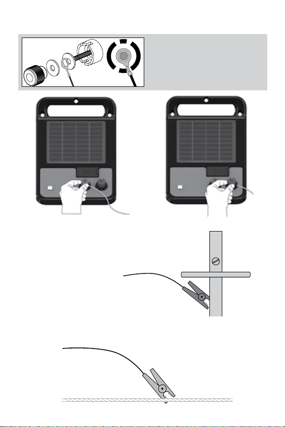
1) Make sure your 2G SIM card is registered with the phone network.
2) Insert the SIM card into the Fence Monitor.
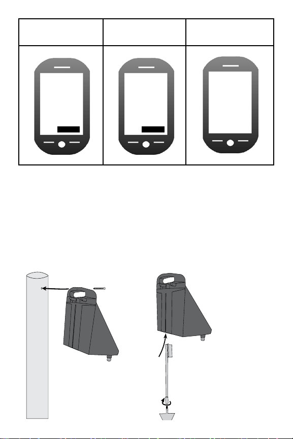
3) Turn on the Monitor, place in the sun and wait for the status light
to flash green (allow up to 45 minutes for the internal emergency
battery to charge)
4) Once the SIM is activated, create a new contact in your mobile
phone for the Fence Monitor mobile phone number.
5) Text the word REG to the Fence Monitor. Wait for a response.
6) To test the unit, wait 5 minutes then turn off the fence energiser. An
SMS (Text) warning message should be issued by the Fence Monitor.
To register your warranty go to: www.wsregisteraproduct.net
Schnellstartanleitung. (Deutschland)
Befolgen Sie diese Schritte, damit der Fence-Monitor akkurat arbeiten
kann
1) Stellen Sie sicher, dass die 2G SIM Karte mit dem Telefonnetz
registriert ist.
2) Setzen Sie die SIM Karte in den Fence-Monitor .
3) Schalten Sie den Fence-Monitor ein, stellen sie ihn in die Sonne und
warten sie, bis die LED leuchte, grün blickt (erlauben Sie bis zu 45
Minuten das sich der internen Notfall Akku aufladen kann)
4) Sobald die SIM karte aktiviert ist, erstellen Sie einen neuen Kontakt in
Ihrem Handy für die Fence Monitor nummer.
5 ) Schicken Sie eine SMS mit ‘REG‘ an den Fence Monitor und warten
sie auf eine Antwort.
6) Um das Gerät zu testen, warten Sie 5 Minuten und schalten Sie das
Weidezaungerät aus. Eine SMS Warnmeldung sollte durch den Zaun
Monitor abgegeben werden.
Um die vollständige Gebrauchsanweisung herunterladen zuladen gehen
sie bitte unter, www.wsregisteraproduct.net/4.html