Rutus Argo NE User manual


Dear User!
Thank you for purchasing this product.
This detector has been designed with the latest technology to allow you to make
the most of your passion, to discover the remains of the past.
Argo NE is a continuation and development of the concept of two detectors
that have gained popularity among the searchers, Argo and Optima.
Both detectors are relatively simple to use, encouraging users to begin working from
the first moment but at the same time are very effective, deep and powerful detectors.
We hope that during your adventures our latest product meets all of your expectations.
This manual will give you all the necessary information, so that you can quickly
understand how the Argo NE works before going into the field.
Please remember that while you are searching, you will be uncovering history.
Do not destroy these unique remains in the process, take some time to get
to know the law of your country and leave your search area clean and tidy.
Be an exemplary user of Argo NE:
Do not use the detector in areas that are under archaeological protection
or where an archaeological dig has been conducted.
Before entering private property, ask the owner for permission.
Do not make life harder for farmers or foresters by damaging crops or disturbing animals.
Do not leave a mess after yourself. Leave the place you have searched,
in the same condition as when you arrived.
Refill all holes, take any rubbish with you and put it in
the next rubbish bin you come across.

TABLE OF CONTENTS
DETECTOR ASSEMBLY...............................................................................................................3
BATTERY INSTALLATION............................................................................................................3
CONTROL PANEL.........................................................................................................................4
TURNING ON/OFF........................................................................................................................4
GROUND BALANCE.....................................................................................................................4
DISPLAY........................................................................................................................................5
OPERATING MODE SELECTION................................................................................................6
IDENTIFICATION..........................................................................................................................6
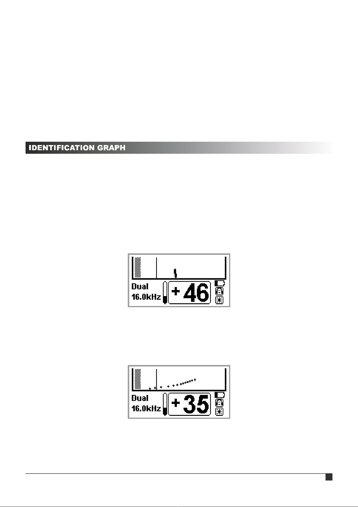
IDENTIFICATION GRAPH............................................................................................................7
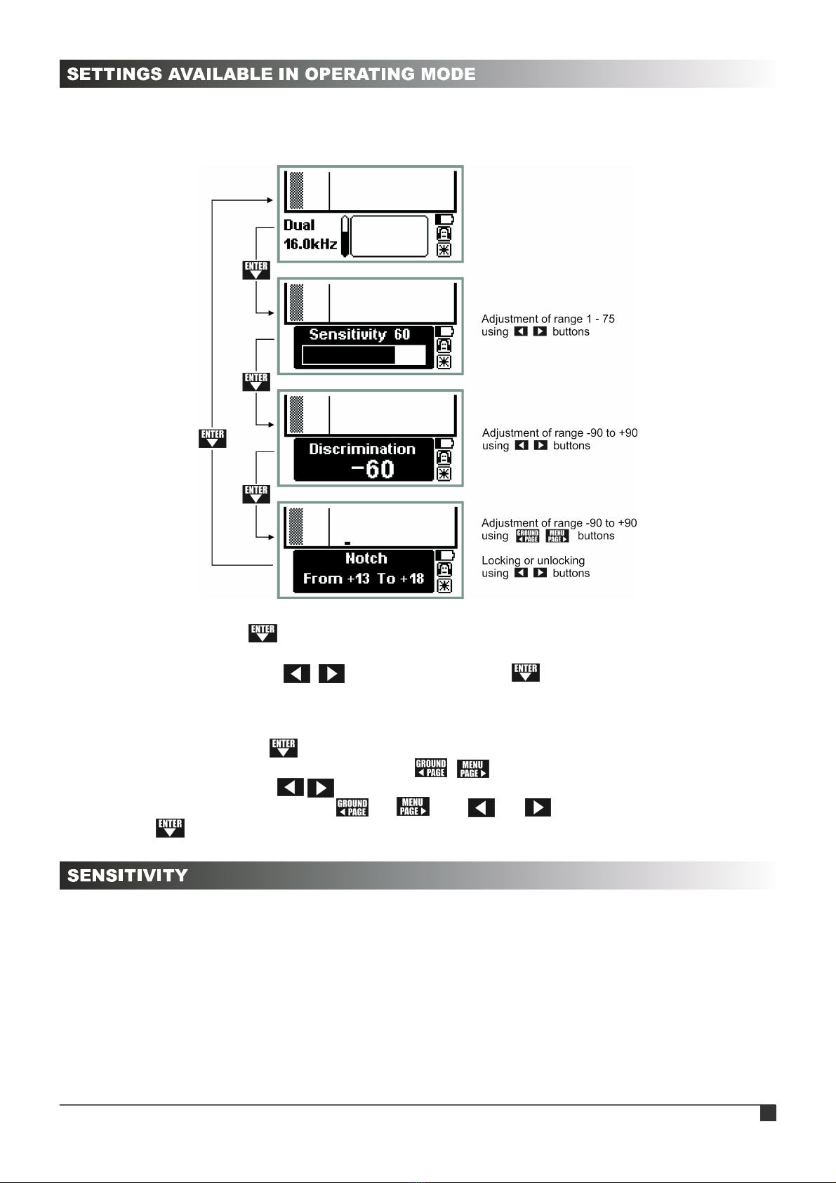
SETTINGS AVAILABLE IN OPERATING MODE...........................................................................8
SENSITIVITY.................................................................................................................................8
DISCRIMINATION.........................................................................................................................9
NOTCH..........................................................................................................................................9
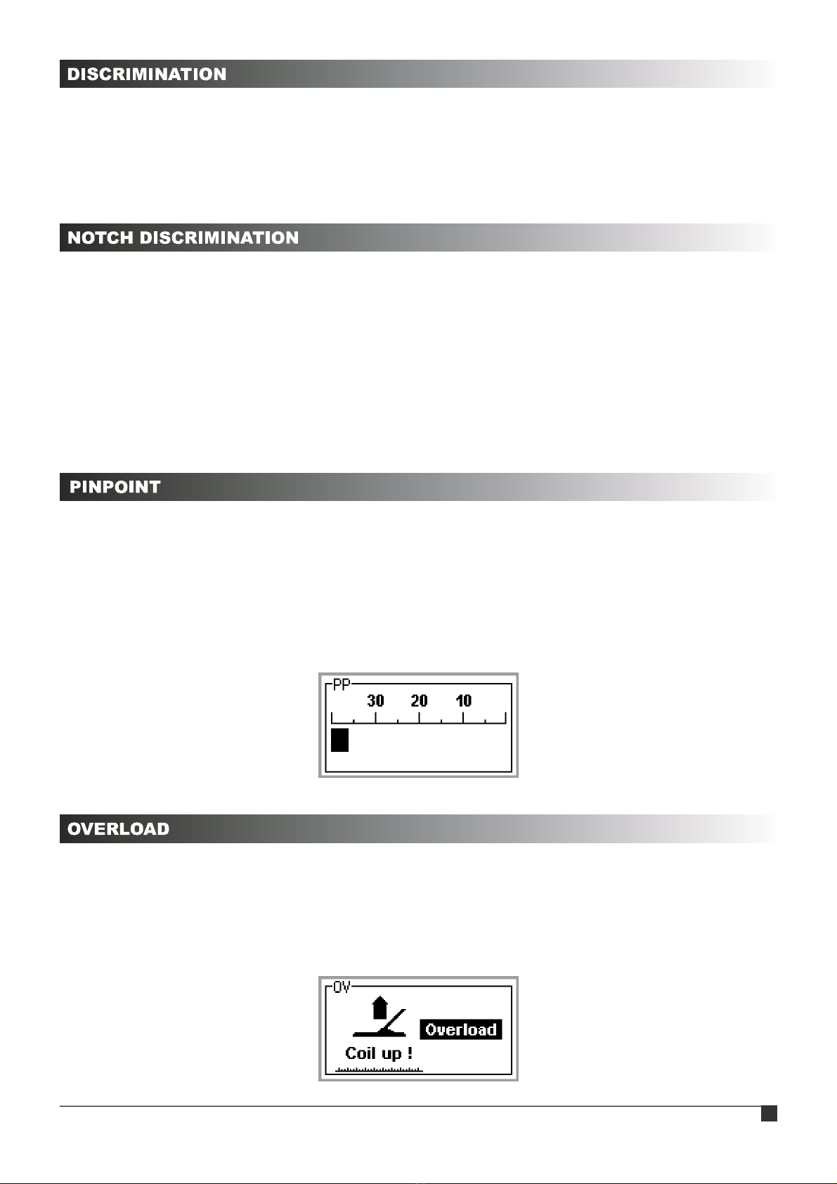
PINPOINT......................................................................................................................................9
OVERLOAD...................................................................................................................................9
MENU LAYOUT...........................................................................................................................10
MAIN SETTINGS.........................................................................................................................11
Frequency..........................................................................................................................11
Frequency shift..................................................................................................................11
Hot Rock............................................................................................................................11
Backlight............................................................................................................................12
Volume...............................................................................................................................12
Wireless.............................................................................................................................12
Language...........................................................................................................................12
MOTION MODE SETTINGS.......................................................................................................13
Th Level.............................................................................................................................13
Th Tone..............................................................................................................................13
Tones.................................................................................................................................13
Audio Gain........................................................................................................................14
Masking.............................................................................................................................14
Reaction............................................................................................................................14
NON-MOTION MODE SETTINGS..............................................................................................14
Th Level............................................................................................................................15
Th Tone.............................................................................................................................15
VCO..................................................................................................................................15
SAT...................................................................................................................................15
DUAL MODE SETTINGS............................................................................................................15
DETECTOR'S CAPABILITIES.....................................................................................................16
MODES OF OPERATION...........................................................................................................17
MODES OF OPERATION AND SEARCHING.............................................................................19
SEARCHING – USEFUL ADVICE...............................................................................................19
NOTES FOR MAINTENANCE....................................................................................................20
EU DECLARATION OF CONFORMITY.......................................................................................21
RUTUS Argo NE

The detector assembly is simple and requires no tools, a properly assembled
detector is shown on the front cover of the user’s manual. Before assembling the
stems, make sure the clamp is unlocked by rotating it as shown in the picture. Next
push the spring buttons in and insert one stem into the other. Release the buttons
and they will lock in the holes. Next secure the clamp by turning it the other way until
it is hand tight. Do not over tighten the clamps or the screw securing the search coil.
The connecting cable should be secured with two rubber cable tie to the base of the
lower stem, and then wrapped around the stems. Doing this will prevent from creating loose loops of the
cable in the search coil area and protect the cable from pulling out from the search coil. The third rubber
cable tie should be used to attach the cable to the top of the detector, which will prevent the cable from
slipping downwards. Be careful not to pull the cable too tight when inserting the plug into the
socket - as this may damage the cable. See the photo on the front page for best practice. The armrest
is adjustable – first remove the screw, then move the armrest to the desired position and re-tighten the
screw.
NOTE: Try to avoid creating large loops of cable near the edges of the search coil, as this may result in
the detector giving false readings.
NOTE: When disassembling the detector, begin by unplugging the search coil from the socket and
loosen the cable wound around the stems. Once this is completed the rest of the detector may be
disassembled into its basic components. Finish by loosening the screw securing the search coil and fold
it together with the stem.
NOTE: The coil cable plug is protected by a silicon cover. This is there to prevent dirt and sand from
damaging the delicate, gold connector pins. If the plug is not in the socket, it should always have the
protective cover on.
NOTE: Cleaning the detector must be done using only water with soap on a damp sponge.
Do not use any solvents or petroleum products. Regularly clean the stems and clamps.
Use good quality alkaline or rechargeable batteries of well known brands. Do not mix new and
discharged batteries or regular ones with rechargeable ones. Used batteries must be removed from the
detector as soon as possible. Remember to remove the batteries from the detector if it is not going to be
used for an extended period of time. The warranty does not cover damage caused by leaking batteries
damaging the electronics.
In order to install the batteries, press the centre of the lid (2), unlock the clip
(1), and then remove the lid (2) as shown on the picture. After pulling out the battery
holder, insert the batteries as shown on the holder, remembering to check if the
polarity is correct. It is important to make sure that the spring is pressing the batteries
tightly. The holder can only be inserted into the detector one way – the shape
prevents it from being inserted the other way around.
NOTE: The detector has a battery indicator which monitors the batteries charge level. As the batteries
lose charge, the indicator bar will shorten. When the batteries need replacing the detector will turn off
automatically. It is not possible to turn on the detector if the batteries charge is
too low. As the battery reaches this level, the detector will make a sound of
decreasing frequency and the display will show a symbol of a crossed out
battery (see picture beside). The circuit monitoring the battery level shows
a charging level of 1.5 V for standard alkaline batteries. When using 1.2 V
rechargeable batteries the battery charge icon will never be full.
RUTUS Argo NE 3

The picture below shows the functions of individual buttons on the control panel.
The detector is turned on by pressing the button with the power icon. The detector can
be turned off only from the operation mode by holding the button for 1 second. In the
menu the button is used only to enter the tones editing screen. A short press of the button in
the operation mode does not turn the detector off but changes to the operation mode selection
screen.
After turning the detector on, the ground balance procedure must be completed. This can
be done at any time by pressing the button. When the message « Put search coil UP Then
pull trigger » is shown, the search coil should be lifted at least 0.5 m above the ground, and then
the trigger should be pulled. The display will then show the « Preparing Data » message, this
means that the processor is collecting the data necessary for operation. After this process ends
the « OK » message will appear followed by the main screen of ground balance (see picture
below).
Correct ground balance is gained by „pumping”. The search coil
should be slowly moved up and down above the ground, each cycle
taking about a second. The detector will display the number of cycles
remaining – decreasing from 5 to 1 and after the last movement up the
message « Detector ready, pull trigger » will be shown. After pulling the
trigger, the soil phase reading will be gathered and after about 2 seconds the detector will be
ready for searching.
RUTUS Argo NE 4

Most soil types gives a phase reading of around -87.0. Wetlands can produce higher
phase readings (e.g. -83.0). On soils with high conductivity (where the phase readings are
significantly more than -87), working at high sensitivity may be difficult – the sensitivity in this
case should be reduced. Should the ground balance results be noticeably higher than these
values (e.g. -75.0), there is a high probability that some metal objects are present in the balance
area. The ground balance should be repeated again at a different location a few metres away.
NOTE: If you wish to use the detector with the factory presets, pull the trigger after the main
ground balance screen is displayed. This is very useful if you want to find a clean place quickly,
so that you can perform the ground balance process correctly using the „pumping” technique.
A single ground balance process does not guarantee stable operation across an entire
search area or for the whole of a day's searching. It is best to repeat a ground balance process
each time a new area is started or when the detector starts to give false readings. Examples of
new areas would be where field changes to forest, or when moving from a track to wetlands.
The detector will also require a ground balance check when either the program, the
frequency or the hot rock parameters are changed.
NOTE: While data is being prepared for work (« Preparing Data » screen) the search coil must
be raised a minimum of 0.5 m above the ground and away from metal objects. Ground balance
must be done at least 15 m away from other detectors. Not following these guidelines will not
damage the detector, but it will cause the detector to operate less accurately – a proper ground
balance procedure will fix this quickly.
The picture below shows the display in the operation mode.
RUTUS Argo NE 5

The detector has three operating modes: Motion, Non-motion and Dual mode. For
a detailed description of these modes, see page 17.
Each operating mode can be modified to your own requirements, just enter the menu and
change the settings shown. Modifications are stored after the power is switched off (however
not when the battery pack is removed while the detector is on, which is inappropriate). If the
changes are not what you expected, then they can be reset using the factory settings.
NOTE: The factory settings for each operating mode are optimised for ease of use. When
beginning to use the detector we strongly recommend trying the detector with these factory
programs without changing settings in the menu. This will help you to learn quicker how the
detector operates.
Turning the required operating mode on is done by pressing the button in the
detector’s operating mode. The operation mode selection screen will appear:
The buttons are used to select the operating mode you would like, then press
the trigger to enter the program. After changing the operating mode a ground balance needs to
be done, and the detector will guide you through this process.
If you want to reset a given operating mode to the factory specifications, bring up the
operation mode selection screen (by pressing the button) and use the button to go down
to the « Reset » option, then use the button to choose « Yes ». Use the trigger to leave the
operating mode selection screen, the reset confirmation screen will then appear (« Really? »).
Use the button to select « Yes ». Use the trigger to complete, the settings for the chosen
operating mode will then be reset. Resetting the chosen mode of operation to the factory
settings does not result in resetting the main settings or the sound programs.
Argo NE is a detector which has a built-in metal object identification circuit. The detector
has 180 identification points which can be set within the range -90 to +90. It analyses the signal
from a metal object several hundred times per second, after each identification process, the
internal memory of the device saves a specific digital value. The values stored in the memory
are used to calculate an average identification value and an identification graph is shown. The
average value depends on the characteristics of the object that is below the search coil.
There is a common misconception among searchers about identification. Unfortunately,
the dependency between object type and the value of the identification is complex. The basis for
understanding these dependencies and extracting valid conclusions is the following: "If the
magnetic properties of an object are greater than the conductive, then the identification number
will be negative, otherwise the identification number will be positive."
RUTUS Argo NE 6

Negative identification numbers are assigned to objects made of ferromagnetic materials
such as iron, steel and nickel. Unfortunately, if these objects are made in the form of sheets –
i.e. they have a small thickness but a large surface, the vortex currents that can be created on
the surface of the object without difficulty will dominate over the magnetic properties. In the case
of ferromagnetic objects their position relative to the search coil strongly affects the identification
- the steel plate in a flat position will be identified in the positive range (because the vortex
currents will have an advantage over its magnetic properties), but the same plate in a vertical
position will be identified in the negative range (the vortex currents are not inducted, but the
magnetic field lines are strongly deflected.)
In the case of objects of non-ferrous metals, the dependencies are simpler: the larger the
object, the heavier the object and the better the conductor - the higher the value.
The identification graph is a graphical representation of the data collected by the
identification circuit while moving the search coil over an object and is stored in the device’s
memory. This feature is unique to this detector, and allows for quicker identification of ferrous
objects than any other method.
If the graph closely resembles a straight or inclined line then an object's composition is
very likely to be of a single material and the digital identification has a high probability of being
correct (a straight line in the range of iron is iron, a straight line in the range of non-ferrous
metals is most probably a non-ferrous metal).
When the graph is clearly bent, curved or spread across the whole of the display, it is
highly probable that you are dealing with an object such as a can, a thin steel sheet or other
steel object whose magnetic properties are lesser than its conductive properties.
RUTUS Argo NE 7

Adjusting the Sensitivity level, Discrimination or access to the Notch function is done
straight from the detector’s operating mode. The way to access the settings is described below.
After pressing the button the « Sensitivity » message will appear on the display,
a number describing the Sensitivity level and a linear scale showing the adjustment range. The
adjustment is done using the buttons. Pushing the button a second time will show
the Discrimination level. Adjusting the Discrimination is done in the same way as adjusting the
Sensitivity.
Another press of the button will lead to the Notch function. The Notch point, which
we want to lock (or unlock) is chosen using the buttons. The chosen Notch point is
locked or unlocked using the buttons. To quickly block or unblock a larger range of
points, the user can use the buttons: or and or simultaneously. After
pressing the button the screen returns to the operation mode screen.
Sensitivity in the Argo NE detector may be adjusted across 75 levels. The Sensitivity level
set by the user determines the detector's range and more importantly it's stable operation. In
areas which are littered, freshly ploughed or have heavy electromagnetic interference, operating
with maximum Sensitivity is not possible. Sensitivity has to be adjusted in accordance to the
terrain where the search is being conducted and using your own experience. New users should
begin their searches with the detector set to Sensitivity levels between 40 and 50.
RUTUS Argo NE 8

Discrimination is a function which enables the removal of sound signals from unwanted
objects, which have a identification number lower than the set discrimination value.
E.g. a discrimination value set to -20 will result in a lack of the detector’s reaction to most small
steel objects. The discrimination value can be set within the range -90 to +90.
The detector has 20 points of Notch function. Each of which can be locked individually.
This function is used to eliminate signals from objects within a narrow range of identification
point, which helps to search in places where there is a large amount of similar, unwanted
objects. For example, to eliminate signals from spent cartridges littering a battlefield but not
eliminating signals from other objects.
When using Notch it is important to remember that other objects with characteristics
similar to the „unwanted” ones will also be eliminated. For best results, only use this function in
exceptional circumstances.
This function allows for the quick and easy location of an object. To use the pinpoint
function move the search coil away from the area where the object is and then press and hold
the trigger. To pinpoint the object make a cross like movement, to find the point where the signal
is the strongest. The depth of the object shown on the screen is set-up for medium-sized
objects. This means that for large objects the depth will be larger than indicated on the screen.
The operation of the indicator and depth gauge is not dependent on the sensitivity of the
detector, however the sound signal is.
An overload means that the signal from an object is too strong for the detector to process
correctly. Thankfully this does not mean the detector has been damaged. An overload is
indicated by a rattling sound and the « Overload » message on the display. In this situation lift
the search coil up – when the overload message has gone, the display will show the
identification value for the object.
RUTUS Argo NE 9

The menu is divided into two pages: Main settings and current mode of operation
settings. To enter the Menu press the button, and then press the trigger to leave. To switch
between pages press the button and then switch between the settings on each individual
page by pressing the button. In the pictures are the factory value for each of settings. Main
settings can not be reset back to the factory settings.
MAIN MOTION MODE NON-MOTION MODE DUAL MODE
SETTINGS SETTINGS SETTINGS SETTINGS
RUTUS Argo NE 10

No matter what mode of operation we use the detector, there are settings which are
common to all operating modes of the detector.
Setting Adjustment range
Frequency 6.6 kHz, 16 kHz
Frequency shift -2 to +2
Hot Rock -30 to +30
Backlight 0 – 29
Volume 1 – 30
Wireless Off, Ch 1, Ch 2
Language Polski, English, Deutsch, Cestina *
* The manufacturer reserves the right to add
additional menu languages without notice
Frequency
The user has two operating frequencies: 6.6 kHz and 16 kHz. The higher frequency is
designed to search for very fine, thin objects such as jewelry and very fine coins. Iron masking
at 16 kHz is low. The 6.6 kHz frequency is a universal frequency - it can be used if the purpose
of the search is not for small items.
NOTE: After each Frequency change the detector requires the ground balance procedure to be
repeated.
Frequency shift
The Frequency shift gives you the ability to slightly separate the detector's operating
frequency to compensate for electromagnetic interference - for example when another metal
detector is operating nearby.
NOTE: After each Frequency shift change the detector requires the ground balance procedure
to be repeated.
Hot rock
This adjustment allows the detector’s reaction to magnetic rocks and objects of
particularly high identification value to be modified. Magnetic rocks are plain field rocks which
have residual magnetic properties. Magnets do not attract them, but they influence the
detector’s operation. They are essentially recognized by the detector as signals with an ID value
of -90 and in most cases these objects can be isolated using the discrimination option, in the
same way as simple steel scrap. Objects with exceptionally high ID values (+89 or +90) are
large pieces of aluminium, aluminium sheets and aluminium canteens. In this way Hot rock
adjustment can be used to set the reaction to objects at both ends of the identification scale.
This is a result of the detector „virtually” connecting both ends of the scale. The microprocessor
does not treat the identification scale as linear, but rather circular, where values of -90 and +90
are connected, and therefore an object identified as above -90 is automatically identified as a
high value object and vice versa.
RUTUS Argo NE 11

Hot rock adjustment is simply a slight tuning of the circular scale on which the detector’s
operation is based. In this way magnetic rocks can be set apart from the -90 value and will be
more clearly be discriminated (but equally the aluminium canteens will fall into the -90 value and
thus are also discriminated). It is equally possible to adjust the values in the other direction:
moving the large aluminium objects to lower identification values (e.g. +88) and in this way
increase the effectiveness of detecting these kind of objects but this may result in magnetic
rocks giving a high, fuzzy tone. The factory setting for magnetic rocks correction is set to Neutral
and this is the best setting for 99% of search areas. But if for some reason there is a need to
increase the masking of magnetic rocks, use the button to set it to negative values.
The adjustment of values into the positive range will increase the detection range for canteen in
the Motion mode.
NOTE: After each change to the Hot rock adjustment the detector requires the ground balance
procedure to be repeated.
Backlight
Adjustment of the display’s backlight. This allows searching in low light conditions. If the
backlight setting is 0, then when entering the menu the backlight will automatically switch on.
The backlight will switch off by leaving the menu screen.
Volume
To adjust the volume of the sound received from objects. The level of the Threshold is not
dependent on this setting.
Wireless
Argo NE has a built-in wireless digital data transmitter which can work on one of two
available radio frequencies. The design of the digital connection was made especially for our
detectors – therefore there is no lag or background noise. The use of the accompanying
wireless devices is detailed in their respective user’s manuals.
Off The transmitter is off, the built-in speaker and headphone’s socket are active
Ch 1, Ch 2 The transmitter is on, the detector’s sound generating circuit is off
Language
Allows the menu language to be chosen.
RUTUS Argo NE 12

Setting Adjustment range
Th Level 0 – 100
Th Tone 60 – 500 Hz
Tones 1, 5, Pr 1, Pr 2, Pr 3
Audio Gain 1 – 20
Masking 0 – 6
Reaction 1 – 3
Th Level
The Threshold is the background sound which is always heard while the detector is
active. It can be increased or decreased depending on the user’s preferences and the level of
noise at the search site. The level of the Threshold should be set so that it is only slightly
audible – in this way you can be sure that you will hear even the quietest signals from objects.
Th Level and Th Tone adjustments can be made in the menu at the same time as listening to
the effects of these changes.
Th Tone
The Threshold Tone should be set as you wish – each user will have their own
preferences as to the sound frequency which is the most appropriate.
Tones
The detector has the ability to change the quantity of the tones signaling detection of an
object. If you select 1 tone, the item is simply signaled by the increase in the volume of the
Threshold. If you select 5 tones then the signaling method is as follows:
ID Range Tone
-90 – 0 131 Hz
1 – 12 262 Hz
13 – 30 523 Hz
31 – 72 659 Hz
73 – 90 932 Hz
The user also has 3 custom sound programs. If any audio program is selected, there is
the option of programming any tone for the 20 identification sub-ranges (5 for the range from
-90 to 0 and 15 for the range 0 to +90).
Programming is as follows:
Select Program (Pr 1 or Pr 2 or Pr 3) in the menu, then press the button. This transfers to the
edit screen of the sound program. The buttons are used to choose the ID range for
which a specific tone is applied and the buttons are used to change the frequency of
the sound. Once all the required sounds have been determined from the edit screen, exit with
the trigger.These programs are common to Motion and Dual mode work.
RUTUS Argo NE 13

Audio Gain
The Audio Gain adjustment changes how detected objects are signalled. A small Audio
Gain will mean that weak signals from the Motion channel will have a quiet sound and strong
signals, a loud sound. This provides „depth” in the form of sound, which allows us to hear how
far from the search coil an object is located. If you set the Audio Gain to the maximum value
then all signals will produce a tone of maximum loudness.
Masking
This setting is used to adjust the masking of short signals in the detector’s speaker.
These signals come from the partially discriminated signals of bottle caps, iron, magnetic rocks,
junk etc. Masking improves the quality of discrimination. For a zero Masking value, the detector
will give produce a tone for all signals, even the shortest ones. Some small steel junk will be
hard to discriminate, the detector will be „noisy” during a search.
As the Masking value increases the operation of the detector becomes less “noisy” and it
becomes possible to search for non-ferrous metal objects amongst iron junk. Some may
assume that Masking should always be set to the highest value, but this is not the case – high
Masking settings can cause a lack of signal for objects on the borders of the range. In clear
terrain, if the user wants to reach as deep as possible, the Masking value should be set as low
as possible.
For Reaction set to 3 (fast), the maximum Masking value is "4". The detector software
automatically adjusts the Masking setting when the user sets a higher value.
Reaction
This adjustment gives the ability to select the speed of soil filtering. It is an essential
factor in the ability to detect large, deeply placed objects, the speed of detection and its
resistance to soil mineral contents.
Filter 1 Filter for searching "relics" that is large objects at large depths. Not recommended
in standard searches. Low resistant to soil mineralization.
Filter 2 Standard filter for most searches. Resistant to soil mineralization, perfect for coins
and other objects.
Filter 3 Only for use when searching for small objects of non-ferrous metals in rubbish
and in areas of very high mineralization.
Setting Adjustment range
Th Level 0 – 100
Th Sens 60 – 500 Hz
VCO Yes, No
Th SAT 0 – 20
RUTUS Argo NE 14

Th Level
During the search in Non-Motion mode, the Threshold should be set to a level that
ensures audibility. This ensures that the detector is working properly and its range is maximized.
Th Sens
As in the Motion mode - the tone of the Threshold is chosen so that the user does not
become distracted.
VCO
VCO is a function that allows the pitch of the All metal channel to smoothly change
depending on the signal strength. Human hearing perfectly distinguishes even slight changes in
sound frequencies – as a result, an experienced searcher is able to recognize the size and
depth of the object, and in many cases can recognize their mutual position. We strongly
recommend using the VCO from the very start of your experience with the detector.
Th SAT
The Th SAT function reduces the effects of external conditions on the operation of the All
metal channel of the detector. To put it simply: by using this setting we can prevent the detector
mistuning in the sun. Another important function of SAT is changing the response of the All
metal channel. For high SAT settings (especially SAT = 20) the user has the ability to audibly
differentiate between a large number of small objects laying at a shallow depth from one big
object. A setting of 0 means that the Th SAT circuit is completely turned off – detector is fully
non-motion. With this SAT setting, care must be taken to ensure proper and frequent Ground
balance because the detector will signal each change in soil mineralization, especially at the
transition from e.g. forest to field, as well as under the roots of large trees or near animal dens.
Less skilled users can overcome this by using higher SAT values. When set to 20, the SAT
function is maximally fast.
NOTE: Turning the Th SAT circuit on can result in a decrease in the range of the detector’s All
metal channel. The amount of range loss will depend on the speed at which the search coil is
moved.
Setting Adjustment range
Th Level 0 – 100
Th Tone 60 – 500
VCO Yes, No
Th SAT 0 – 20
Tones 1, 5, Pr 1, Pr 2, Pr 3
Reaction 1 – 3
Masking 0 – 6
In the Dual mode, settings similar to Motion and Non-Motion mode settings are available.
They have the same meaning and action. In the Dual mode, the Audio gain is not set - this
parameter is held steady at the optimum level.
RUTUS Argo NE 15

To understand how Argo NE works and it's potential, the device’s flow chart below will
help:
Argo NE consists of several basic functional blocks: a transmitter, a search coil, a Motion
channel, an All metal channel, a sound control circuit and parts used to communicate with
a user: a display and a speaker.
The transmitter controls the transmitting coil in the search coil and the user may choose
between one of two frequencies: 6.6 kHz or 16 kHz. The signal from the search coil’s receiving
coil (after processing, not taken into consideration in the chart above) is directed simultaneously
through two channels:
1. Motion channel with object identification and discrimination
2. All metal channel with adjustable operation speed
Signals processed in both channels are directed to the sound control circuit.
The Motion channel with object identification and discrimination ensures the objects are
properly identified. The identification result is directed to the display independently of the sound
control circuit, but the sound signal is directed to the sound control circuit only when it is allowed
by the discrimination, Notch or Masking settings. The Motion channel – as its name suggests –
requires that the search coil be moved relatively to the object.
The All metal channel reacts to all metal objects or, depending on the soil category (using
data from ground balance) and SAT setting, can react to magnetic objects under certain
conditions (so called hot rocks, ceramics, bricks etc. and objects other than the soil).
The All metal channel can be completely non-motion (SAT = 0) or it may require the
movement of the search coil as the SAT parameter is increased. When SAT is set to 20, the All
metal channel works as a „single-filter” Motion channel – where movement is required.
RUTUS Argo NE 16

This design allows the detector to work in three modes of operation:
1. Motion mode with discrimination – a classical detector.
2. All metal Non-motion mode with different speeds – a mode used to search for large objects.
3. Dual mode – Motion mode with discrimination + All metal with any speed setting.
An important part of operating the detector is to understand the characteristics of the
basic modes of operation.
1. Motion mode with discrimination
In this mode the movement of the search coil relative to the metal object is necessary,
both identification and discrimination work in this mode.
Discrimination
This is the ability to block sound signals for objects with conductivity (ID) lower than the
set value. The discrimination scale starts with iron and goes through foil, gold and ends with
silver. A discrimination level set to 0 allows searches without detecting ferrous objects. Naturally,
there will be times when the detector will signal the presence of large ferrous objects as „non-
ferrous” objects. It is generally recognized that discrimination works best for small objects at
shallow depths.
Notch
This type of discrimination allows for selective operation – the user can choose which
types of objects will be indicated and which will not be.
Identification
This function is described on page 6. In practice it allows for the non-standard use of the
motion operation – by setting the discrimination to -90 and not using Notch. The detector will
use sound to signal all metal objects, on the basis of the sound and the indications on the
display, the user will be able to recognize all the objects in the soil. In this way the user is aware
of the conditions in which they are performing the search. If using discrimination in the Motion
mode, they may not have a full view of the situation and would not be aware of how many metal
objects are littering an area.
2. All metal Non-motion
The All metal channel has a variable speed and, depending on the SAT setting, we can
have a fully non-motion (SAT = 0) or fully motion (SAT = 20) working detector.
Fully Non-Motion mode
This operating mode doesn’t need the search coil to be moved to create a sound signal.
It works when SAT are set to 0. The detector signals all metal objects using the sound channel.
The volume and the tone of the sound, depends on the signal’s strength – this gives the user
information about the object’s size and distance from the search coil.
RUTUS Argo NE 17

When using a detector which has been well ground balanced, and by using the Th Level
setting at 0 a sound signal will be received from a metal object. The only way of identifying an
object is by checking the information shown on the display. The key characteristic of this
mode is that it provides the maximum detection range for all metal objects in the ground.
NOTE: In this operating mode it is important to reset the All metal channel, this needs to be
done away from metal objects. For best operation in Non-motion mode, listen to the Threshold,
this should be set so that it can be heard. If the Threshold becomes inaudible then a reset is
required, equally if the detector suddenly starts creating a loud sound with no apparent reason,
then reset the channel.
NOTE: In the Non-Motion mode the object ID information is sent from the Motion channel so
that the search coil motion is required for the information to appear on the screen.
All metal Motion
A mode of work which enables searching for large objects but with the ability to
separately identifying many small objects in the ground. This is All metal mode, where
movement of the search coil is required. Works with SAT setting above 0.
The detector uses sound to signal all metal objects. When the search coil is stopped in
close proximity to a metal object, the detector will automatically „tune” itself to the metal and
stop signaling the object. How long this takes will depend on the SAT value: if SAT is set to 1
then this will be 1 second, if SAT is set to 20 – it will be approximately 0.7 seconds.
Under certain conditions, and depending on the ground balance, the detector may react
to non-metallic objects. Hot rocks and other objects which have properties which are not similar
to soil, may create a sound signal. An experienced user will have no problem differentiating
these signals from normal signals as they have very different characteristics. The only way to
identify the conductivity of these metals is to check the ID readouts on the display. The All metal
Motion mode has greater range than the Motion mode with discrimination.
NOTE: When listening to deeply placed objects it is a common mistake to swing the search coil
too quickly over an object. After the search coil passes over an object and emits a sound, the
Threshold will be turned down. To confirm an object has been located it is important to wait for
the Threshold to return to its original level. This time can be shortened by resetting the All metal
channel using the trigger.
3. Dual mode
This mode combines the Motion mode with discrimination and the All metal mode. This
combination provides the advantages of both modes – identification coming from the Motion
channel and the maximum range of the All metal channel. To better understand the
characteristics of the Dual mode it is best to get to know the following modes first: Motion with
discrimination and All metal Non-motion with different speeds.
RUTUS Argo NE 18

When beginning to decide which mode to use for searching, it is best to follow a few
simple rules. These are only initial rules as those with a little more experience will be able to
select the most appropriate for particular situations and object types.
Typical use of operation modes:
1. To search for small objects in fields, the optimal modes will be the Motion ones (with
discrimination and All metal). The correct mode will depend on the user’s expectations, if the
user wants to search only for clear signals from non-ferrous metal objects, Motion with
discrimination is best. If the user wishes to find all kinds of small objects, All metal Motion mode
will be better.
2. To search for large objects at depth, the Non-motion mode is the best.
3. For universal searches the Dual mode will be the best.
Incorrect modes:
1. Non-motion mode will be very poor when searching for small objects in highly littered area.
2. Motion mode with discrimination (especially for Reaction set to 2 and 3) will not give good
results when searching for very large, deeply located objects or to conduct search in places
where the movement of the search coil is impossible e.g. very dense bushes, or holes.
As your knowledge of the particular characteristics of this detector increases it will
become easier to choose the best mode for each terrain and searching task.
Searching is done by sweeping the search coil left and right as quickly as is comfortable
and as close to the ground as possible. The exception to this rule is when searching for large
objects using the Reaction set to 1 – in this case it is best to keep the search coil 20 cm above
the ground. Touching the ground with the search coil should be avoided, try to avoid hitting it
against rocks and other objects protruding from the ground. While the search coil is designed to
be resistant to damage when hit against hard objects, a more effective search will be had if this
can be avoided.
The search coil should be held parallel to the ground, as this is very important to ensure
an effective search. This is especially important when reaching the end of each left and right
swinging motion, as lifting here changes the distance from the ground. This changes the level of
the soil signal, which results in the filters having to process this, giving a decrease in search
efficiency. Over time try to get into the habit of moving the search coil parallel to the ground.
How fast you are able to search depends on your ability to sweep, however sweeping too
fast can cause a drop in effectiveness also, especially in very littered terrain. In Motion mode
with discrimination, swinging the search coil too slowly will also decrease the effectiveness,
especially at the Recation set to 3. For these reasons sweeping should be no slower than 0.3
m/s and no faster than 1.5 m/s.
RUTUS Argo NE 19
Table of contents
Other Rutus Metal Detector manuals
Popular Metal Detector manuals by other brands

Compass
Compass Challenger X-100 instruction manual

Eriez
Eriez Metalarm HH-10 Installation, operation and maintenance instructions

Ceia
Ceia HI-PE multi-zone Series Installation, use and maintenance

Makro Detektor
Makro Detektor CF77 user guide

Garrett
Garrett GTI 2500 owner's manual

Mikron
Mikron Stinger 2 User's operating manual