RV Products BAL LoPro SJ24 User manual

CLASSIC MODELS: 24002C, 24002D, 24003D, 24009, 24010 & 24013
LoPro SJ24 MODELS: 24028 & 24008
FOR USE ON ALL RECREATIONAL VEHICLES
LEVELING SCISSORS JACKLEVELING SCISSORS JACK
IMPORTANT: READ THE FOLLOWING INFORMATION BEFORE OPERATING YOUR JACK!
WARNING!
THIS LEVELING SCISSORS JACK IS DESIGNED TO:
LEVEL AND STABILIZE THE FRONT AND REAR OF ALL RECREATIONAL VEHICLES BY REDUCING
THE AMOUNT OF SUSPENSION FREE-PLAY WHEN PARKED FOR CAMPING
• DO NOT ATTEMPT TO USE THIS SCISSORS JACK TO LIFT EXCESSIVE WEIGHT OR TIRES OFF THE GROUND -
VEHICLE FRAME AND DOOR JAMB DAMAGE MAY OCCUR. USE ONLY STOCK HANDLE SUPPLIED.
DO NOT USE A CHEATER BAR ON HANDLE.
• DO NOT ATTEMPT TO USE THIS SCISSORS JACK FOR ANY PURPOSE OTHER THAN ITS INTENDED DESIGN.
• DO NOT USE THIS SCISSORS JACK AS A TIRE CHANGING JACK.
WARNING: Do not use a cordless drill or cordless impact to operate the product unless the drill has
an adjustable chuck. If the product was supplied with a manual handle or ratchet, please use that to
operate the product. This allows you to feel the resistance during operation. A cordless drill or impact
will cause damage to the product unless the adjustable chuck is set appropriately. NEVER use a cordless
impact on an electric motor with a manual override.
CAUTION: Some RV’s may be designed and manufactured with sub-frames that are not capable of handling
additional force over and above the intended strength to support the cabin weight. Contact your RV manufacturer
for sub-frame strength information prior to using this Leveling Scissors Jack. NORCO CANNOT BE HELD RESPONSIBLE
FOR ANY DAMAGES DUE TO IMPROPER USE OF THIS PRODUCT. NORCO CANNOT BE HELD ACCOUNTABLE FOR THE
STRUCTURAL INTEGRITY OF ANY RV FRAME.
INSTALLATION AND OPERATING INSTRUCTIONS
RV PRODUCTS GROUP
®

PARTS LIST
Index No. Classic Series LoPro SJ24 Description Qty
1 P857022 P857095 Mounting Bracket 2
2
A
R857066 n/a 3/8-16 x 3" Hex Head Bol
t
2
2B N/A 501352 5/16-18 x .75" Hex Head Bol
t
4
3 P10011 N/A Upper Arm for 24" Jac
k
2
P857079 N/A Upper Arm for 30" Jac
k
2
N/A P857094 Upper Arm for LoPro SJ24 Jac
k
2
4 P857086 N/A Drive Screw for 24" Jack 1
P857049 N/A Drive Screw for 30" Jack 1
N/A P857096 Drive Screw for LoPro SJ24 1
5 857061 857097 Drive Trunnion 1
6 857064 N/A Plastic Spacer Bushing 2
7 P857024 N/A Lower Arm for 24" Jac
k
2
7 P857054 N/A Lower Arm for 30" Jac
k
2
7 N/A P857092 Lower Arm for LoPro SJ24 Jac
k
2
8 P857028 P857093 Base Pad 1
9 BAL1014 N/A 3/6-16 Nylon Locking Nut 4
9 N/A 851071 5/16-18 Nylon Locking Nut 8
10
A
R857065 N/A 3/8-16 x 2 3/4" Hex Head Bol
t
2
10B N/A R852781 5/16-18 x .75" Carriage Bolt 4
11 BAL2112 BAL2113 5/8 x 1 x 3/16" Washer 1
12 857060 857098 Stationary Trunnion 1
13 R857062 N/A Thrust Bearing (24010 & 24013) 1
BAL2111 /857038 N/A Thrust Washer Assy (24009) 1
N/A R857100 /R857100 Plastic Washer / Bronze Washer (24008) 1
14 R857076 R857077 Lock Pin 1
15 P857067 N/A Spacer/Bearing Washer 1
16 R857075 N/A O-Ring Brake 1
17 20037 N/A Crank Handle, Swivel Deluxe 3/4" 1
N/A 20036 Crank Handle, Fixed 3/4" 1
18 3152 3152 Mounting Screws 4

DETERMINING THE CORRECT MOUNTING LOCATION
TRAVEL TRAILER AND 5TH WHEEL
TRAILER MOUNTING PLACEMENT
STEP 1: PARK ON LEVEL GROUND
FRONT: Draw a string from the front corner of the
trailer frame to the bottom of the front tire (A).
REAR: Draw a string from the bottom of the back tire to
the back corner of the trailer frame (B).
NOTE: ANY OBJECT PROTRUDING BELOW THESE LINES CAN BE DAMAGED, DRAGGED OFF OR DESTROYED IN
UNEVEN TERRAIN, ENTERING OR EXITING DRIVEWAYS, DRIVING OFF READ, ETC.
MOTORHOME MOUNTING PLACEMENT
STEP 1: PARK ON LEVEL GROUND
FRONT: Draw a string from the motorhome front frame
extension behind the front bumper to the bottom of the
front tire (A).
REAR: Draw a string from the bottom of the back tire to
the back corner of the motorhome frame (B).
WHEN SELECTING PLACEMENT FOR INSTALLATION...
• Be sure that there is adequate ground clearance.
• Be sure that hex drive will be accessible.
• Be sure that scissors jack does not interfere or come into contact with any under chassis component.
BEFORE PROCEEDING TO INSTALLATION - PERFORM THIS IMPORTANT TEST
To insure clearance for the jack in the closed position, clamp the jack to the vehicle frame using two “C” clamps or Vise
Grips™. Close the jack with the crank handle and check to insure that the location chosen will allow the jack to close without
coming into contact with or obstruct any under chassis components (ie: plumbing, exhaust, etc.)
CAUTION: Some RV’s may be designed and manufactured with sub-frames that are not capable of handling
additional force over and above the intended strength to support the cabin weight. Contact your RV manufacturer
for sub-frame strength information prior to using this Leveling Scissors Jack. NORCO CANNOT BE HELD RESPONSIBLE
FOR ANY DAMAGES DUE TO IMPROPER USE OF THIS PRODUCT. NORCO CANNOT BE HELD ACCOUNTABLE FOR THE
STRUCTURAL INTEGRITY OF ANY RV FRAME.

INSTALLATION
OPERATION
STEP 1: Park RV on level ground. Prevent wheels from rolling by activating emergency brake and/or by using tire
chocks.
STEP 2: BEFORE PROCEEDING TO INSTALLATION - PERFORM THIS IMPORTANT TEST
To insure clearance for the jack in the closed position, clamp the jack to the vehicle frame using two “C” clamps or
Vise Grips™. Close the jack with the crank handle and check to insure that the location chosen will allow the jack to
close without coming into contact with or obstruct any under chassis components (ie: plumbing, exhaust, etc.)
- Open the jack until it touches the ground. Recheck location and adjust as needed.
- Once in place, apply enough pressure so jack cannot move during installation procedure. Remove clamps or Vise
Grips™.
BOLT-ON INSTALLATION
WARNING: BEFORE DRILLING HOLES, BE SURE THE DRILL
WILL NOT DAMAGE UNDER CHASSIS COMPONENTS
WHICH MAY BE ROUTED INSIDE VEHICLE FRAME (ie:
electrical, gas, water, generator fuel lines, holding tank
plumbing, water heater).
Refer to STEP 1 and STEP 2 above.
STEP 3: Using the mounting plate as a template, mark the
locations of the four mounting holes on the vehicle frame.
Remove the jack.
STEP 4: Mark the center of each hole location with a center
punch and hammer.
STEP 5: Drill a 1/8” pilot hole and nish by drilling holes
with a 5/16” diameter drill.
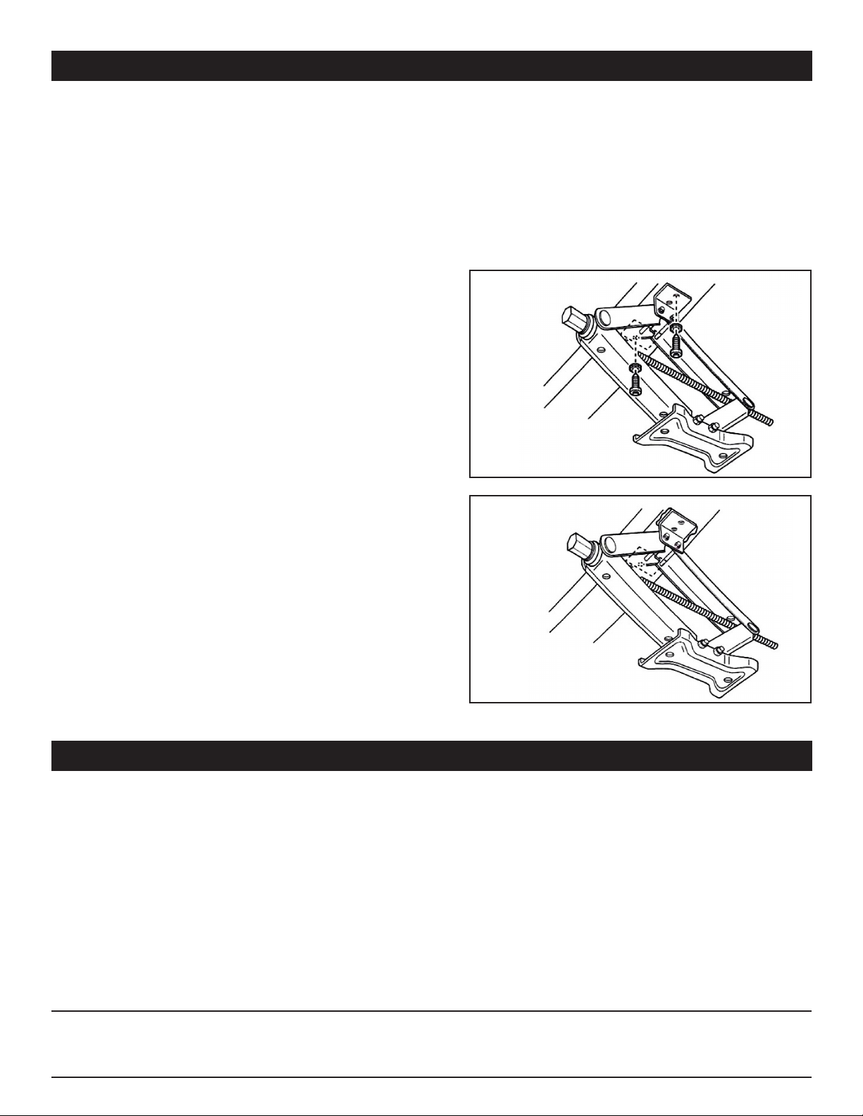
STEP 6: Reposition jack. Use a 9/16” socket and ratchet to
install the jacks to the vehicle frame using four screws and
four lock washers per jack (Figure 1).
WELD-ON INSTALLATION
Refer to STEP 1 and STEP 2 above.
STEP 3: Weld each mounting plate to the vehicle frame
with 4 each 1” welds, as shown (Figure 2).
STEP 1: Park RV on level ground, prevent wheels
from rolling, use tire chocks.
STEP 2: Level trailer fore and aft using tongue jack
or landing gear.
STEP 3: Check level gauge for low side of trailer,
crank down stabilizers on low side rst, bringing the
trailer to a ne level position.
STEP 4: Crank down stabilizers on opposite side of
trailer to insure maximum stability. Then re-snug
stabilizers on low side of trailer if necessary.
NOTE: BEFORE MOVING TRAILER: Crank up stabilizers
to fully closed position and tighten 1/4 turn to secure in
travel position (this prevents stabilizers from working open
due to road vibration).
MAINTENANCE: Use small amounts of WD-40 or similar
lubricant on drive screw threads and bolt locations as
required.
Figure 1
Figure 2
WARNING: DO NOT ATTEMPT TO USE THIS SCISSORS JACK TO LIFT EXCESSIVE WEIGHT OR TIRES OFF OF THE
GROUND - VEHICLE FRAME AND DOOR JAMB DAMAGE MAY OCCUR. USE ONLY STOCK HANDLE SUPPLIED.
DO NOT USE A CHEATER BAR ON HANDLE. DO NOT USE THIS SCISSORS JACK AS A TIRE CHANGING JACK.
This manual suits for next models
8
Table of contents