Ryobi PLT-2543 Instructions for use

N197

Fig. 1
Fig. 4
Fig. 2
Fig. 3
2
14
12
5
12
13
16
15
14
22
18
10
19
20
21
10
9
8
11
1
4
2
3
5
7
6

Fig. 7 Fig. 8
Fig. 9 Fig. 10
Fig. 5 Fig. 6
25
24
23
26
8
4
33
1
27
11
29
30
31
28

Fig. 13 Fig. 14
Fig. 15
Fig. 11 Fig. 12
35
34
38
32
3834
39
40
41
37
42
36
44
39
Fig. 16

Fig. 18
44
43
Fig. 17
1
28
17

- 1 -
WARNING
Do not attempt to operate this trimmer until you
have read thoroughly and understood completely
all instructions, safety rules etc contained in
this manual. Failure to comply may result in
accidents involving fire, electric shock or serious
personal injury. Save operator’s manual and
review frequently for continuing safe operation,
and instructing others who may use this tool.
READ ALL INSTRUCTIONS.
Replace string head if cracked, chipped, or damaged in
any way. Be sure the string head or blade is properly
installed and securely fastened. Failure to do so can
cause serious injury.
SPECIFIC SAFETY RULES FOR TRIMMER USE
GENERAL
SAFETY
SAFETY RULES
For safe operation, read and understand all instructions
before using the trimmer/brushcutter. Follow all safety
instructions. Failure to follow all safety instructions listed
below, can result in serious personal injury.
Do not allow children or untrained individuals to use this
unit.
Never start or run the engine in a closed or poorly
ventilated area; breathing exhaust fumes can kill.
Clear the work area before each use. Remove all objects
such as rocks, broken glass, nails, wire, or string which
can be thrown or become entangled in the string head or
blade.
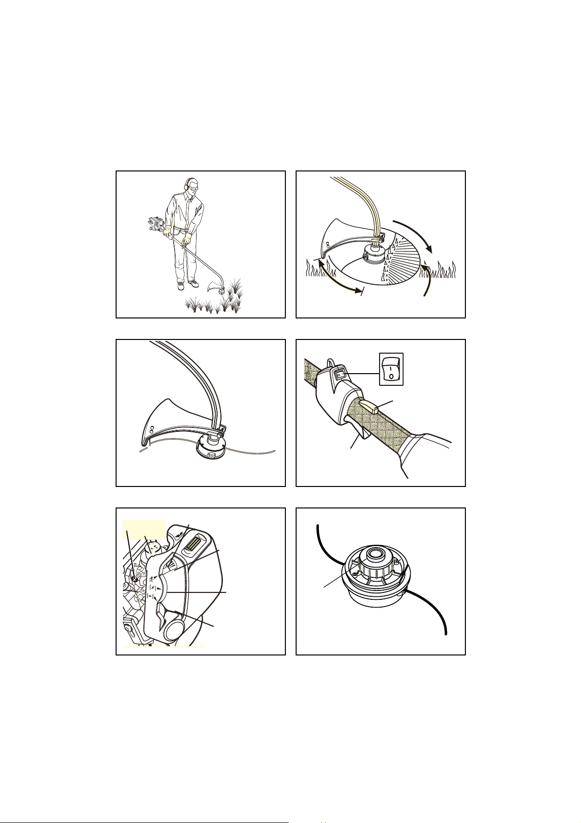
Wear full eye and hearing protection while operating this
unit.
Wear heavy long pants, boots, and gloves. Do not wear
loose fitting clothing, short pants, jewelry of any kind, or
go barefoot.
Secure long hair so it is above shoulder level to prevent
entanglement in any moving parts.
Keep all bystanders, children, and pets at least 15 m
(50 ft.) away.
Do not operate this unit when you are tired, ill, or under
the influence of alcohol, drugs, or medication.
Do not operate in poor lighting.
Keep firm footing and balance. Do not overreach.
Overreaching can result in loss of balance or exposure
to hot surfaces.
Inspect the unit before each use for loose fasteners, fuel
leaks, etc. Replace any damaged parts before use.
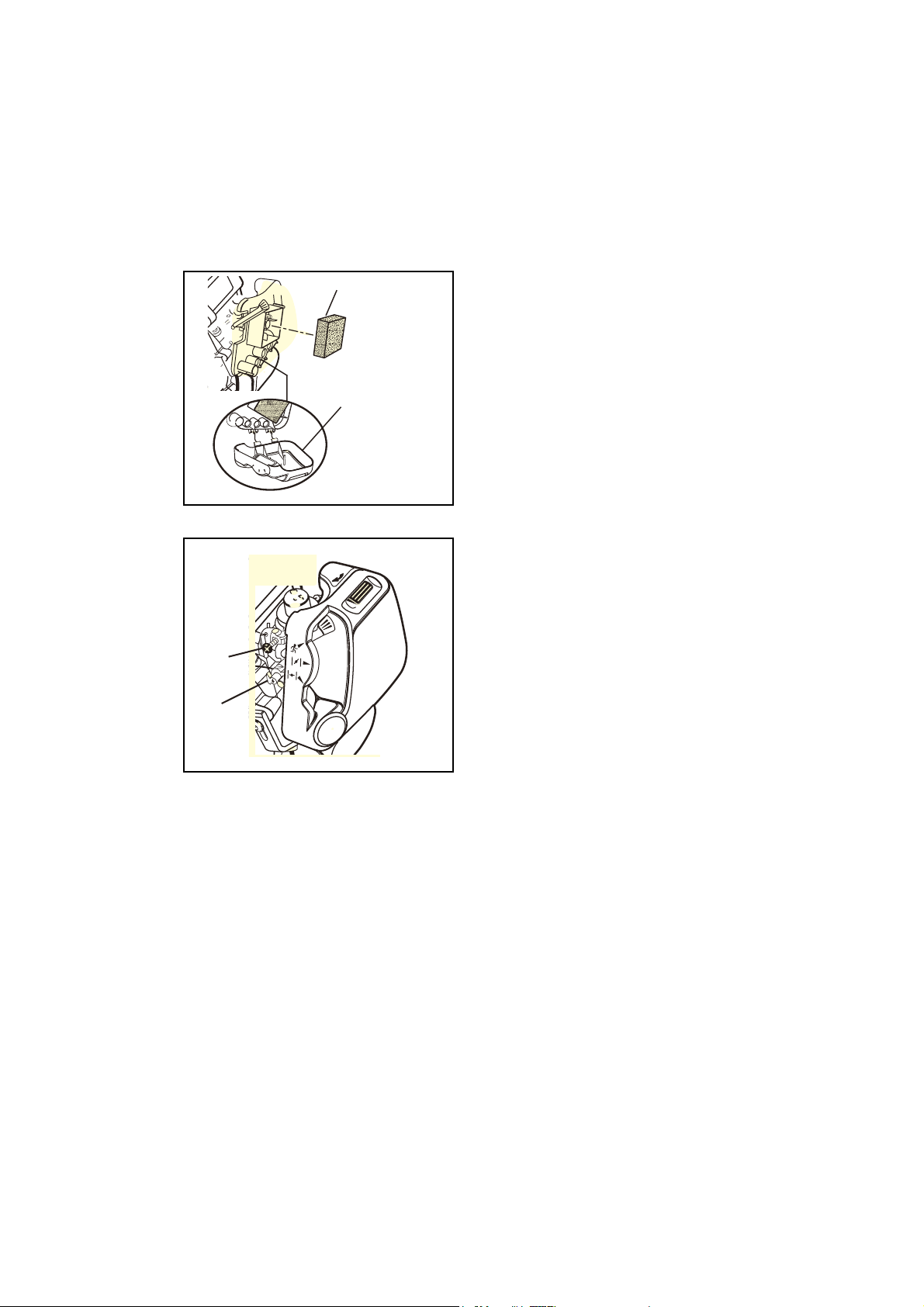
The string head or blade will rotate during carburetor
adjustments.
It has been reported that vibrations from hand-held tools
may contribute to a condition called Raynaud’s Syn-
drome in certain individuals. Symptoms may include
tingling, numbness and blanching of the fingers, usually
apparent upon exposure to cold. Hereditary factors,
exposure to cold and dampness, diet, smoking and work
practices are all thought to contribute to the develop-
ment of these symptoms. It is presently unknown what,
if any, vibrations or extent of exposure may contribute to
the condition. There are measures that can be taken by
the operator to possibly reduce the effects of vibration:
a) Keep your body warm in cold weather. When operat-
ing the unit wear gloves to keep the hands and wrists
warm. It is reported that cold weather is a major
factor contributing to Raynaud’s Syndrome.
b) After each period of operation, exercise to increase
blood circulation.
c) Take frequent work breaks. Limit the amount of
exposure per day.
d) Keep the tool well maintained, fasteners tightened
and worn parts replaced.
If you experience any of the symptoms of this condition,
immediately discontinue use and see your physician
about these symptoms.
Mix and store fuel in a container approved for gasoline.
Mix fuel outdoors where there are no sparks or flames.
Wipe up any fuel spillage. Move 9 m (30 ft. ) away from
refueling site before starting engine.
Stop the engine and allow to cool before refueling or
storing the unit.
Allow the engine to cool; empty the fuel tank and secure
the unit from moving before transporting in a vehicle.
Keep all parts of your body away from any moving part.
Do not touch area around the muffler or cylinder of the
trimmer/brushcutter, these parts get hot from operation.
Always stop the engine and remove the spark plug wire
before making any adjustments or repairs except for
carburetor adjustments.
Make sure all guards, straps, deflectors and handles are
properly and securely attached.
Use only the manufacturer's replacement string in the
cutting head. Do not use any other cutting attachment.
Never operate unit without the grass deflector in place
and in good condition.
Thank you for buying a Ryobi trimmer.
Your new trimmer has been engineered and
manufactured to Ryobi’s high standard for dependability,
ease of operation, and operator safety. Properly cared
for, it will give you years of rugged, trouble-free
performance.
WARNING
To reduce the risk of injury, the user must read
and understand the operator’s manual.

Weight
Without fuel and string head
Without fuel, w/string head
Fuel tank volume
Cutting swath
Engine displacement
Maximum engine performance
(in accordance with ISO 8893)
Maximum rotational frequency of the spindle
Engine speed (rotational frequency) at
recommended max. spindle rotational frequency
Engine speed (rotational frequency) at idle
Fuel consumption (in accordance with ISO 8893)
at max. engine performance
Specific fuel consumption (in accordance with ISO 8893)
at max. engine performance
Vibration level idling
Front handle
Rear handle
Vibration level racing
Front handle
Rear handle
Sound pressure level (in accordance with
EN ISO 11806:1997, ISO 7917:1987)
Sound power level (in accordance with ISO 10884)
4.63Kg
4.44 Kg
425 cm
3
432 mm
25 cm
3
0.75kW
9,000 min
-1
12,500 min
-1
3,100 -4,3 00 min
-1
0.48 kg/h
0.46 kg/h
4.8 m/s
2
4.8 m/s
2
13.0
8.4
100
113
- 2 -
Maintain a firm grip on both handles while trimming. Keep
string head below waist level. Never cut with the string
head located over 76 cm (30 in.) or more above the
ground.
SPECIFIC SAFETY RULES FOR TRIMMER USE
SPECIFIC SAFETY
BRUCHCUTTER
SPECIFICATIONS
DESCRIPTION OPERATION
ASSEMBLY
GRASS DEFLECTOR (FIG. 2)
1.
Remove wing nut (14), flat washer (16), lock washer (15),
and bolt (12) from the Ownerís Kit.
2.
Place grass deflector (5) over shaft (3) and bracket (13).
3.
Install bolt through the slots in the tabs on grass
deflector and bracket on driveshaft housing.
4.
Install flat washer, lock washer and wing nut.
NOTE:Do not attempt to remove or modify the spacer. This
spacer limits the upper position of the handle grip.
4.
Tighten Securely.
FRONT HANDLE (FIG. 3)
1.
Remove the front handle, bolt and wing nut from the
Owner's Kit.
2.
Install the front handle onto the top side of the shaft
housing and move it to a conforable position.
3.
Place the bolt through the front handle as shown. Then
install the wing nut.
.
Tighten the wingnutsecurely.
NOTE:: Make sure the bent end of the muffler guard (20 ) fits
securely into the opening of the rear housing (21).
SILENCER GUARD ASSEMBLY (FIG. 4)
1.
Remove muffler guard (10) and two screws (19) from the
owner's kit.
2.
Attach the muffler guard to the rear housing (18).
3.
Install two screws.
43.
Filter
44. Air Filter Cover
FUEL AND REFUELING
HANDLING THE FUEL SAFELY
Always handle fuel with care, it is highly flammable.
Always refuel outdoors where there are no sparks and
flames. Do not inhale fuel vapors.
Do not let petrol or oil come in contact with your skin.
Keep petrol and oil away from the eyes. If gasoline or
oil comes in contact with the eyes, wash them immedi-
ately with clean water. If irritation is still present, see a
doctor immediately.
Clean up spilled fuel immediately.
3.
Tighten screws securely.
1. Starter Grip
2. Front Handle
3. Shaft
4. Throttle Trigger
5. Grass Deflector
6. Trimming Line
7. Spring Head
8. Switch
9. Spacer
10. Muffler Guard
11. Choke Lever
12. Bolt
13. Bracket
14. Wing Nut
15. Lock Washer
16. Flat Washer
17. Mixture Needle
18. Rear Housing
19. Screw For Muffer Guard
20. Bent End of Guard
21. Open In Rear Housing
23. Dangerous Cutting Area
24. Best Cutting Area
25.
Direction Of Rotation
26.
Throttle Inter Lock
27.
Primer Bulb
28.
Ide Speed Screw
29. Run Position
30. Half Choke Position
31. Cold Start Postion
33. Spool Retainer
34. Spool
35. Eyelets
36.
Tab of Air Filter Cover
37. Slots
38. Spring
39. Arrows On Spool
40. Anchor Hole
41. First String
42. Second String
22. Torx Wrench
32. Connector
Read the operation manual and follow all
warnings and safety instructions.
Wear eye protection and ear protection.
Keep all bystanders, especially children
and pets, at least 15m from the operating
area

- 3 -
OPERATION
MIXING THE FUEL
This product is powered by a 2-cycle engine and requires
pre-mixing petrol and 2-cycle oil. Pre-mix unleaded
petrol and 2-cycle engine oil in a clean container
approved for petrol.
This engine is certified to operate on unleaded petrol
intended for automotive use with an octane rating of 87
([R + M] / 2) or higher.
Do not use any type of pre-mixed petrol/oil from fuel
service stations, this includes the pre-mixed gasoline/oil
intended for use in mopeds, motorcycles, etc.
WARNING:
4. Prior to replacing the fuel cap, clean and inspect the
gasket.
5. Immediately replace fuel cap and hand tighten. Wipe up
any fuel spillage. Move 9 m (30 ft.) away from refueling
site before starting engine.
NOTE: It is normal for smoke to be emitted from a new
engine during and after first use.
Use high a quality 2-cycle self mixing oil for air cooled
engines. Do not use automotive oil or 2-cycle outboard
oil.
Mix 2% oil into the
petrol
. This is a 50:1 ratio.
Mix the fuel thoroughly and also each time before
fueling.
Mix in small quantities. Do not mix quantities larger than
usable in a 30 day period. A 2-cycle oil containing a fuel
stabilizer is recommended.
FILLING THE TANK
1. Clean surface around fuel cap to prevent contamination.
2. Loosen fuel cap slowly to release pressure and to keep
fuel from escaping around the cap.
3. Carefully pour fuel mixture into the tank. Avoid spillage.
50:1 Synthetic oil.
25:1 Mineral oil.
Always shut off engine before fueling. Never add fuel
to a machine with a running or hot engine. Move at
least 9 m (30 ft.) from refueling site before starting
engine. Do not smoke!
1 Litre + 20 ml =
2 Litres + 40 ml =
3 Litres + 60 ml =
4 Litres + 80 ml =
5 Litres + 100 ml =
50:1
OPERATING THE TRIMMER (FIG. 5)
Hold the trimmer with the right hand on the rear handle and
the left hand on the front handle. Keep a rm grip with both
hands while in operation.Trimmer should be held at a
comfortable position with the rear handle about hip height.
Always operate trimmer at full throttle. Cut tall grass from
the top down.This will prevent grass from wrapping around
the shaft housing and string head which may cause damage
from overheating. If grass becomes wrapped round the
string head, stop the engine, disconnect the spark plug
wire, and remove the grass. Prolonged cutting at partial
throttle will result in oil dripping from the silencer .
ADVANCING THE STRING
ADVANCING STRING USING THE EZ LINE™ TAP
ADVANCE SYSTEM
String advance is controlled by tapping string head on grass
while running engine at full throttle.
1. Run engine at full throttle.
2. Tap string head on ground to advance string. String
advances each time the head is tapped.
3. Several taps may be required until string strikes the cut
off blade.
4. Resume trimming.
NOTE: If the string is worn too short you may not be able to
advance the string by tapping it on the ground. If so, STOP
THE ENGINE, and manually advance the string.
ADVANCING THE STRING MANUALLY
Push the spool retainer down while pulling on string(s) to
manually advance the string.
CUTTING TIPS (FIG. 6)
Keep the trimmer tilted toward the area being cut; this is
the best cutting area (24).
Do not cut in dangerous cutting area (23).
Use the tip of string to do the cutting; do not force string
head into uncut grass.
Wire and picket fences cause extra string wear, even
breakage. Stone and brick walls, curbs, and wood may
wear string rapidly.
Avoid trees and shrubs. Tree bark, wood moldings,
siding, and fence posts can easily be damaged by the
string.

- 4 -
OPERATION
GRASS DEFLECTOR LINE TRIMMING CUT-
OFF BLADE (FIG. 7)
This strimmer is equipped with a line trimming cut-off blade
on the grass deflector. For best cutting, advance string until
it is trimmed to length by the cut-off blade. Advance string
whenever you hear the engine running faster than normal.
This will maintain best performance and keep string long
enough to advance properly.
STARTING AND STOPPING (FIG. 8 & 9)
WARNING:
TO START A WARM ENGINE:
1.
Move choke lever to run position.
2.
Hold trigger and pull starter grip (1) until engine runs.
TO START A COLD ENGINE:
1.
Lay trimmer on a flat, bare surface. Move Ignition Switch (8)
NOTE:
Unit is equipped with a positive on-off switch. Make
sure switch is in the "I" (RUN) position before starting the
unit.
3. Set choke lever to choke position (31).
4.
Depress throttle interlock (26), squeeze throttle trigger (4)
5.
Set choke lever to half choke position .
6.
Run engine 30 to 45 seconds at full throttle with trigger
depressed fully) on half choke position (30) to warm up.
Move choke lever to run position (29).
Never start or run the engine inside a closed or poorly
ventilated area; breathing exhaust fumes can kill.
MAINTENANCE
WARNING:
Use only original manufacturer's replacement parts,
accessories and attachments. Failure to do so can
cause possible injury, poor performance and may
void your warranty.
You may make adjustments and repairs described here.
For other repairs, have the trimmer serviced by an
authorized servicing dealer.
Consequences of improper maintenance may include
excess carbon deposits resulting in loss of performance
and discharge of black oily residue dripping from the
silencer .
Make sure all guards, straps, deflectors and handles are
properly and securely attached to avoid the risk of
personal injury.
6. Make sure the string head and the spool retainer are
installed on the connector (32) by turning the retainer
clockwise to tighten.
7. Pull the strings again to rotate the spool into cutting
position. Push the spool retainer down while pulling on
string(s) to manually advance the string and to check for
proper assembly of the string head.
SPOOL REPLACEMENT
EZ LINE™ TAP ADVANCE SYSTEM
NEW PREWOUND SPOOL (FIG. 10 & 11)
If replacing string only, refer to “String Replacement” later in
this manual.
Use only 2.0mm (.080 in.) diameter monofilament string.
Use the manufacturer's replacement string for best perfor-
mance.
1. Stop the engine, disconnect the spark plug wire. Hold
the string head and unscrew the spool retainer (33). Turn
anti-clockwise.
2. Remove the empty spool from the string head. Keep the
spring (38) attached to the spool ( 34).
3. To install the new spool, make sure the two strings are
captured in the slots opposite each other on the new
spool. Make sure the ends of each string is extended
approximately 152 mm (6 in.) beyond each slot.
4.
Thread the strings into the eyelets (35) in the string head (
36
).
Carefully push the spool into the string head (gently pull
the strings to the outside if necessary). When the spool
is positioned in the string head, grasp the strings and pull
sharply to release them from the slots (37)in the spool.
5. Push down and turn the spool counterclockwise until it
no longer turns. Hold the spool down and rotate clock-
wise a small amount. Release the spool. The spool
should be locked down in the string head. If not, hold
down and rotate until locked.
STRING REPLACEMENT (FIG. 12 - 15)
1. Stop the engine, disconnect the spark plug wire.
Hold the string head and unscrew the spool retainer.
Turn anticlockwise.
2. Remove the spool from the string head. NOTE:
Keep the spring attached to the spool. Remove any
old string remaining on the spool.
to "I" (run) postion.
2. Push primer bulb (27) 4 times.
until engine tries to run. (No more than 3 pulls.)
5.
Hold trigger and pull starter grip until engine runs.
TO START AND STOP THE ENGINE:
1.
To stop the engine, depress the switch to "O" position.
NOTE:
Be sure to return the stop switch to the "I" (RUN)
position before trying to start unit.

- 5 -
5. Repeat above step with second string (42), using the
bottom part of spool. Do not overfill.
6. Replace the spool and the spool retainer. Refer to
"Spool Replacement " earlier in this manual.
MAINTENANCE
CLEANING THE EXHAUST PORT AND MUFFLER
Depending on the type of fuel used, the type and amount of
oil used, and/or your operating conditions, the exhaust port
and muffler may become blocked with carbon deposits. If
you notice a power loss with your gas powered tool, a
qualified service technician will need to remove these
deposits to restore performance.
SPARK ARRESTER
The spark arrester must be cleaned or replaced every 25
hours or yearly to ensure proper performance of your
product. Spark arresters may be in different locations
depending on the model purchased. Please contact your
nearest service dealer for the location of the spark arrester
for your model.
Cleaning Instructions:
Remove the spark arrester from the muffler.
If your spark arrester is made of a fiberglass material,
discard and replace.
If your spark arrester is made of a metal material follow
these cleaning instructions:
1. Spray the spark arrester with a quality carbon
cleaner.
2. Gently clean using a wire brush.
3. Install the new or cleaned spark arrester and reas-
semble completely before use.
REPLACING AND CLEANING AIR FILTER (FIG. 16 & 17)
For proper performance and long life, keep air filter (43) clean.
1.
Remove the air filter cover (44) by pushing down on the tab (36)
with your thumb while gently pulling on the cover.
2. Remove the filter, clean it in warm soapy water. Rinse
and let dry completely. For best performance, replace
annually.
3. Installthefilter,aligntabs,push in,andmakesurethe
The fuel cap contains a non-serviceable filter and a check
valve. A clogged fuel filter will cause poor engine perfor-
mance. If performance improves when the fuel cap is
loosened, check valve may be faulty or filter clogged.
Replace fuel cap if required.
SPARK PLUG
This engine uses a Champion RCJ-6Y with 0,63 mm (.025
in.) electrode gap. Use an exact replacement and replace
annually.
WARNING:
FUEL CAP
STORAGE (1 MONTH OR LONGER)
1. Drain all fuel from tank into a container approved for
petrol. Run engine until it stops.
2. Clean all foreign material from the trimmer. Store it in a
well-ventilated place that is inaccessible to children.
Keep away from corrosive agents such as garden
chemicals and de-icing salts.
3. Cover the blade with the blade protector before storing
the unit, or during transportation.
4. Abide by all ISO and local regulations for the safe
storage and handling of petrol. Excess fuel should be
used up in other 2-cycle engine powered equipment.
A leaking fuel cap is a fire hazard and must be
replaced immediately.
3. Cut two pieces of string, each being approximately
2.7 m (9 ft.) long.
4. Insert the first string (41) into the anchor hole (40) in the
upper part of the spool (34). Wind the first string around
the upper part of the spool counterclockwise, as
shown by the arrows on the spool (39). Place string in
the slot on upper spool flange, leaving about 152
mm (6 in.) extended beyond the slot. Do not overfill.
After winding the string, there should be at least 6
mm (1/4 in.) between the wound string and the
outside edge of the spool.
latches are locked into place.

- 6 -
TROUBLESHOOTING
PROBLEM POSSIBLE CAUSE SOLUTION
IFTHESE SOLUTIONS DO NOT SOLVETHE PROBLEM CONTACTYOUR AUTHORISED SERVICE DEALER.
1. Check spark. Remove spark plug. Reattach the
spark plug cap and lay spark plug on metal
cylinder. Pull the starter rope and watch for
spark at spark plug tip. If there is no spark,
repeat test with a new spark plug.
2. Push primer bulb until bulb is full of fuel. If bulb
does not fill, primary fuel delivery system is
blocked. Contact a servicing dealer. If primer
bulb fills, engine may be flooded (see next
item).
3. Remove spark plug, turn trimmer so spark plug
hole is aimed at the ground. Make sure lever is
in the “WARM START” position and pull starter
cord 10 to 14 times. This will clear excess fuel
from engine. Clean and reinstall spark plug.
With the throttle trigger fully depressed, pull
starter cord three times with lever at “WARM
START” position. If engine does not start,
move choke lever to “COLD START” and follow
normal starting instructions in "STARTING
AND STOPPING" section. If engine still fails to
start, repeat procedure with a new spark plug.
4. Contact a servicing dealer.
Contact a servicing dealer.
Turn mixture needle (17) anticlockwise 1/16 turn.
1. Use fresh fuel and the correct 2-cycle oil mix.
2. Clean air filter. Refer to “Replacing and
Cleaning Air Filter” earlier in this manual.
3. Turn mixture needle clockwise 1/16 turn.
Turn idle speed screw (28) clockwise to increase
idle speed (Fig. 18).
1. Lubricate with silicone spray.
2. Install more string. Refer to "String Replacement"
earlier in this manual.
3. Pull strings while alternately pressing down on
and releasing spool retainer.
4. Remove string from spool and rewind. Refer to
"String Replacement" earlier in this manual.
5. Advance string at full throttle.
Engine will not start:
Engine starts but will not
accelerate:
Engine starts but will not
run at high speed at half
Engine does not reach full
speed and emits excessive
smoke:
Engine starts, runs, and
accelerates but will not idle:
String will not advance:
1. No spark.
2. No fuel.
3. Flooded engine.
4. Starter rope pulls harder now than
when new.
Carburetor requires adjustment.
1. Check oil fuel mixture.
2. Air filter dirty.
3. Carburetor requires adjustment.
Carburetor requires adjustment.
1. String welded to itself.
2. Not enough string on spool.
3. String worn too short.
4. String tangled on spool.
5. Engine speed too slow.
choke: (Fig. 18)

-7-
TROUBLESHOOTING
1. Cut tall grass from the top down.
2. Operate trimmer at full throttle.
Clean threads and lubricate with grease - if no improve-
ment, replace spool retainer.
1. Operate trimmer at full throttle.
2. Use fresh fuel and the correct 2-cycle oil mix.
3. Clean per instruction in Maintenance Section.
4. Turn “Mixture” needle clockwise 1/16 - 1/8 turn(Fig. 18).
1. Cutting tall grass at ground
level.
2. Operating trimmer at part
throttle.
Screw threads dirty or damaged.
1. Operating trimmer at part
throttle
2. Check oil/fuel mixture.
3. Air filter dirty.
4. Carburetor requires adjust-
ment.
Grass wraps around
shaft housing and string
head:
Spool retainer hard to
turn:
Oil drips from muffler:
PROBLEM POSSIBLE CAUSE SOLUTION
IFTHESE SOLUTIONS DO NOT SOLVETHE PROBLEM CONTACTYOUR AUTHORISED SERVICE DEALER.
NOTE: The carburetor adjustment needle(s) are equipped with plastic cap(s) that prevents counterclockwise rotation from
the original factory adjustment. If your unit exhibits specific performance problem(s) where theTrouble Shooting Section
recommends a counterclockwise needle adjustment and no adjustments have been made since original purchase, the unit
should be taken to a factory authorised service dealer for repair. In most cases, the needed adjustment is a simple task for
the factory trained service representative.

RYOBI TECHNOLOGIES AUSTRALIA PTY.LTD.
GUARANTEE
RYOBI TECHNOLOGIES AUSTRALIA PTY. LTD.
A.B.N. 98 002 277 509
Contact during normal business hours.
RYOBI NEW ZEALAND PTY. LTD.
AUCKLAND:
27 Clemow Drive, Mt Wellington, N.Z.
Contact during normal business hours.
Subject to the guarantee condition below, this Ryobi tool
(hereinafter called “the product”) is guaranteed by Ryobi
(hereinafter called “the Company”) to be free from
defects in material or workmanship for a period of 24
months from the date of original purchase covering
both parts and labour. Under the terms of this
guarantee, the repair or replacement of any part shall
be the opinion of the Company or its authorised agent.
Should service become necessary during the warranty
period, the owner should contact the RYOBI HELPLINE
1300 361 505 or contact the retailer from whom the
product was purchased.
In order to obtain guarantee service, the owner must
present the sales docket and Guarantee Certificate
to confirm date of purchase. This product is sold by the
dealer or agent as principal and the dealer has no
authority from the Company to give any additional
guarantee on the Company’s behalf except as herein
containedorhereinreferred to.
Guarantee Conditions
This guarantee only applies provided that the Product
has been used in accordance with the manufacturer’s
recommendations under normal use and reasonable
care (in the opinion of the Company) and such
guarantee does not cover damage, malfunction or
failure resulting from misuse, neglect, abuse, or used
for a purpose forwhich it was not designed or is not
suited and no repairs, alterations or modifications
have been attempted by other than an Authorised
Service Agent.This guarantee will not apply if the tool is
damagedbyaccident or if repairs arise from normal
wear and tear.
The Company accepts no additional liability pursuant to
this guarantee for the costs of travelling or
transportation of the Product or parts to and from the
service dealer or agent - such costs are not included in
this guarantee.
Certain legislation, including the Trade Practices Act,
1974 (as amended) and other state and territorial laws
give rights to the buyer and impose liability on the seller in
certain circumstances. Nothing herein shall have the effect
of excluding, restricting or modifying any condition,
guarantee, right or liability imposed, to the extent only
that such exclusion, restriction or modification
would render any term herein void.
BRISBANE : All enquiries Tel : 1300 361 505
TOWNSVILLE: All enquiries Tel : 1300 361 505
MELBOURNE:
HOBART: All enquiries Tel : 1300 361 505
ADELAIDE: All enquiries Tel : 1300 361 505
PERTH: 33-35 Sorbonne Cres. Canning Vale, W.A. 6155
Address Of Dealer
Present This Form With Your Purchase Docket When Guarantee Service Is Required.
Tel: 1300 361 505 - Fax: 1800 807 993 - www.ryobi.com.au
Tel: (09) 573 0230 - Free Call: 0800 279 624 - Fax: (09) 573 0231 - www.ryobi.co.nz
For your record and to assist in establishing date of purchase (necessary for in-guarantee service)
please keep your purchase docket and this form completed with the following particulars.
This Guarantee Form Should Be Retained By The Customer At All Times
Date Model No Serial No
Tel : (08) 9455 7775
SYDNEY: Building B, Rosehill Industrial Estate, 3 - 5 Shirley Street, Rosehill N.S.W. 2142
All enquiries Tel : 1300 361 505
Table of contents
Other Ryobi Trimmer manuals

Ryobi
Ryobi ONE+ P2607 User manual

Ryobi
Ryobi RHT25X55R User manual

Ryobi
Ryobi HT920Dr User manual

Ryobi
Ryobi 725rE User manual

Ryobi
Ryobi 2075RC User manual

Ryobi
Ryobi RHT700RL User manual

Ryobi
Ryobi PLT3043S Instructions for use

Ryobi
Ryobi PLT-3043YA Instructions for use

Ryobi
Ryobi RHT1850SLi20 User manual

Ryobi
Ryobi OHT1850 User manual

Ryobi
Ryobi RLT1825Li13 User manual

Ryobi
Ryobi OLT1831 User manual

Ryobi
Ryobi RY402011 User manual

Ryobi
Ryobi RY40602 User manual

Ryobi
Ryobi OHT1850X User manual

Ryobi
Ryobi RHT5555RSH User manual

Ryobi
Ryobi RY24200 User manual

Ryobi
Ryobi RLT36X4BL User manual

Ryobi
Ryobi RY30520 User manual

Ryobi
Ryobi RLT-710 Operation manual