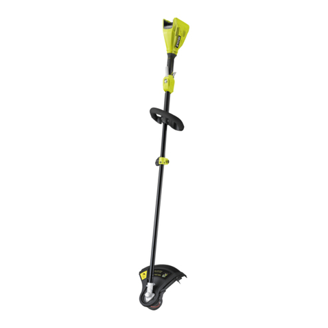
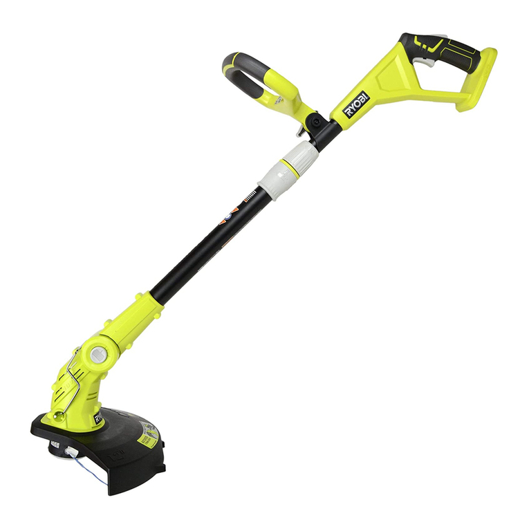
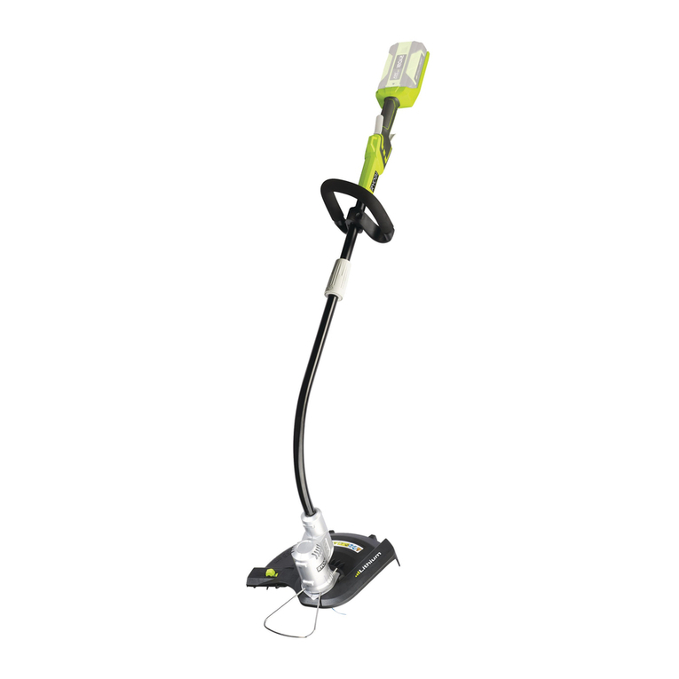
Ryobi RY24200 Quick setup guide

RYOBI
24 VOLT STRING TRIMMER
MODEL NO. RY24200
ALL VERSIONS
REPAIR SHEET

RYOBI 24 VOLT STRING TRIMMER – MODEL NUMBER RY24200
2
Figure A
7
16 17
8
9
2
1
3
4
6
18
10
12
11
13
15
14
5
See Figure B
See Figure B
19 20

RYOBI 24 VOLT STRING TRIMMER – MODEL NUMBER RY24200
3
KEY PART
NO. NUMBER DESCRIPTION QTY
1 31108517G Power Head Assembly ........................................................................................................................................................1
2 31302517G Adjustable Front Handle.......................................................................................................................................................1
3 3290205G Hex Nut (M6) ........................................................................................................................................................................1
4 3410605AG Clamp...................................................................................................................................................................................1
5 34104517G Handle Knob ........................................................................................................................................................................1
6 33303517G Guide (Flower Bed)...............................................................................................................................................................1
7 3110382G Spool w/Line (AC14RSL)......................................................................................................................................................1
8 3411546-7G Spool Cap ............................................................................................................................................................................1
9 31107517G Grass Deflector Assembly....................................................................................................................................................1
10 099627001005 Warning Icon Label (Power Head)........................................................................................................................................1
11 099627001004 Data Label (Power Head) .....................................................................................................................................................1
12 099627001003 Logo Label ...........................................................................................................................................................................1
13 099627001009 Warning Icon Label (Boom) ..................................................................................................................................................1
14 099628001003 Boom Warning Label............................................................................................................................................................1
15 099627001006 Data Label (Boom)................................................................................................................................................................1
16 099627001007 Adjustable Cutting Width Label............................................................................................................................................1
17 099627001001 Automatic Line Feed Label ..................................................................................................................................................1
18 099628001001 Rotation Arrow Label............................................................................................................................................................1
19 679034001 Compression Spring.............................................................................................................................................................1
20 310920001 Slider Assembly....................................................................................................................................................................1
NOT SHOWN
OP140 Charger.................................................................................................................................................................................1
OP241 Battery..................................................................................................................................................................................1
988000396 Operator’s Manual
8-19-11
(REV:02)
1 1
2 1
3 1
4 1
5 1
6 1
7 1
8 1
9 1
10 1
11 1
12 1
13 1
14 1
15 1
16 1
17 1
18 1
19 1
20 1
21 31
22 1
23 1
24 1
25 1
26 2
27 000000000 Logo Label ................................ 2
28 000000000 Warning Label............................ 1
NOT SHOWN
00000000 Battery ....................................... 1
00000000 Charger...................................... 1
988000396 Operator’s Manual ..................... 1
3-3-11
(REV:01)
PARTS LIST (FIGURE A)
The model number will be found on a label attached to the motor housing. Always mention the model number of your String Trimmer
when requesting service or ordering repair parts.
RYOBI 24 VOLT STRING TRIMMER – MODEL NUMBER RY24200
4
17
20
See Figure A
4
3
13
13
19
5
19
22
14
15
15
16
9
9
9
9
9
21
23
24
10
11
12
9
2
6
1
1
7
8
18
25
Figure B

RYOBI 24 VOLT STRING TRIMMER – MODEL NUMBER RY24200
5
1 31301517G Handle Assembly ..............................................................................................................................................................1
2 34101517G Trigger ...............................................................................................................................................................................1
3 36301517G Switch ...............................................................................................................................................................................1
4 34106517G Motor Mounting Plate .......................................................................................................................................................1
5 32200517G Screw w/Washer ...............................................................................................................................................................2
6 31109459G Contact Plate ....................................................................................................................................................................1
7 33901517G Compression Spring .........................................................................................................................................................1
8 34103517G Lock-Out Button ...............................................................................................................................................................1
9 32201517G Screw (M4 x 14 mm) .......................................................................................................................................................28
10 31105517G Upper Boom Assembly.....................................................................................................................................................1
11 34113508-1G Coupler .............................................................................................................................................................................1
12 31106517G Lower Boom Assembly (Inc. Key No. 25) .........................................................................................................................1
13 31303517G Pivot Housing Assembly ...................................................................................................................................................1
14 34107517G Cover Plate .......................................................................................................................................................................1
15 31304517G Adjustment Pedal Assembly .............................................................................................................................................1
16 34105517G Coupler Ring .....................................................................................................................................................................1
17 31100339G Pivot Assembly .................................................................................................................................................................1
18 31101517G Motor Assembly (Inc. Key Nos. 4-5) .................................................................................................................................1
19 31305517G Motor Housing Assembly..................................................................................................................................................1
20 31101345G Line Head..........................................................................................................................................................................1
21 34109517G Edger Wheel......................................................................................................................................................................1
22 33304517G Cutting Blade ....................................................................................................................................................................1
23 32901131G Retaining Ring...................................................................................................................................................................1
24 34108517G Guard ................................................................................................................................................................................1
25 31109517G Male Plug ..........................................................................................................................................................................1
PARTS LIST (FIGURE B)
KEY PART
NO. NUMBER DESCRIPTION QTY
The model number will be found on a label attached to the motor housing. Always mention the model number of your String Trimmer
when requesting service or ordering repair parts.
RYOBI 24 VOLT STRING TRIMMER – MODEL NUMBER RY24200
6
SWITCH
PLUG
PLUG
BLACK
CONTACT PLATE
WIRE CONNECTOR
WIRE CONNECTOR
BLACK
BLACK
BLACK
RED
MOTOR
RED
RED
RED
WIRING DIAGRAM
Other manuals for RY24200
3
Table of contents
Other Ryobi Trimmer manuals

Ryobi
Ryobi OHT1850H User manual

Ryobi
Ryobi C430 RY34421 User manual

Ryobi
Ryobi P2004 User manual

Ryobi
Ryobi RPT3600 User manual

Ryobi
Ryobi RBC30SET User manual

Ryobi
Ryobi RLT-1000EX User manual

Ryobi
Ryobi P601 User manual

Ryobi
Ryobi RLT183113 Operation instructions

Ryobi
Ryobi RLT1825M20S User manual

Ryobi
Ryobi One+ R18HTR22 User manual

Ryobi
Ryobi PLT3043S User manual

Ryobi
Ryobi RLT3025S User manual

Ryobi
Ryobi RBC-1000EX User manual

Ryobi
Ryobi RLT1038 User manual

Ryobi
Ryobi OHT1855R User manual

Ryobi
Ryobi 725rE User manual

Ryobi
Ryobi R36HTRBL User manual

Ryobi
Ryobi RY18HT40A User manual

Ryobi
Ryobi RHT36 User manual

Ryobi
Ryobi RLT1238 User manual