RZB MWEB User manual

EMERGENCY LIGHTING SYSTEM
MWEB
MWEB
SUPERVIS IO N U NI T F OR EMERGEN CY LIGHTIN G SYST EMS
WITH E T H ER N ET I N TER FA C E AND INT EGRATED W EB- S ERV ER
VERSION 2.01

1. THE MWEB EMERGENCY LIGHTING SYSTEM AND ITS ELEMENTS............................4
2. INSTALLATION................................................................................................................... 4
3. START OF THE SOFTWARE.............................................................................................4
4. NAVIGATOR WINDOW.......................................................................................................6
4.1. COMMUNICATION-WINDOW.................................................................................................7
4.2. UNIT INFORMATION...........................................................................................................7
4.3. MODIFICATION OF PARAMETERS: ......................................................................................10
4.4. MAIN WINDOW / EXISTING FAULT-LIST:................................................................................11
4.5. MAIN WINDOW / FAULT LIST: ...........................................................................................12
4.6. MAIN WINDOW / TEST RESULT.........................................................................................13
4.7. ALL TESTS....................................................................................................................14
4. . ADMINISTRATOR CONFIGURATION....................................................................................15
4.9. GENERAL CONFIGURATION............................................................................................1
4.10. NETWORK/MAIL CONFIGURATION..................................................................................20
4.11. NEW CONFIGURATION..................................................................................................21
4.12. TEST CONFIGURATION.................................................................................................22
4.13. DELETE EMERGENCY LIGHTING UNITS:............................................................................23
4.14. SPECIAL FEATURE – REMOTE CONTROL........................................................................23
4.15. FTP TRANSFER........................................................................................................24
5. FIRMWARE.......................................................................................................................24
5.1 UPGRADING THE APPLICATION WITH AUTOUPDATE................................................................25
6. RETURN TO FACTORY SETTINGS / RESTART..............................................................26
7. SIZE AND WEIGHT..........................................................................................................27
Revision history:
2.00, 2017-05-01 – Updates for the new firmware, supporting operation with and without
olle tor boxes
2.01 2017-07-13 – Add unified en losure dimensions. En losure for assembly with and without
LCD display
V E R S I O N 2 . 1 1 3 . 7 . 1 7 / M W E B _ U S E R G U I D E _ E N . O D T
- 2 / 2 8 -

(1) Communi ation line (Meter-Bus) 4) Colle tor box (C-Box)
(2) Main line (Meter-Bus) (5) MWEB
(3) Emergen y lighting units (6) PC with Web browser
V E R S I O N 2 . 1 1 3 . 7 . 1 7 / M W E B _ U S E R G U I D E _ E N . O D T
- 3 / 2 8 -

1. The MWEB Emergency lighting system and its elements
MWEB is used as a entral supervision unit in the system. There is a y li information
ex hange between the MWEB unit and ea h emergen y lighting unit. The MWEB is
ontinuously s anning the whole installation and gathering information about all emergen y
lighting units.
Note that the emergen y lighting operation of ea h emergen y lighting unit is totally
independent of the supervision done by MWEB. Even in ase of ommuni ation failure,
emergen y operation is guaranteed.
The information from the MWEB is dispat hed through DUROBOX (4) on entrator units.
Up to 125 emergen y lighting units (3) (only SRM-type units) an be onne ted to ea h
DUROBOX ( onne tion 1) and up to 63 DUROBOX units an be onne ted to a MWEB
( onne tion 2). All together 7875 emergen y lighting units an be monitored from a
MWEB unit.
The MWEB unit is a WEB-server and an be onne ted to any LAN-Network
ommuni ating using the TCP-IP proto ol. When addressed by a Web-Navigator software
like Internet-Explorer, the MWEB unit an transmit all the information it has gathered from
the emergen y lighting units. This information is transmitted as HTML pages whi h are
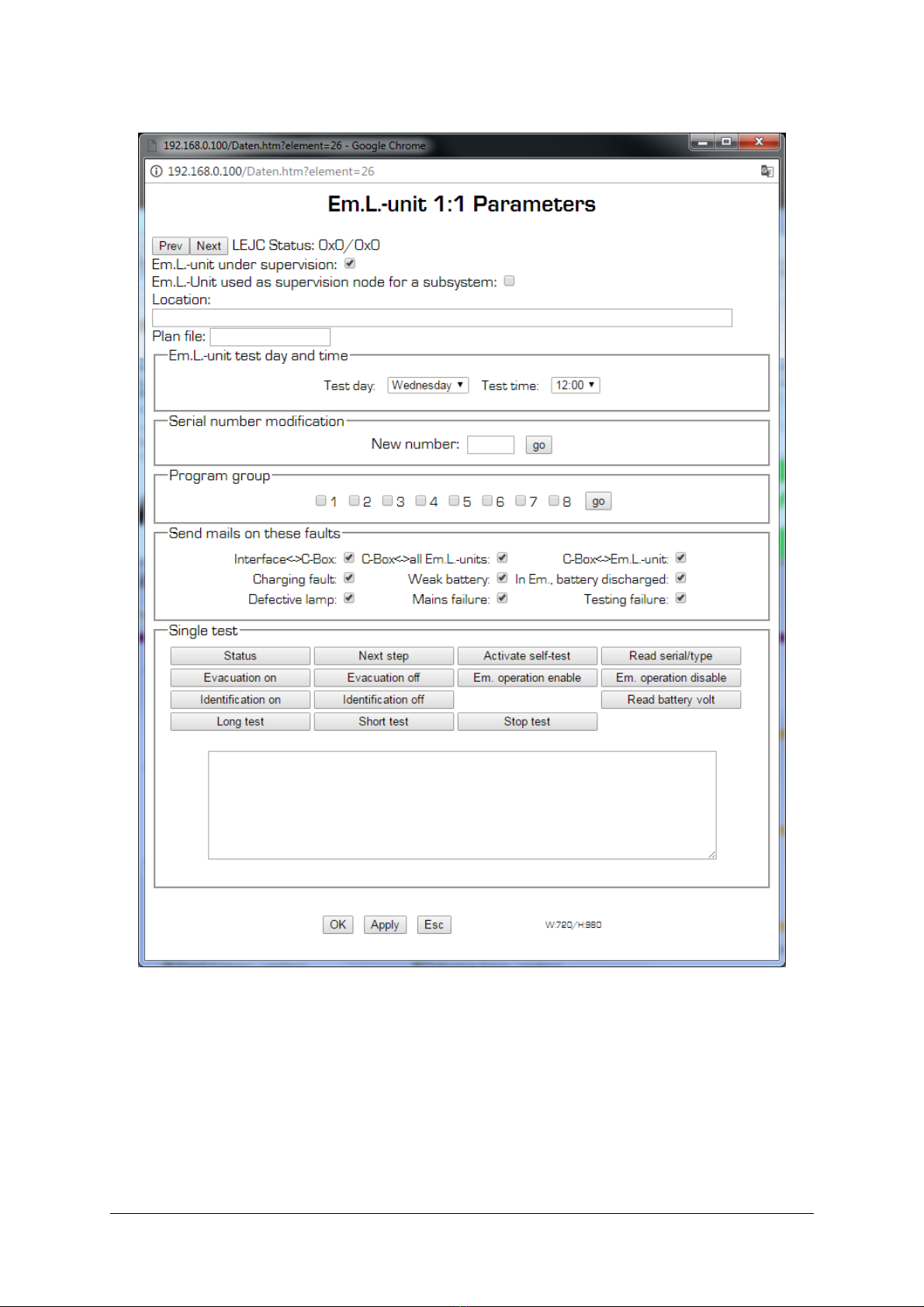
shown by the navigator software. Using the same software, it is also possible to hange the
onfiguration of the MWEB unit or of ea h emergen y lighting unit.
The MWEB supervision software main tasks are the following:
Coordination of the self-testing timing of all the emergen y lighting units
Re ording of all faults
Storage of all information on erning ea h emergen y lighting unit
Automati Configuration of the System
Data prote tion through password
Sending email notifi ations for system status
2. Installation
The MWEB unit has to be onne ted to the mains (85-264VAC, 47-63Hz) for its supply
and to the lo al network using a standard Ethernet RJ45 8-pin onne tor (dire t).
The default value of the MWEB unit (fa tory setting) IP-address is 192.168.0.100. This
address an be hanged through the navigator software using the menu item
" onfiguration-general", or through the system serial interfa e. This hange will be
des ribed further more thoroughly, and should only be performed by a system
administrator.
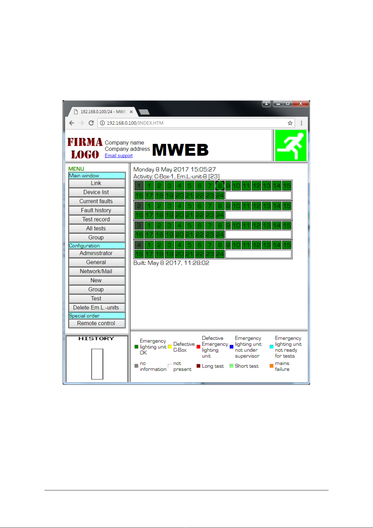
3. Start f the s ftware
The software an be a essed by using the web browser, at URL address
http://xxx.xxx.xxx.xxx (where is the IP-address hosen for the MWEB unit).
V E R S I O N 2 . 1 1 3 . 7 . 1 7 / M W E B _ U S E R G U I D E _ E N . O D T
- 4 / 2 8 -

The onfiguration an be then adjusted by using the menu item "Configuration general".
Additional network and email notifi ations onfiguration is available in the menu item
„Network/Email“
The MWEB systems supports two operating modes:
•dire t onne tion to SRM devi es (up to 125 devi es an be ontrolled).
•Indire t onne tion through the Colle tor Boxes (63 * 125 devi es an be
ontrolled)
The operating mode onfiguration is provided with the “C-Box support” he kbox in the
General onfiguration dialog.
To examine the MWEB operation, demo mode an be sele ted, whi h will simulate the
some features allowing to use the user interfa e.. This is enabled with the “MWEB demo”
he kbox.
The next step is the automati system onfiguration, if it has not yet be done, or is not
available through another method. The MWEB unit will find all the units onne ted to the
system. The menu item is " onfiguration new".
The starting is des ribed with more details in the hapter 4.7 "General Configuration" and
the automati onfiguration in the hapter "New Configuration".
When the software has been started, and the onfiguration reated or upgraded, the
MWEB unit begins with the monitoring of all the emergen y lighting units whi h are
registrered in the onfiguration data bank.
User password for onfiguration at MWEB is : HEUREKA
Admin password for onfiguration at MWEB is : 1234567
V E R S I O N 2 . 1 1 3 . 7 . 1 7 / M W E B _ U S E R G U I D E _ E N . O D T
- 5 / 2 8 -

4. Navigat r wind w
When the ommuni ation has been established with the MWEB unit, the following window
is shown on the omputer:
-T p left:
Logo or other information. This area is reated with the html file FRM_HEAD.TXT lo ated
on the SD ard in the USER folder. Short des ription of ustomization options are on the
SD ard in file /USER/README.TXT. Files on the SD ard ould be a essed through the
FTP, with user/password redentials.
-T p right:
"running man emergen y logo": It gives a global information about the emergen y lighting
system. This logo is green when everything is OK, and red-yellow blinking when there is at
least one emergen y lighting fault in the system.
-Center right:
Main system status area, as shown above is for non- onfigured system
-Center left:
system menu links for system display options and onfiguration – all onfigurations are
password prote ted.
-B tt m left:
This area indi ates the level of filling of the fault-list. This fault-list an have up to 1'000 fault
re ordings. As soon as 900 faults have been re orded, an E-Mail an be sent to the
monitoring supervisor (his address has to be transmitted to the MWEB unit). The
supervisor must then pro eed with the downloading of the fault-list and its printing and/or
saving, in order to erase the existing fault-list inside the MWEB unit.
-B tt m right:
Color legend for the statuses shown of the Emergen y Lighting Units.
V E R S I O N 2 . 1 1 3 . 7 . 1 7 / M W E B _ U S E R G U I D E _ E N . O D T
- 6 / 2 8 -

4.1. C mmunicati n-wind w
It is important to know that the a tualization of the window is made only by the navigator
software, and not by the MWEB unit. The MWEB unit is monitoring the installation
independently of the navigator software, and addresses one unit per se ond. Ea h 10
se onds, the navigator software fet hes from MWEB the a tual status of the installation.
This status is shown as des ribed on the following pi ture, i.e. all emergen y lighting units
onne ted to the same olle tor box shown in one table, and ea h unit pi tured with a olor
orresponding to its status. The olor legend is shown on the bottom line.
The unit with a thi k dark border is the unit being urrently a essed.
4.2. Unit Inf rmati n
By li king on the re tangle orresponding to one emergen y lighting unit on the window
des ribed above, all the information on erning this unit (and stored in the MWEB unit)
appears on the s reen as shown below:
V E R S I O N 2 . 1 1 3 . 7 . 1 7 / M W E B _ U S E R G U I D E _ E N . O D T
- 7 / 2 8 -

Prev/Next:
Sele ts previoius/next element from the devi es list
Change parameters:
Opens the window where all the parameters on erning the unit an be modified (see
paragraph below for a detailed des ription).
Type inf rmati n:
These information are only displayed for EE emergen y lighting units and MBUS2EE
olle tor-boxes (Extended Units). MWEB re ognize automati ally this type of units.
Test day / Test time:
It is possible to define and re ord when the self-testing of ea h unit has to take pla e. Note
that the sequen e is defined by the unit itself and not by the supervision software in the
MWEB unit.
As the battery is fully dis harged after a monthly test, it is important to perform these tests
when the han e of having somebody present in the room is very small. It is also important
to insure that two adja ent fittings are not going to be tested at the same time. For that
reason, the emergen y lighting units an be divided in two groups, one with all units having
even numbers, the other one with all units having odd numbers. It is then possible to define
a test-day and a test-time for ea h group.
It is also possible to define an individual test day and time for ea h emergen y lighting (see
paragraph 4.1.1.1.)
Last Test:
V E R S I O N 2 . 1 1 3 . 7 . 1 7 / M W E B _ U S E R G U I D E _ E N . O D T
- 8 / 2 8 -

Gives the date when the last self-testing has been performed. Note that, if the omputer
has been dis onne ted or if the ommuni ation has been interrupted for a long period,
then the unit has been testing itself using its own internal lo k, and in that ase, the date
re orded in the omputer may be erroneous. When the ommuni ation is working again,
the testing date using the unit internal lo k has not been re orded by the unit, and
therefore annot be transmitted to the omputer.
Installati n:
Gives the date when the emergen y lighting unit has been re orded in the onfiguration file.
FL-Lamp changed / Charging fault cleared / Batt. Changed :
Give the dates when the battery or the fluores ent lamp were last hanged, or when an
eventual harging fault was last leared. Note that this information is given by the unit itself
to the MWEB unit.
If the battery has been tested and reported faulty (after a monthly long duration self-
testing), the unit is waiting for the faulty battery to be dis onne ted and for a new one to be
onne ted. As soon as this has been done, and when the unit is asked for its status by the
MWEB unit, it reports that the battery has been hanged. The date of reporting is
re orded inside the MWEB unit.
If the fluores ent lamp has been tested and reported faulty (after a weekly self-testing), the
unit tries to strike the lamp during a few se onds ea h minute. As soon as the faulty lamp
has been hanged (after max. 1 minute), the unit reports ba k this hange to the MWEB
unit.
C-B x fault I:
(only for C-Boxes) Indi ates that the ommuni ation between the C-box and MWEB is faulty
or interrupted.
C-B x fault II:
(only for C-Boxes) Indi ates that the ommuni ation between the C-box and all the
emergen y lighting units onne ted to it is faulty or interrupted.
L cati n / Plan:
It is possible to allo ate a text or graphi al file to ea h emergen y lighting unit, in order to
des ribe the lo ation of the emergen y lighting unit. This file an be of any type.
V E R S I O N 2 . 1 1 3 . 7 . 1 7 / M W E B _ U S E R G U I D E _ E N . O D T
- 9 / 2 8 -

4.3. M dificati n f parameters:
Em.L.-unit under supervision:
By selecting „unchecked“, it is possible to disable the monitoring of this unit, without
removing it from the configuration. This means that faults related to this unit will not
be recorded nor shown. This feature is typically used when one unit is removed for
maintenance or completely switched off (including battery) because of building
renovation.
Em.L.-Unit used as supervision node for a subsystem:
V E R S I O N 2 . 1 1 3 . 7 . 1 7 / M W E B _ U S E R G U I D E _ E N . O D T
- 1 /2 8 -

By selecting „checked“, the unit act as a supervision node for a subsystem instead as
an Em.L.-Unit. In this case the „charging fault“ ie replaced by the „subsystem fault“.
Using this window, it is possible to define or modify both the location and the plan file.
The plan file is located in the MWEB SD card unit. This file has to be stored in the
„PICTURES“ directory which can be accessed with FTP transfer.
It is also possible to change the bus number of the emergency lighting unit. Just tip
the new number and click on „go“ to proceed to the change.
The emergency lighting unit can also join one or more groups. Just select the group
and click on „go“ to proceed to the change.
When a fault is detected, the MWEB unit is able to send E-Mails to the installation
supervisors (name „admin“). Just select on the fault list, the faults for which the E-
Mail has to be sent.
You can also make single tests with one unit. Results will appear in the bottom text
area.
4.4. Main wind w / existing fault-list:
When an emergen y lighting unit reports a fault to the MWEB unit, this fault will be
re orded automati ally. In the above shown window, all the existing registered faults are
shown, listed by C-Box number and Em.-l. Unit serial number order. This window is
automati ally refreshed ea h 10 se onds, so that it is possible to be informed about the
status of the installation just by leaving the navigator software running and this window
opened.
V E R S I O N 2 . 1 1 3 . 7 . 1 7 / M W E B _ U S E R G U I D E _ E N . O D T
- 11/ 2 8 -

4.5. Main wind w / Fault list:
Date - Time Indi ates the date and time of the re orded fault.
C-Box/Em.L.-unit Serial number of the faulty emergen y lighting unit and
the orresponding C-Box.
Fault Fault des ription
Lo ation Lo ation of the unit (as registered in the MWEB unit)
Help What has most likely to be done to repair the emergen y
lighting.
The faults are re orded and listed a ording to their order of appearan e. They remain
listed, even when the emergen y lighting has been repaired. This window is not refreshed
ea h 10 se onds.
Up to 1000 faults an be re orded. When more faults have to be re orded, the older faults
are being erased. The filling status of the fault-list is shown on the bottom left part of the
window. The installation supervisor an empty this list (see „ onfiguration general“).
In order to save the fault-list on the Computer, the following pro edure has to be done:
-right mouse li k on the fault-list.
-in the menu, hoose „show sour e text“
-in the text editor, hoose „save under...“
- hoose a name anding with.htm, and a dire tory where the history has to be re orded.
By opening the file in this dire tory, it is possible to print it or save it on disk or CD-ROM.
V E R S I O N 2 . 1 1 3 . 7 . 1 7 / M W E B _ U S E R G U I D E _ E N . O D T
- 12 / 2 8 -

4.6. Main wind w / Test result
This table contents the following information:
–Date of installation
–Date of the first duration test (commissioning test)
–Date of the last good started test and test type
–Failure at the present time
–Date of the last battery change
–Date of the cleared charging fault
–Date of the of the last FL change
–Location
V E R S I O N 2 . 1 1 3 . 7 . 1 7 / M W E B _ U S E R G U I D E _ E N . O D T
- 13 / 2 8 -

4.7. All tests
This picture show s all the tests that have been executed. Under each year the
executed test weeks should be displayed. If you select one week you can see the
test results off all the emergency units in this week (see the next picture).
The MWEB save the last test result for four year ago. The test result shall be saved
one time a week. The saving day and time should be configured in the menu
„configuration test“.
V E R S I O N 2 . 1 1 3 . 7 . 1 7 / M W E B _ U S E R G U I D E _ E N . O D T
- 14 / 2 8 -

4.8. Administrat r C nfigurati n
-Passw rds
The installation supervisor will have to hoose and onfirm a password.
He will be alled „admin“ (administrator) and will have the right to modify everything.
He an also modify the „
user
“ password. This is very useful if the user has lost his password
-Test durati n
The administrator an de rease the test duration from 3 hours units to one hour.
V E R S I O N 2 . 1 1 3 . 7 . 1 7 / M W E B _ U S E R G U I D E _ E N . O D T
- 15 / 2 8 -

-Serial number ( nly f r EE units)
If the administrator knows the serial number of an unit, he an retrieve or
reprogram the bus number of this unit.
After a bus number reprogramming, you have to integrate this unit with its new bus
number in the onfiguration with „
Configuration-new
“.
-Start/St p test
The administrator an start or stop fun tion and duration tests for all or a part of units in
the installation. The test will only start if the Em.L.-Unit is ready for tests.
V E R S I O N 2 . 1 1 3 . 7 . 1 7 / M W E B _ U S E R G U I D E _ E N . O D T
- 16 / 2 8 -

-Start/St p identificati n
The administrator an start or stop identifi ation for all or a part of units in the installation.
During identifi ation the status led is blinking Red/Green. This identifi ation status led is
only blinking if the Em.L.-Unit is not faulty.
The identifi ation blinking is automati ally stopped by the Em.L.-Unit after one hour.
It an also be manually stopped by depressing the „Stop“ push button.
V E R S I O N 2 . 1 1 3 . 7 . 1 7 / M W E B _ U S E R G U I D E _ E N . O D T
- 17 / 2 8 -

4.9. General C nfigurati n
The following parameters an be defined or midified:
-Language
-Passw rd
The installation supervisor will have to hoose and onfirm a password.
He will be alled „user“ and will have the right to modify everything ex ept the
administrator password.
He an also define a login password. In this ase the server an be a essed as
„admin“ and his password or as „user“ with the login password.
-Server name
Name of the MWEB server
-Date and time setting:
The MWEB unit has an internal lo k, in order to register the faults. Use the
orresponding fields to modify and/or adjust the lo k data.
-Fault list filling state:
When the fault-list has to re ord more than 1'000 faults, the oldest one will be
erased. In order to prevent this, the fault list should be regularly emptied (press on
„erase“)
ATTENTION: before erasing the existing list, the fault-list should be re orded and
printed. Please see paragraph 4.3 to save the fault-list.
V E R S I O N 2 . 1 1 3 . 7 . 1 7 / M W E B _ U S E R G U I D E _ E N . O D T
- 18 / 2 8 -

-Evacuati n:
By sele ting „enable“ and then „OK“ at the bottom, all the emergen y lighting units
will be able to be swit hed on and running in emergen y mode (i.e. dis harging their
batteries) by losing a lo al onta t on the MWEB unit. This an be used for
example in ase of fire. This lo al onta t is between RTS and CTS on the system
RS232 interfa e of the MWEB unit (normally open, emergen y operation when
losed).
-Devices scan cycle time:
Setting of the time interval between a esses for two devi es (between one Em.L.-
unit and the next one).
V E R S I O N 2 . 1 1 3 . 7 . 1 7 / M W E B _ U S E R G U I D E _ E N . O D T
- 19 / 2 8 -

4.10. Netw rk/mail C nfigurati n
-Mail C nfigurati n
The MWEB unit an send automati ally E-Mails to the installation supervisor, for
example when the fault list is almost (90%) full.
The E-Mail parameters are usually given by your Internet Provider.
You an hose beatween sending a mail at ea h appearing of a fault or one time a
day or one time a week or one time a month.
-TCP/IP parameters:
The MWEB unit is a WEB server, belonging to a lo al network, or to Internet. It
needs a IP Address. If the MWEB unit has to send E-Mail over a gateway, the IP
addresses of the gateway and of the DNS server have also to be re orded. These
datas should be re orded by the network administrator.
V E R S I O N 2 . 1 1 3 . 7 . 1 7 / M W E B _ U S E R G U I D E _ E N . O D T
- 2 / 2 8 -
Table of contents
Other RZB Lighting Equipment manuals
Popular Lighting Equipment manuals by other brands

JONATHAN Y
JONATHAN Y JYL3050 instructions

Clas Ohlson
Clas Ohlson LS9A123-1-01 quick start guide

Ecco
Ecco Reflex 5500 Series Installation and operation instructions

Lightmaxx
Lightmaxx VEGA DOT 60 user manual

Clevertronics
Clevertronics EL EUBPRO-SM-LI Installation & maintenance instructions

Diamante
Diamante GLOWLINE HO 600 user manual

Larson Electronics
Larson Electronics RL-15-LED-CPR operating instructions

Amark
Amark PARMATRIX 25 user manual

olympia electronics
olympia electronics GR-415/4P quick guide

Image Engineering
Image Engineering LG4 user manual

Situ Lighting
Situ Lighting LightBob manual

Stoane Lighting
Stoane Lighting BPX Installation and maintenance instructions