s::can con::cube D-330 User manual

Manual
con::cube D-330
January 2020 Release
S-45-M


Table of Contents
1 General 5
2 Safety Guidelines 6
2.1 Declaration of Conformity 6
2.2 Special Hazard Warning 6
3 Technical Description 7
3.1 Intended Use 7
3.2 Functional Principle 7
3.3 Product 8
3.4 Storage, Transport and Disposal 10
3.5 Scope of Delivery 11
3.6 Product Updates, Other 11
4 Installation 12
4.1 Environment 12
4.2 Mounting 12
5 Initial Startup 13
5.1 Plan of Terminal Connections 13
5.2 Connection of s::can Spectrometer Probe 14
5.3 Connection of s::can ISE Probes and Sensors 14
5.4 Connection of Cleaning Devices 15
5.5 Connection of Main Power Supply 15
5.6 Starting up of Operation Software 16
5.7 con::cube Sleep Mode 16
6 Operation of con::cube 17
6.1 Direct Operation of con::cube 17
6.2 Remote Operation of con::cube 17
6.2.1 Remote Operation of con::cube via Web-Browser 17
6.2.2 Remote Operation of con::cube via Terminal Program (VNC-Viewer) 18
6.3 con::cube Interfaces 18
6.4 con::cube Network Integration and Security 19
6.5 con::cube Connection Types 20
6.5.1 Connectivity via Network Cable (RJ45) 20
6.5.2 Connectivity via WLAN 20
6.5.3 Connectivity via 3G Modem 21
6.5.4 Connectivity via VPN 22
7 Data Management 23
7.1 Data Storage 23
7.2 Data Transfer 23
7.3 Data Types 23
7.4 Data Transfer via Modbus Interface 25
7.5 DataTransferviaProbusDPInterface 29
7.6 Data Transfer via SDI12 Interface 29
8 Functional Check 30
8.1 Check System / Monitoring Station 30
con::cube D-330, 01-2020 Release
www.s-can.at
Copyright © s::can Messtechnik GmbH
3 / 42

9 Maintenance 31
9.1 Cleaning 31
9.2 Desiccant Package 31
9.3 Housing 31
9.4 Calibration Touch Screen 31
10 Troubleshooting 32
10.1 Device Settings 32
10.2 Software Update 32
10.3 Return Consignment (RMA - Return Material Authorization) 32
11 Accessories 33
11.1 Installation 33
11.1.1 Weather Shield 33
11.1.2 Power Supply Cord 33
11.1.3 External Antenna and Connector 34
11.2 Automatic Cleaning 35
11.2.1 Cleaning Valve 35
11.3 Spare Parts 35
11.3.1 Desiccant Package 35
11.3.2 Touch Pen 35
11.4 Optional Features 36
11.4.1 Gateway to 3G Modem 36
11.4.2 Analog Output Module 36
11.4.3 Digital Output Module 36
11.4.4 ProbusDPOutputModule 36
11.4.5 SDI 12 Output Module 37
11.4.6 Analog Input Module 37
11.4.7 Digital Input Module 37
12 TechnicalSpecications 38
12.1 Terminal Connections for optional I/O Modules 40
12.2 PinAssignmentforoptionalProbusDPconnector(Sub-D9) 40
con::cube D-330, 01-2020 Release Copyright © s::can Messtechnik GmbH
www.s-can.at4 / 42

1 General
Thismanualcontains,rstly, general information (chapter 1) and safety guidelines (chapter 2).Thenextchapter(chapter
3) provides a technical description of the s::can product itself as well as information regarding transport and storage of the
product. In further chapters the installation (chapter 4) and the initial startup (chapter 5) are explained. Furthermore information
regarding calibration of the device (chapter 6), data management (chapter 7), how to perform a functional check (chapter 8)
and maintenance (chapter 9) can be found in this manual. Information regarding troubleshooting (chapter 10), the available
accessories(chapter11)andthetechnicalspecications(chapter12)completethedocument.
Each term in this document that is marked italic and underlined, can be found on the display of your controller for operation
or as lettering on your s::can product.
In spite of careful elaboration this manual may contain errors or incompletion. s::can does not assume liability for errors or
loss of data due to such faults in the manual. The original manual is published in English and German by s::can. This original
manual serves as the reference in case discrepancies occur in versions of the manual after translation into third languages.
Thismanualandallinformationandgurescontainedthereinarecopyrighted.Allrights(publishing,reproduction,printing,
translation, storage) are reserved by s::can Messtechnik GmbH. Each reproduction or utilisation outside the permitted limits of
the copyright law is not allowed without previous written consent from s::can Messtechnik GmbH. The reproduction of product
names, registered trade names, designation of goods etc. in this manual does not imply that these names can be used freely
by everyone; often these are registered trade marks, even if they are not marked as such.
This manual, at the time of its publication (see release date printed on the top of this document), concerns the s::can products
listedinchapter3.Informationandtechnicalspecicationsregardingtheseitemsins::canmanualsfromearlierreleasedates
are herewith replaced by this manual.
The electronic version (pdf-document) of this manual
is available on the s::can Customer Portal (Services for
Customer) of the s::can Homepage (www.s-can.at).
con::cube D-330, 01-2020 Release
www.s-can.at
Copyright © s::can Messtechnik GmbH
5 / 42

2 Safety Guidelines
Installation, electrical connection, initial startup, operation and maintenance of any s::can product as well as complete
s::can measuring systems must only be performed by qualied personnel. This qualied personnel has to be trained and
authorisedbytheplantoperatororbys::canfortheseactivities.Thequaliedpersonnelmusthavereadandunderstoodthis
manual and have to follow the instructions contained in this manual.
For proper initial startup of complete s::can measuring systems, the manuals for the controller and software used for operation
(e.g. con::lyte, con::cube, con::nect, moni::tool), the connected probes and sensors as well as the used additional devices (e.g.
compressor) have to be consulted.
The operator has to obtain the local operating permits and has to comply with the joint constraints associated with these.
Additionally, the local legal requirements have to be observed (e.g. regarding safety of personnel and means of labour,
disposal of products and materials, cleaning, environmental constraints). Before putting the measuring device into operation,
the operator has to ensure that during mounting and initial startup - in case they are executed by the operator himself - the
local legislation and requirements (e.g. regarding electrical connection) are observed.
All s::can products are leaving our factory in immaculate technical and safety conditions. Inappropriate or not intended use of
the product, however, can cause danger! The manufacturer is not responsible for damage caused by incorrect or unauthorised
use. Any kind of manipulation of the instrument is strictly prohibited - except for the activities described in this document.
Conversions and changes to the device must not be made, otherwise all certications and guarantee / warranty become
invalid. For details regarding guarantee and warranty please refer to our general conditions of business.
2.1 Declaration of Conformity
This s::can product has been developed, tested and manufactured for electromagnetic compatibility (EMC) and according to
applicableEuropeanstandards,asdenedinthedeclarationofconformity.
CE-marks are applied on the device. The declaration of conformity related to this marking can be requested from s::can or your
local s::can sales partner or can be downloaded from the s::can Customer Portal.
2.2 Special Hazard Warning
Because the s::can measuring systems are frequently installed in industrial and communal waste water applications,
one has to take care during mounting and demounting of the system, as parts of the device can be contaminated
with dangerous chemicals or pathogenic germs. All necessary precautions should be taken to prevent endangering of
one’s health during work with the measuring device.
!
con::cube D-330, 01-2020 Release Copyright © s::can Messtechnik GmbH
www.s-can.at6 / 42
!

3 Technical Description
3.1 Intended Use
Thecon::cubeisanhigh-performance,powerecientindustrialcomputerforon-lineoperationofs::canspectrometerprobes
(spectro::lyser, nitro::lyser, carbo::lyser, etc.) and i::scan as well as ISE probes (e.g. ammo::lyser) and all other s::can sensors
(e.g. pH::lyser, oxi::lyser). Furthermore readings of third party sensors can be integrated via standard interfaces. Once
connectedtoprobesandsensorsthecon::cubefulllsalltasksofacompletemonitoringstationduetothefollowingscopeof
functions:
Numerical and graphical display of the readings from the connected measuring devices
Simple initialisation of spectrometer probes, i::scan, ISE probes and sensors
Simple initialisation and parameterisation of s::can infrastructure (e.g. automatic cleaning devices)
Parameter calibration of spectrometer probes, i::scan, ISE probes and sensors
Storage of measurement results and all other station information in a local database
Transfer of measurement results via Modbus RTU/TCP interface
Transfer of measurement results via analog outputs (optional)
TransferofmeasurementresultsviaProbusDPinterface(optional)
Transfer of measurement results via SDI12 interface (optional)
TransferofmeasurementresultsviaFTPletransfer
Potential free digital output relay triggered by current reading (optional)
Integration of external sensor signals via RS485 input
Integration of external sensor signals via analog input (optional)
Integration of external sensor signals via digital input (optional)
Network connectivity via ethernet, WLAN or optional 3G/4G modem
Remote control of s::can monitoring station via ethernet, WLAN or optional 3G/4G modem
Data synchronisation to central data collection systems via ethernet, WLAN or optional 3G/4G modem
Display of current and historical readings
Alarming depending on water quality monitored
Triggering depending on water quality monitored
Inalltypesofapplications,therespectiveacceptablelimits,whichareprovidedinthetechnicalspecicationsintherespective
s::can manuals, have to be observed. All applications falling outside of these limits, and which are not authorised by s::can
Messtechnik GmbH in written form, do not fall under the manufacturer’s liability.
The device must only be used for the purpose described in this manual. Use in applications not described in this manual, or
modicationofthedevicewithoutwrittenagreementfroms::can,isnotallowed.s::canisnotliableforclaimsfollowingfrom
such unauthorised use. In such a case, the risks are the sole responsibility of the operator.
3.2 Functional Principle
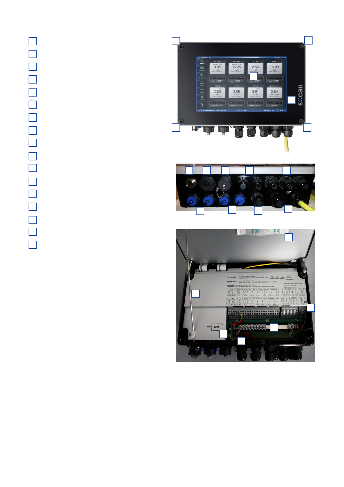
The con::cube is equipped with an operation software (moni::tool) that can be operated via a color graphical display with touch
functionality. The software starts automatically when the con::cube is powered up. The con::cube collects readings for probes
and sensors using a digital bus connection. It displays the data, stores all information and makes it available for further use.
con::cube D-330, 01-2020 Release
www.s-can.at
Copyright © s::can Messtechnik GmbH
7 / 42

3.3 Product
The following device variants of the con::cube are available. Regarding detailed information of the device variants, please refer
tothetechnicalspecicationslocatedattheendofthismanual.
Type Specication
D-330-230 Station control terminal with 100-240 VAC, 50-60 Hz power supply
D-330-024 Station control terminal with 10-36 VDC power supply
D-330-TOUCH Display and touch screen input module
D-315-3GLX 3G modem (OS Linux)
D-315-OUT-PROFIBUS ProbusDP(outputmodule)
D-315-OUT-SDI12 SDI 12 (output module)
D-315-OUT-MA 2 analog outputs (output module)
D-315-OUT-RELAY 4 digital outputs (output module)
D-315-IN-MA 2 analog inputs for integration of third party readings (input module)
D-315-IN-RELAY 2 digital inputs for integration of third party readings (input module)
D-315-ANTENNA-PLUG internal antenna adapter cable and connector
D-315-ANTENNA-PRO external, high range antenna, incl. 10 m extension cable
D-303-LX LicenceLinuxapplication(xinstalledOS)
S-20-MVA Complete license including moni::tool (all features), vali::tool and ana::tool
Thedeviceistypiedbyatypelabel,asshownontheright,thatcontainsthefollowinginformation:
Manufacturer’s name and country of origin
Severalcerticationmarks
Device name (con::cube)
Type of power supply
Bar code
Device serial number (S/N)
Information on power supply
Environment rating (IP)
Acceptable humidity limits
Acceptable temperature limits
Item number (Type)
QR code
con::cube D-330, 01-2020 Release Copyright © s::can Messtechnik GmbH
www.s-can.at8 / 42

Color graphical display with touch screen
Screw to open housing cover
Control LED (blue, yellow or red)
1 connector for s::can spectrometer probe
4 connectors for i::scan, ISE probes or sensors
Ethernet (LAN) connector
USB connector
2cableglandsM16(optionalforProbus)
3 cable glands M16
1 cable gland M16 (optional antenna plug)
2 cable glands M20
Holder for housing cover
Desiccant package
Insert for SIM card
Additional cable terminals for 12 VDC out
Grounding bar
Power supply connection
con::cube D-330, 01-2020 Release
www.s-can.at
Copyright © s::can Messtechnik GmbH
9 / 42
1
2
2
2
2
3
4
510
5
76 8 9
11
1
2
4
5
6
7
3
8
9
10
11
12
13
14
15
16
17
16
17
12
13
14
15

Ensure correct orientation of mounting rails. Top of con::cube
hastobetiltedbackwardstopreventanywaterowingoverthe
touch screen or entering the housing when device is opened.
Dimensions of con::cube in mm
3.4 Storage, Transport and Disposal
Thelimitingvaluesfordevicestorageandtransport,whicharedescribedinthesectiontechnicalspecications,havetobe
observed at all times. The device shall not be exposed to strong impacts, mechanical loads or vibrations. The device should
be kept free of corrosive or organic solvent vapours, nuclear radiation as well as electromagnetic radiation.
Damage to the device caused by wrong storage will not be covered by warranty.
Transport should be done in a packaging that protects the device (original packaging or protective covering if possible).
This product is marked with the WEEE symbol to comply with the European Union’s Waste Electrical & Electronic
Equipment (WEEE) Directive 2012/19/EC. The symbol indicates that this product should not be treated as household
waste. It must be disposed and recycled as electronic waste. Please assist to keep our environment clean.
Take care that no sharp-edged or heavy objects are placed on the housing cover, which might scratch and / or
damage the touch screen.
con::cube D-330, 01-2020 Release Copyright © s::can Messtechnik GmbH
www.s-can.at10 / 42
!
!

3.5 Scope of Delivery
Immediately upon receipt, please check the received consignment for completeness on the basis of the delivery note and
check for any possible damage incurred during shipping. Please inform the delivering dispatcher and s::can immediately in
case of any damages in transit.
The following parts should be included in the delivery:
s::can con::cube (part-no. D-330-xxx)
Pen for touch screen
Mounting rail (2 pieces) with 4 screws (M5x8)
s::can manual con::cube (part-no. S-45-M)
The following parts could be included in the delivery if ordered as an option:
Cable for power supply (part-no. C-31-xx)
Gateway to 3G (part-no. D-315-3GLX)
Internal antenna adapter cable and connector (part-no. D-315-ANTENNA-PLUG)
External antenna (part-no. D-315-ANTENNA-PRO)
Dierent I/O modules, which are assambled into the con::cube already (part-no. D-315-OUT-MA, D-315-OUT-RELAY,
D-315-PROFIBUS, D-315-OUT-SDI12, D-315-IN-MA, D-315-IN-RELAY)
s::can weather shield for con::cube (part-no. F-51)
In case of incompleteness please contact your s::can sales partner immediately!
3.6 Product Updates, Other
Themanufacturerreservestherightstoimplement,withoutpriornotice,technicaldevelopmentsandmodicationsinthelight
of continuous product care.
con::cube D-330, 01-2020 Release
www.s-can.at
Copyright © s::can Messtechnik GmbH
11 / 42

4 Installation
4.1 Environment
The con::cube is designed according to environmental protection rating IP 65 and is resistant against environment
eects.Indooruse is preferred. Incaseof outdoor use theinstallationin a cabinet orontheseparately available
weather shield is highly recommended to protect the device (housing cover has to be securely closed).
Enclosureclass IP65protection isonlyguaranteedifthe housingcover isxedtightlywiththefourscrews, anoperative
desiccant package is mounted inside the housing and the sealing of the housing cover is undamaged and placed correctly. In
addition all cable glands have to be sealed correctly in that way they are closed tightly with the appropriate cables or dummy
caps. All connectors must be covered with corresponding caps when not in use. Any damage caused by intrusion of water will
not be covered by the warranty.
The correct installation of measuring instruments is an important prerequisite for satisfactory operation. Therefore the following
checklist for the installation can be used to ensure that all sources for potential operational problems can be ruled out to the
greatest possible extent during the installation, allowing the s::can monitoring system to operate properly.
Installation site:
Easy accessibility (mounting, sampling, functional check, demounting)
Availabilityofsucientspace(probe/sensor,installationtting,controllerforoperation,etc.)
Adherencetolimitvalues(seetechnicalspecicationslocatedattheendofthismanual)
Best possible weather and splash water proof set-up
Infrastructure (energy, data and compressed air):
Power supply for controller for operation (operational reliability, voltage, power, peak free)
Oil- and particle free compressed-air supply (optional for automatic probe / sensor cleaning)
Shortest possible distances between system components (probe – controller – compressed-air supply – energy supply)
Correct dimensioning, mounting and protection of all cables and lines (non-buckling, no risk of stumbling, no damage etc.)
4.2 Mounting
For mounting and electrical installation the following tools and materials are necessary:
Hexagonal wrench key (size 5) to open housing cover
Torxwrenchkey(sizeTX25)forxingscrewsofmountingrails
2 s::can mounting rails (included in delivery)
4screws(M5)and4washersforxingthetwomountingrailsontothecon::cube(included
in delivery)
4 screws for fastening the con::cube on the wall (if required)
Weather shield (F-51, if required)
Power supply cable (C-31-xx, if required)
Stripping tool for power supply line
Cable end sleeves and crimper
Thecon::cubecanbemountedquicklyandeasilyontoaatwallusingoneofthefollowing
methodes:
With the two mounting rails [1] included in delivery. Fasten the two mounting rails onto
the backside of the con::cube using the four screws [2] and the four spring washers [3] as
shown on the right.
With the four threaded holes on the backside of the con::cube to mount the device directly
from the backside (M5 screws, not included in delivery).
Forthecorrectdimensioningandspacerequiredformountingpleaserefertotheguresin
section3.3andthetechnicalspecications.
con::cube D-330, 01-2020 Release Copyright © s::can Messtechnik GmbH
www.s-can.at12 / 42
1
2
3
!

5 Initial Startup
Once mounting and installation of the con::cube have been completed and checked (see section 4) the initial startup of the
s::can monitoring system will require the following actions, in the order presented below:
Connect the s::can spectrometer probes (see section 5.2).
Connect the s::can ISE probes, i::scan and sensors (see section 5.3).
Connect the cleaning devices to the proper terminal connections in the cable terminal compartment (see section 5.4).
Connectofoptionaldevicesusedforthes::cannano::stationormicro::station,e.g.owdetectorF-45-ALARMorpressure
sensor F-500-P.
Establish main power supply to the con::cube (see section 5.5) and wait until the operation software moni::tool has started
up (see section 5.6).
Pleasenoteallinformationinthemoni::toolmanualforfurtherstartupandcongurationofthemonitoringsystem.
5.1 Plan of Terminal Connections
Once the housing cover has been opened (four hexagonal head screws removed) you have access to the cable terminal
compartment of the con::cube.
Opening of the cable terminal compartment must be carried out by authorised persons only (see section 2) and after
disconnecting the power supply!
Be aware that cable clamps of relay contacts you have connected to the device might also have power supply
(230 VAC), depending on how they have been interconnected!
The con::cube is equipped with spring terminals that enable quick and easy wiring.
Insert a small screwdriver into the slot above the cable clamp you want to connect (see left picture below).
Move the screwdriver upwards, which opens the cable clamp, and insert the wire (see middle picture below).
Move the screwdriver downwards and remove it. Now wire is locked in the cable clamp (see right picture below).
s::can recommends to use wires with isolated end sleeves for power supply and dater transfer.
con::cube D-330, 01-2020 Release
www.s-can.at
Copyright © s::can Messtechnik GmbH
13 / 42
!

Plan of terminal connections for con::cube D-330-230
Plan of terminal connections for con::cube D-330-024
5.2 Connection of s::can Spectrometer Probe
An s::can spectrometer probe can be connected to the external connector for spectrometer probes, which is marked with no.4
inthegureofsection3.3.Ifanextensioncableisusedthetotallengthoftheprobe‘scableshouldnotbemorethan40m.
If necessary, a con::nect box (B-23-xxx) has to be used to connect a further spectrometer probe.
5.3 Connection of s::can ISE Probes and Sensors
Alternative or additional to the spectrometer probe it is possible to connect ISE probes, i::scan and / or s::can sensors via
thesysplugconnectorslocatedonthecon::cube.Theseconnectorsaremarkedwithno.5inthegureofsection3.3.Ifan
extension cable is used the total length of the probe’s cable should not be more than 40 m.
If necessary, the distribution box (B-41-HUB) has to be used to increase the number of plugs.
con::cube D-330, 01-2020 Release Copyright © s::can Messtechnik GmbH
www.s-can.at14 / 42

Before connecting the probes or sensors, ensure that the sensor plug and connector on the con::cube are dry and
clean. Otherwise communication errors and / or device damage might occur. Connectors not in use should always be
covered with the protective cap.
5.4 Connection of Cleaning Devices
For the automatic cleaning of the probe and sensors connected, the cleaning devices have to be wired to the con::cube within
thecableterminalcompartment.Thetablebelowdisplaysthedierentpossibilitiesofconnection.
Cleaning Device Colour of wire Labelling Terminal no.
Cleaning valve via Valve 1 Blue M+ / Valve 1 6
Brown M- / Valve 1 5
Cleaning valve via Valve 2 Blue M+ / Valve 2 8
Brown M- / Valve 2 7
Autobrush via Valve 1 Purple (yellow 1)) M+ / Valve 1 6
Black (brown 1)) - / 12V Out 11 / black terminal
Red (white 1)) + / 12V Out 12 / red terminal
Autobrush via Valve 2 Purple (yellow 1)) M+ / Valve 2 8
Black (brown 1)) - / 12V Out 11 / black terminal
Red (white 1)) + / 12V Out 12 / red terminal
ruck::sack via Valve 1 Purple M+ / Valve 1 6
Black - / 12V Out 11 / black terminal
Red + / 12V Out 12 / red terminal
ruck::sack via Valve 2 Purple M+ / Valve 2 8
Black - / 12V Out 11 / black terminal
Red + / 12V Out 12 / red terminal
1) previous used cable version
Once the cleaning device has been electrically connected, the device needs to be parameterised within the moni::tool software
(please refer to manual moni::tool).
5.5 Connection of Main Power Supply
This type of work must be performed by authorised
persons only (see section 2)!
Depending on the device type, the con::cube has to be
connected to the appropriate power supply. The connection
of power supply (AC or DC, respectively), must be done with
an earthed conductor wire (PE - „protective earth“)!
The power supply earth (PE) has to be done properly
according to the corresponding norms / standards with a
max. restistance between earth grounding of power supply
andsite‘searthgroundingof0.1Ohm.
Process medium (e.g. waste water) must be connected to the
same earth ground with less than 0.5 Ohm.
The connection in the cable terminal compartment has to be performed as displayed on the table above. The ground wire (PE)
hastobeconnectedtothegroundingbarofthecon::cube,whichismarkedwithno.16inthegureofsection3.3.
A switch or circuit-breaker must be included in the power supply. It must be suitable located and easily reachable. It
must be marked as a disconnecting device for the monitoring equipment.
!
Connection of power supply for con::cube D-330-230
No / [Labelling] Assignment
55 / [P] or 56 / [P] Conductor or phase, resp.
57 / [N] or 58 / [N] Neutral wire
Connection of power supply for con::cube D-330-024
No / [Labelling] Assignment
55 / [V+] or 56 / [V+] + 24 VDC
57 / [V-] or 58 / [V-] - 24 VDC
!
con::cube D-330, 01-2020 Release
www.s-can.at
Copyright © s::can Messtechnik GmbH
15 / 42
!

5.6 Starting up of Operation Software
Once the con::cube is connected to the power supply (see section 5.5), it will show the s::can
logo for a few seconds while starting up. During the startup of moni::tool a message as shown
on the right hand side is visible. Please consider that the complete start up procedure will
require appox. 1 - 2 minutes.
When no probes and sensors have been installed yet (initial
startup), only the main window and the menu tabs are visible
on the display.
Please refer to the manual of the operation software moni::tool
for all further tasks to complete the initialisation of your s::can
monitoring system.
5.7 con::cube Sleep Mode
Foroperationwithlowpowerconsumptionaspecicsleepmodecanbeconguredonthecon::cubeviamoni::tool(Service
\ Terminal \ con::cube \ Power Save).
When using the sleep mode in combination with a 3G/4G modem, the most actual moni::tool version V3.1.4 has to be
used.Whenusinganolderversion,amodicationofajumperisneeded(informationnotehowtodothisisavailable
via s::can customer support).
con::cube D-330, 01-2020 Release Copyright © s::can Messtechnik GmbH
www.s-can.at16 / 42
!

6 Operation of con::cube
The con::cube is equipped with the operating software moni::tool and uses multi touch technology and a Web-Browser as
gracaluserinterface.Thismeansthatmoni::toolcanbeoperatedviaWeb-Browsereitherdirectlyonthetouchscreenofthe
con::cubewithyourngersand/oratouchpen(seesection6.1)orviaremoteconnectionusingaPC,notebook,tablett,etc.
(see section 6.2). Please note that only one user can operate the con::cube directly (i.e. can be logged on).
The main frame of the moni::tool display contains the following items that are visible at all times.
Tabs for navigating between the main views
Clicking on this item will open the login window or
logout window
Name of the monitoring station
Current system date and time (clicking on this icon
will display date / time of the last measurement)
Clicking on the s::can logo will callup information on
the installed software version and the controller
Scrollbar to scroll the display up and down
6.1 Direct Operation of con::cube
Normally this direct operation is performed by a person standing in front of the con::cube and using the touch screen.
Alternatively moni::tool can also be operated with a USB mouse and / or a USB keyboard. These devices can be connected to
theUSB-socket(markedwithno.7inthegureofsection3.3)ofthecon::cube.AUSB-hubcanbeusedtooperatekeyboard
and mouse simultaniously.
Please keep in mind that a few service actions (e.g. touch calibration) can be used in direct operation only (see manual
moni::tool).
6.2 Remote Operation of con::cube
For any kind of remote operation the con::cube needs to be connected to the internet, a VPN network, a local network or
directly to a PC (see section 6.5).
6.2.1 Remote Operation of con::cube via Web-Browser
The moni::tool software can be operated from any computer
that has access to the con::cube. Simply enter the IP address
of the con::cube into the address bar of your Web-Browser.
Several users can view moni::tool simultaniously but only one
user can be logged in.
User = Administrator
Password = admin1
1
2
4
5
6
3
con::cube D-330, 01-2020 Release
www.s-can.at
Copyright © s::can Messtechnik GmbH
17 / 42
1
2 3 4 5
6

6.2.2 Remote Operation of con::cube via Terminal Program (VNC-Viewer)
The terminal program VNC-Viewer can be used for direct operation of
the con::cube via remote connection. In this case keyboard, mouse and
monitor of the computer running the VNC-Viewer can be used to operate
the con::cube.
When using the VNC-Viewer a login window will pop up once the remote
connection was successful. The password to be entered is „scan“ (case-
sensitive).
If you operate the con::cube via VNC-Viewer, all actions can be seen on the
touch screen of the con::cube also.
For operation of VNC-Viewer with Linux (moni::tool Version V3) the port 5900 has to be unlocked in the con::cube
rewall.
6.3 con::cube Interfaces
Thegurebelowoersanoverviewofallavailableinterfaces,thatcanbeusedforoperationofthecon::cube.
!
con::cube D-330, 01-2020 Release Copyright © s::can Messtechnik GmbH
www.s-can.at18 / 42

6.4 con::cube Network Integration and Security
For normal operation, remote control, data transfer and other features it might be necessary to setup a connectivity of the
con::cube.Withinthissectionthedierentpossibilitiesareexplainedandsecuritybackgroundismentionedalso.
The con::cube is based on Microsoft Windows XP embedded (XPe) operating system until moni::tool versions V2.5. From
Version 3.0 on it is based on a Linux operating system (Debian).
While the XPe platform is well-proven and stable it already
has reached the end of its mainstream support. Microsoft
will still supply security updates within a certain period but
won‘txnon-criticalissues.Linuxwillsupportfurthersecurity
updates.
Nonetheless, the con::cube is a complex device oering
services over the network. Software security therefore is an
issue which needs to be considered to safely operate the
con::cube.
On the con::cube the TCP / IP interface can be used via LAN,
WLAN or 3G Modem (optional). All these features can be
conguredwithintheService / Terminal / Network menu (see
manual moni::tool).
The table below contains all types of possible connectivity setups. Regarding the individual connection types please refer to
the subsections afterwards.
con::cube Type of data transfer Connection type Customer infrastructure Security
acts as client (i.e. con::
cube establishs the
connection, performs
a task and shuts down
the connection)
FTP data transfer
SSH data transfer
NTP-client (for system
time synchronization)
all connection types FTP server
SSH server
acts as server
(i.e. con::cube waits for
a client to connect and
responds to its request)
Modbus TCP
TML
VNC remote control
FTP remote control
LAN or WLAN trusted network
3G private IP internet
3G private IP VPN server
3G public IP
open WLAN without
WEP
Because of the number of services oered, the con::cube MUST NOT be operated in environments where those
services can be reached public. i.e. the con::cube MUST NOT be reachable from the internet. The most common
congurationsthatareNOTsafearea3GconnectionwithapublicIPaddressandaWLANconnectiontoapublic,
non-encrypted network.
Itisalwayssafetooperatethecon::cubeinaprivatenetwork,i.e.inaLANunlesstherewallisconguredtoforward
external requests to the con::cube (port-forwarding).
con::cube D-330, 01-2020 Release
www.s-can.at
Copyright © s::can Messtechnik GmbH
19 / 42
!
!

6.5 con::cube Connection Types
If one or several con::cube shall be integrated into one network, each device needs it’s own IP address and also it’s own
computer name. By default the DHCP service is activated on the con::cube, therefore an IP address for the con::cube will be
allocated automatically from the DHCP server of the network to which the con::cube is connected. The actual IP address of the
con::cube will be displayed when pushing on the s::can logo on the lower right hand side of the moni::tool display.
IfneededtheDHCPservicecanbedeactivatedandthecon::cubecanbesettoaxedIPaddress.Thismightbenecessaryif
a direct connection from the con::cube to your notebook shall be established. In this case perform the following steps:
Disable the Use DHCP checkbox to deactivate the DHCP Server option.
Ensure your PC is equipped with a properly installed network card and you
have the user rights required to change network settings.
Congure the IP address of your PC in the Network environment also
to a xed one, using the same settings as for the con::cube except the
last number of the IP address. The example below shows a possible
conguration:
IP address of the con::cube: 192.168.10.12
IP address of the PC: 192.168.10.2
Subnet mask for both devices: 255.255.255.0
Connect your network cable (RJ45) to the con::cube and to the PC when
working via LAN (see section 6.5.1).
Alternatively activate the WLAN on your notebook and on the con::cube
(see section 6.5.2).
Search for the con::cube in the Network environment of the PC. You can
either use the IP address or the computer name of the con::cube for
searching. The computer name ex factory can be found on the included
acceptancecerticate.
In case a logon is needed use:
User: scan
Password: scan (case sensitive)
6.5.1 Connectivity via Network Cable (RJ45)
Connect the con::cube into the local area network (LAN) by
plugging a network cable of the LAN into the ethernet socket
of the con::cube (RJ45 - marked with no.6 in the gure in
section 3.3).
Ifneeded,itcanbeconguredviathemoni::toolmenuitem
Service / Terminal / Network Settings / LAN Adapter.
To ensure proper operation also with older types of PC /
notebook, s::can recommends to use a cross-linked RJ45
cable for connection.
6.5.2 Connectivity via WLAN
The con::cube is equipped with an internal WLAN modem.
The antenna is included in the housing cover. When you
enable the WLAN modem via the moni::tool menu Service /
Terminal / Network Settings / WLAN all available connections
are displayed.
con::cube D-330, 01-2020 Release Copyright © s::can Messtechnik GmbH
www.s-can.at20 / 42
Table of contents
Popular Industrial PC manuals by other brands

Advantech
Advantech DLoG DLT-V4108 manual

M2I
M2I BOX-HMI Series Hardware manual

Chipsee
Chipsee PPC-CM4-070 manual

IPCOMM
IPCOMM IPC191V2 WIN General Operating, Maintenance, and Installation Manual

VIA Technologies
VIA Technologies AMOS-825 quick start guide

Siemens
Siemens SIMATIC Rack PC 547B operating instructions

7starlake
7starlake SCH400-AA user manual

MiTAC
MiTAC M Series Getting started guide

Moxa Technologies
Moxa Technologies ioLogik 2500 Series Quick installation guide

Arbor Technology
Arbor Technology ARES-1500-A10 user manual

GIGAIPC
GIGAIPC QBiX-Expert Series quick start guide

Siemens
Siemens SIMATIC IPC547D operating instructions