S-Helper Service Showcase Line EMD NW-2 User manual

tnginenttm
TTlonuat
NW-2,
SW-8
&
SW-9
SWITCHER
Tl-IE
SHOWCASE
L.INE"
Quality
S-scale
model
trains
from
S-Helper
Service, Inc.
S
HELPERSERVICE
INC.O2004
77
Cliffwood
Ave,Unit
7C,
Cliffwood,
NJ
07721

TABLE
OF
CONTENTS
SW-9-TofC
TABLE
OF
CONTENTS
THANKYOU
2
SECTION
I -
Prototype
Data
2
SECTION
2 -
Features
3
SECTION
3 -
Getting
Started
3
3-1
AC/DC
American
Flyer®
Compatible
Layouts
4
3-2
AlternatePilots
4
3-3
Couplers
5
3-4
Code
I
10
NMRA
RP-25
Wheelsets
6
3-5
AC/DC
Sound
Unit
7
3-6
DC
Polarity
Reversing
Options
8
3-7
DCC
(Digital
CommandControl)
8
SECTION
4 -
Maintenance
16
4-1
Lubrication
16
4-2
LED
replacement
17
4-3
Cleaning
17
4-4
Pick-up
wipers
replacement
18
4-5
HeavyDutyLubrication
18
SECTION
5 -
Parts
List
20
DRAWINGS
6-1
Bottomview
-
Gear
Box&
parts
5
6-2
Side
view-Truck
&
details
6
6-3
NMRA
socket
diagram
7
6-4
14
Pin
socket
Key.
7
6-5
10
Button
LocoMatic
Conroller.
12
6-6
LocoMaticConrollerwiring
14
6-7Dip
Switches
15
6-8
Cross-section
-
Gear
box&
parts
19
6-9
Explodedview
-
Body
&
chassis
22
WARRANTY..

GENERALDESCRIPTIONSW-9-Sec
I
THANKYOU
Thank
you for
purchasing
our
dieselswitcher.
Your
new
switchercomesready-to-run
on
AmericanFlyercompatible
S
gauge
track
with
either
AC
orDC
power.
Just
be
sure
to
break
in
yourswitcher
before
placing
itin
normaloperation.
Simplyoperate
itfor20
minutes
in
bothdirections
atmid
voltage(about
9
volts),lubricate
per the
instructions
in
Section4-1,
and
then
it's
ready.
We
haveincluded
additional
parts
for
easyadaptation
to
different
operating conditions.
Withpropercare
and
maintenance,yourdieselswitcher
shouldgive
youa
lifetime
of
operatingpleasure.
SECTION
I -
Prototype
Data
The
Electro-MotiveCorporationbegan
to
produce
600hp
dieselswitchers
inthe
late
'30s.
In
1940GeneralMotors
bought
EMCand
changed
its
name
to
Electro-MotiveDivision
(EMD).
Sincethen,evolvingdesignimprovementswere
incorporated
as
newermodelswereproduced.Modifications
includedincreasedhorsepower,multiple-unit(MU)options,
welded
construction,
and
changes
in
bodystyling.
EMD
sold
1149
NW-2s,
manufacturedbetween1939
and
1940,
779
SW-9s(1951-1953)
and369
SW-8s(1950-1953).Hundreds
of
railroads
and
industrieshave owned
these
switcherswith
many
still
inuse
today.
GeneralSpecifications:
Wheel
Diameter
40"
TruckWheelbase
8'-0"
Locomotive
Wheelbase
22'-0"
Length
44'-9"
Height
l4'-6"
Weight
248,000
Ibs
Horsepower
(NW-2)
1000
hp
Horsepower
(SW-8)
800hp
Horsepower(SW-9)
1200
hp
Speed
(max.)
55- 65mph
2
GENERAL
DESCRIPTION
SW-9-Sec
2
SECTION
2 -
Features
Right
outofthe
box,yourswitcherwill
runonany
layout
withAmericanFlyercompatible
track
and
standard
transformer,rectifier,
and/or
rheostat
speedcontrol.
Warning
- UseofAC
voltageshigherthan
21
volts
may
damage
the
electronics
and
willvoid
the
warranty.
Your
switchercomeswithseveraloptionalfeatureslisted
below:
(Thosewith
an
asterisk
(*)
are
factory-installed.)
•Two
sets
of
pilots.
a.
Standardhandrails*.
b.
A
second
set
withsplit
handrails
and
walk-
over
steps
forMU
operation.
•
Accepts
two
types
of
couplers.
a.
AmericanFlyercompatibleautomaticcouplers*
b.
SHS
#01295couplerswithincludedmachine
threadmountingscrews(coupler
not
included).
c.
Kadee
No.802
couplers(notincluded)
•Two
sets
of
wheels.
a.
AmericanFlyercompatible
wheelsets*.
b.
Code
110
NMRA
RP-25contourwheelsets.
•
Electronicoptions.
a.
AC/DC
sequence-reversing*.
b.
LocoMatic™
or
Sountraxx
DCC
sound
unit
c.
Reversing
headlights*.
d.
DC
shortingplug(cab
light
on)*.
e.DC
shortingplug(cab
light
off)*.
f.
DigitalCommandControl
(DCC)
NMRA
socket*.
•
Complete
setof
spareelectricalpick-upwipers.
The
following
paragraphs
tell
you how to set up
your
switcher
touseany
combination
of
thesefeatures.
SECTION
3 -
GettingStarted
You
can
perform
anyorallofthe
following
modifications
before
or
after
you
begin
to
operateyourswitcher.
Ifyou
haven't
yet
broken
itin
(seeSection4-1),
be
sure
todoso
before
placingyour switcherintonormaloperation.
3
GETTING
STARTED
SW-9-Sec3-l
3-1
AC/DC
American
Flyer
Compatible
Layouts
Your
switcher
has
American Flyercompatiblewheels
and
automaticcouplers.
It
also
has
factory-installed
forward-
neutral-reverse-neutralsequencing(1.0
sec
stop)
just
like
mostAmericanFlyerlocomotives.
In
order
to
enhanceyour
operating
enjoyment,
we
haveincluded
the
following
standard
ready-to-runfeatures:
•A
circuitdelay
so
that
the
locomotivedoes
not
cycle
intoneutral
in
case
power
is
momentarilyinterrupted,
as
withdirtytrack.
•
Directional lighting,only
the
headlight pointing
in
the
direction
that
yourswitcher
is
moving
lights
up.
•
Smart
reversing.Whenstopped
for30
seconds
or
more,
yourswitcherwillalwaysresumerunning
in
the
forward
direction.
Thesefeatures
areall
factory-installedwith
theno
sound
option.
3-2
Alternate
Pilots
Your
switchercomesready
to
operate
asa
single
unit.
If
you
want
toruntwo
units
in
tandem,
youmay
want
to
install
the
alternate
setofMU
pilots
ononeor
bothends
of
eachunit.Thesehavesplithandrails
and
fold-up
walk-over
steps
that
allowcrewmembers
to
walkbetween
the
units.
Both
pilotstyles
are
compatiblewith
either
the
American
Flyercompatiblecouplers
or
KD
style
No.
01295couplers.
To
replaceeachpilot,
lift
the
side
handrails
outof
their
sockets
onthe
pilot.Place
the
locomotiveupside
down
on
a
soft
protectedsurface.Unscrew
thetwo
screws
that
hold
the
pilot
in
place.
The
pilotshould
lift
straight
up.
Slide
the
alternate
pilotonto
the
chassis,
(ifthe
pilotdoes
not
seat
properly,trim
any
flash
from
the
bottom
ofthe
pilot)
replace
thetwo
screws
(Donot
overtighten),
andre-
insert
the
handrails.

GETTING
STARTED
SW-9-Sec
3-3
3-3
Couplers
If
you
wish
to
replace
the
AmericanFlyercompatiblecouplers
with
the
body
mounted
SHS
#01295
orKD
802/808couplers,
place
yourswitcherupsidedown
ona
soft
protectedsurface.
Carefully
remove
the
four
screws
that
hold
the
American
Flyercompatiblecouplerbracketassemblies
in
place
and
lift
off.
Each coupler
padonthe
chassis
has
three
holes
cored
for
mounting
the
Kadee
S
coupler.
TheAF
coupler
box
lid
with
front
flangeremoved
is
used
asa
spacerabove
the
KD802/808
orSHS
#01295couplerbox.
Please
usethe
six
threadedmetricmachinescrewsincludedwithyour
switcher
orthe
screws
that
held
theAF
couplerbracket
assy.
TheKD
screws
arenot
intended
foruse
with
a
metal
chassis
andmay
break.
•Donot
overtighten
the
screws
or
theywillbreak.
•Donotusethe
screws
that
come
with
the
Kadee
couplers;
these
are
designed
foruse
withplastic
or
wood
rather
than
metal.
Their
use
will
void
the
warranty
'pertaining
tothe
chassis.
6-1
Bottomviewpartsdrawing
-
gear
boxand
details
GETTING
STARTED
SW-9-Sec
3-4
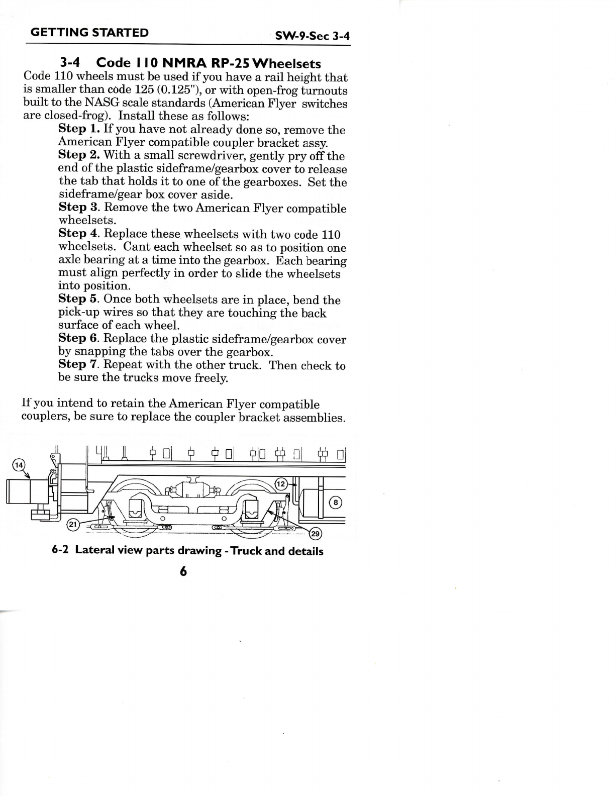
3-4
Code
I
10
NMRA
RP-25
Wheelsets
Code
110
wheelsmust
be
used
ifyou
have
a
railheight
that
is
smaller
than
code
125
(0.125"),
or
with
open-frog
turnouts
built
tothe
NASG
scalestandards(AmericanFlyerswitches
are
closed-frog).
Installthese
as
follows:
Step
1.Ifyou
have
not
alreadydone
so,
remove
the
American
Flyercompatiblecouplerbracketassy.
Step
2.
With
a
smallscrewdriver,gently
pry
off
the
endofthe
plasticsideframe/gearboxcover
to
release
thetab
that
holds
ittoone
of
the
gearboxes.
Setthe
sideframe/gear
box
cover
aside.
Step
3.
Remove
the two
AmericanFlyercompatible
wheelsets.
Step
4.
Replace
these
wheelsetswith
two
code
110
wheelsets.Canteachwheelset
soasto
position
one
axle
bearing
ata
timeinto
the
gearbox.Eachbearing
must
align
perfectly
in
order
to
slide
the
wheelsets
intoposition.
Step
5.
Oncebothwheelsets
arein
place,bend
the
pick-up
wires
so
that
they
are
touching
the
back
surface
of
each wheel.
Step
6.
Replace
the
plasticsideframe/gearbox
cover
by
snapping
the
tabsover
the
gearbox.
Step
7.
Repeatwith
the
othertruck.Thencheck
to
be
sure
the
trucks
move
freely.
If
you
intend
to
retain
the
AmericanFlyercompatible
couplers,
be
sure
to
replace
the
couplerbracketassemblies.
6-2
Lateral
viewpartsdrawing-Truck
and
details
6

GETTING
STARTEDSW-9-Sec
3-5
3-5
Alternate
AC
StartingDirection
Right
outofthe
box,your switcherwillalways
start
inthe
forward
(long
hood
in
front)
direction
ifithas
been
standing
for
more
than
30
seconds.However,
ifyou
wish
to
designate
thecabendas
"front"
(asyou
would
foroneoftwo
back-to-
back
units),
the
default
starting
direction
can be
reversed.
To
change
the
defaultdirection,remove
the
four
screws
that
hold
the
bodyassembly
tothe
chassis
and
lift
off
the
body.
You
will
find
a
smallsocket
just
behind
the
front
radiator
grille.(Thissocket
is
Part
No.16inthe
"cross-section
parts
drawing
-
gearbox
and
details"
on
page
11.)
In
this
socket
there
isa
slideswitchwhosepositiondetermines
the
default
locomotive
direction.
To
change
the
defaultdirection,simply
slide
the
toggle
tothe
oppositeside
ofthe
switch.Replace
the
body
onthe
chassis
and
secure
it
with
the
four
screws
(Do
not
overtighten).
Front
of
switcher
ooooooool
1
rp.
\3
•
10
1
2
3
4
11
OO
0000
0000
OO
9
8
7
6
5
12
Expanded
8 pin
NMRA
socket
(2:1)
6-3
Socketdiagrams
pin
I
2
3
4
9
II
function
motor(+/R)
light
-
rear
shorted
topin7
pick-up(L-fi
reman)
speaker
strobe
light
color
orange
yellow
-
black
purple
green
pin
5
6
7
8
10
12
function
motor(-/L)
light
-
front
light(common)
pick-up(R-engineer)
speaker
cab
light
color
gray
white
blue
red
purple
brown
6-4
Eight
Pin
NMRA
socket
Key
7

GETTING
STARTED
SW-9-Sec
3-6
3-6
DC
Polarity
Reversing
Options
WARNING:
Donotuse
this
feature
with
AC
current.
If
yourun
yourSW-9with
the
AC/DC
no
soundoption
on
a
layoutpowered
by DC,it
willoperateperfectly
and
cycle
reverse
the
same
asifit
werepowered
byAC.
Most
DC
layouts
useDC
polarity
to
reverse direction,however.
You
can
convertyourswitcher
toDC
polarityreversing.Access
the
reversingplug
by
following
the
instructions
inthe
previous
paragraph(Section3.5).Remove
the
factory-
installedplug
from
the
socket
and
replace
it
with
theDC
shortingplug,furnished
asa
separate
part
in
yourswitcher
packaging.
TwoDC
shortingplugs
are
provided,
one
with
thecab
light
onandthe
otherwith
thecab
light
off.
Once
the
plug
is
inserted,
setthe
body
onthe
chassis
and
test
the
locomotive.Replace
the
body
onthe
chassis
and
secure
it
with
the
four
screws
(Donot
overtighten).
3-7
AC/DC
LocoMatic™
Sound
Units
Another
optionavailable
for
yourswitcher
is
LocoMatic™
Control
withsound.Thisfeature
canbe
orderedfactory
installedwith
the
switcher,
or
purchased
later
for
installation
by
the
owner.Thisallows
the
unit
to
operatewith
ACor
DC
track
power
andis
different
from
mostother
LocoMatic™
systems.
It
does
not
contain
the DC
shift
for
operation
of
the
Horn
and
Bell.Therefore
it
requires
theuse
of
the
#00552
LocoMatic™
10
ButtonController
for
thesefunctions.
This
was
designed
forSHS
Inc.
by
DalleeElectronics,
Inc
andis
available
for
$69.95.
DC
operatorsshouldoperate
in
LocoMatic™
COMMAND
CONTROL
only.
If
operated
withvariable
DC
trackpower
in
standardmode,thennormal
AC
likesequencingwilloccur.
The
Horn
or
Bellwill
not
constantlyoperatingsince
the
decodingcircuitry
isnot
present
in
this
system.Conventional
AC
operation
follows
the
usualsequence
of
forward
-
neutral
-
reverse
-
neutral
-
forwardsequence
pattern
except
that
the
initial
state
is
switchselectable
for
either
start
in
forward
or
start
in
neutral.
A
locomotive
can
also
be
switchlocked
inthe
forward
8
GETTING
STARTED
SW-9-Sec
3-7
position
to
accomodateoperationunderautomatedsituations.
An
additional
direction
switch
is
provided
so
that
if
several
locomotives
arerunina
multiple
unit
lash-upsimply
set
this
switch
on
eachlocomotive
to
specify
whichdirection
is
forward,
engine.
Ifthe
direction
of
the
locomotive
is
opposite
of
that
desiredsuch
as
back
to
backoperation
as
commonly
seenwithswitchers.
SOUNDS
REPRODUCED
The
sounds
ofthe
switcherhavebeenrecorded
from
an
actual
locomotive
andare
prototypicallycorrect
for
utmost
realism.
HORN
is
useractivated
bythe
HORNbutton
ononthe
LOCOMATTC™
CONTROLLER.
The
hornwillplay
as
long
asthe
switch
or
button
is
held
on.
BELL
is
useractivated
bythe
BELLbutton
onthe
LOCOMATIC™
CONTROLLER.
The
BELLsoundwill
latch
"on"
when
the
bellcontrol
is
activated
and
willlatch "off
when
the
control
is
againactivated.
Any
BELLrequests
at
higherspeedswill
be
ingored.
The
BELL
canbe
activated
at
higher
speeds
if
requested
at
lowerspeeds
and
then
the
locomotive
speed
is
advanced.WhenBELLsound
is
requested,
the
soundsystemwillfirstadjust
the
diesel
sound
totheRPM
required
for
simultaneousplay.When
deactivating,
the
BELLwillstop
attheendofa
ring
and
the
dieselsoundwill
return
tothe
correct
throttle
setting.
BELL
sound
can
also
be
requestedwhendieselprimemover
sound
has
beenturned
"off1.
Again,
a
manualswitchallows
the
bell
tobe
deactivated
for
multipleunit(MU)operation.
AIR
SYSTEMRELEASE(POPS)
Airis
pumped
continuously
ina
diesellocomotive
to
maintainpressure
in
the
brakesystem
andfor
otherpurposes.Periodically,
accumulatedmoisture
and any
excesspressurewill
be
ventedthrough
a
releasevalve.These
AIR
RELEASEsounds
(pops)
are
generated
at
randomintervalsduringidle
and
atall
throttle
settings.
9
GETTING
STARTED
SW-9-Sec
3-7
BRAKE
RELEASEsound
is
producedwhen
the
locomotive
changes
from
neutral
toa
movementdirection
and
will
alwaysprecedelocomotivemovement.
PRIMEMOVER(Diesel)sounds
range
from
idle
to
full
RPM
witheight
throttle
notches.
In
neutral
or
with
no
power
tothe
motor
the
soundsystemwillproducediesel
engineidlesounds.When
a
movementdirection
is
selected
andthe
speedcontrol
is
advanced
toputthe
locomotive
in
motion,
a
brake
release
willsound(seeabove)
andthe
dieselsoundwill
initially
accelerate
to
about
throttle
notch
#4,
and
then
seek
the
correctnotch
setting
for
locomotive
speed.This
simulates
the
normaldelay
ona
diesel
locomotive
between
throttle
action
and
actual
movement.
Therewill
bea
distinctvolumeincreaseduringacceleration.
Soundvolumeshould
be
somewhatloweroncespeed
has
stabilized
and
should
be
reducedduringdeceleration.
Depressing
theALT/
FORWARD
button
onthe
LOCOMATIC
CONTROLLER
willdirect
the
soundsystem
to
accelerate
to
full
RPM
regardless
of
motorvoltage.
Depressing
theALT/
FORWARD
buttonagainwillrelease
the
soundsystem
to
return
tothe
correct
throttle
notch
setting.
Thisfeatureallows
the
simulation
ofa
heavy load
withveryslowlocomotivespeed
or
"pumpingair"
ina
standing
train.
LIGHTING
FEATURES
The
switcher
is
equippedwith
lighting
that
is
directional
so
that
the
headlight
will
illuminate
when
the
locomotive
isin
forwardmotion.When
the
locomotive
isin
reverse
motion
the
headlight
will
turn
off.
The
headlights
and
interior
cab
light
also
be
manuallyoperated
by
means
of
theSHS
#00552
LOCOMATIC™
CONTROLLER.
OPERATION
USING
ATRANSFORMER
With
this
sound
/
controlsysteminstalled,yourlocomotive
willoperate
inthe
samemanner
as
otherlocomotiveswhen
using
a
transformer
to
varyspeed.Whenpower
is
applied
the
locomotivewillcome"on"
in
either
the
forward
or
10
GETTING
STARTED
SW-9-Sec
3-7
neutralposition
asyou
haveselected.Momentary
interuptions
of
powerwillallow
the
locomotive
to
sequence
through
the
usualdirectionpositions.Sequencing
canbe
accomplished
either
bya
direction
switch/button
orby
turning
the
speedcontrol
to
"off
and
then
back"on".
An
added feature
of
this
sound
/
controlsysteminvolves
thewaythe
motor
is
driven,particularly
at
slowspeeds.
When
track
power
isat
lowervoltages
the
systemfurther
reduces
the
power
tothe
motor
soasto
provideextremely
smooth
slow
speeds
for
starting
and
stoppingyourtrain.
If
the
trackpowerfluctuates
at
theselowervoltages
you
may
notice
a
slight
surging
inthe
speed
ofthe
locomotive.
If
track
power
isset
highwhile
in
neutral
andyou
sequence
to
a
direction,
the
locomotivewillgraduallyincrease
its
speed
rather
than
jumpdirectly
tothe
highspeed.Thistype
of
operation
not
onlylooksbetter
but
also
results
in
less
strain
onthe
entiremotor
/
geardrivesystem
andis
less
likely
to
causederailments
ofthe
locomotive
orits
train.
SHS
#00552
LOCOMATIC™
CONTROL
Your
SHS
switcherwilloperatecorrectlywithyour
transformer
inthe
samemanner
as
traditionallocomotives,
but
with
the
simpleinstallation
ofthe
optional
LocoMatic
Control
Box,operationwill
be
greatlyenhanced.
The
LocoMaticControllercontains
ten
operating
buttons
and
is
usableeither
in
conjunctionwithyour regular
transformer
orasan
independentcontrolwith
a
fixed
voltage
applied
tothe
track.
The
LocoMatic
Controller
isa
pass
through
type
of
devicewhich
is
wiredbetweenyour
transformer
and the
track.
The
LocoMatic
Controlleritself
is
powered
bya 9
volt
DC
plug-inpowersupplywhich
is
included.
Some
ofthe
buttonscause activation
as
long
as
they
are
held"on"whileotherswork
ina
push-on,push-off
mode.
The
lower
right
handbutton,labled
'ALT',
isthe
alternatebuttonwhichprovides
a
second
function
to
each
of
the
otherninebuttons.
For
example;pressing
the
HORN
II
GETTING
STARTED
SW-9-Sec
3-7
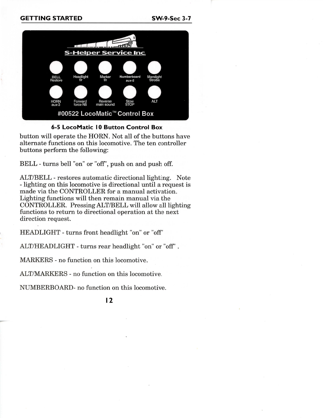
6-5
LocoMatic
10
ButtonControl
Box
button
willoperate
the
HORN.
Notallofthe
buttonshave
alternate
functions
on
this
locomotive.
Theten
controller
buttons
perform
the
following:
BELL
-
turnsbell"on"
or
"off',
push
onand
push
off.
ALT/BELL
-
restoresautomaticdirectionallighting.Note
-
lighting
on
this
locomotive
is
directionaluntil
a
request
is
made
viathe
CONTROLLER
fora
manualactivation.
Lighting
functions
willthenremainmanual
viathe
CONTROLLER.
Pressing
ALT/BELL
willallow
all
lighting
functions
to
return
to
directionaloperation
atthe
next
direction
request.
HEADLIGHT
-
turns
front
headlight"on"
or
"off
ALT/HEADLIGHT
-
turnsrearheadlight "on"
or
"off
.
MARKERS
- no
function
on
this
locomotive.
ALT/MARKERS
- no
function
on
this
locomotive.
NUMBERBOARD-
no
function
on
this
locomotive.
12

GETTING
STARTED
SW-9-Sec
3-7
ALT/NUMBERBORARD
-
turns
cab
light
"on"
and
"off.
MARSLIGHT/STROBE
- no
function
on
this
locomotive
ALT/STROBE
-
turns
strobe"on"
and
"off
HORN
-
activates
the
horn
ALT/HORN
- no
function
on
this
locomotive
FORWARD
-
forwardmotionoverriding sequencing
from
neutral
in
standardmode.Increasesspeed
in
command
mode
if
alreadyrunning
in
forward.
If
running
in
reverse,
speed
willdecreasethroughneutral
to
forward
depending
on
how
long
the
button
is
pressed.
ALT/FORWARD
-
this
forces
the
primemover
RPM
sound
to
full
speed(notch
8)
regardless
of
voltage
setting.
Use
this
to
simulate
pulling
heavy
drags,
pumping
upair
tanks
when
sitting
still,etc.Pressing
ALT/FORWARD
again
returns
RPM
sound
to
normal.
REVERSE
-
reversemotionoverridingsequencing
from
neutral
in
standardmode.Increasesspeed
in
command
mode
if
alreadyrunning
in
reverse.
If
running
in
forward,
speed
willincreasethroughneutral
to
reverse depending
on
how
long
the
button
is
pressed.
ALT/REVERSE
-
turns
OFF
mainsoundsleavingonly
the
Horn
and
Bell
if
selected
(only
the
horn
ifdip
switch
3 set
on).
Anotherpushwillrestore
the
mainsounds. Main
sounds
includebrakerelease,
air
pops
and
primemover.
SLOW
-
neutralposition overridingsequencing
toa
momentum
stop
- in
standardmode.Slowdown
a
step
per
push
of
button
in
commandmode.
ALT/SLOW
-
neutral
position
or
emergencystop.
13

GETTING
STARTED
SW-9-Sec
3-7
ALT
-
alternate
button
for
secondfunctions
of
other
9
buttons.
Must
be
helddown
in
conjunctionwith
one
otherbutton.
It
may
be
depressedfirst
and
heldwithout anotherbutton
leavingonly
one
otherbutton
to
press.
Notice:
Pressingmore
than
one
button,other
than
the
ALT,
produces
no
signal.
Itisan
invalidoperation.
INSTALLATIONOFTHE
LOCOMATIC™
CONTROLLER
Connect
two
wires
from
yourtransformer
tothe
terminals
on
the
CONTROLLER
labeledTrans,
IN.The
"B"
terminal
is
the
base
andthe
"16"
terminal
isthe
"hot".Thenconnect
two
wires
from
the
terminalslabeledTrack
OUTtothe
track.
The"B"
terminal
is
connected
tothe
inside
rails
of
your
track
andthe
"16"
is
connected
tothe
outer
rail.
This
installs
the
CONTROLLER
asa
passthroughbetweenyour
transformer
andthe
track.
We
recommendusing
#20
strandedwire,
asa
minimum,
for
these
connections.
Ifthe
CONTROLLER
isnot
"on",your transformerwill
still
function
normally.Connect
the9
volt
DC
powersupply
to
the
inputjack
onthe
CONTROLLER
and
plug
itin.The
CONTROLLER
isnow
"on"
andis
ready
to
operatewith
your
transformer.
In
summary,LocoMaticControlallowsfingertipoperation
of
a
uniquesound
and
controlsystemwith
the
additional
features
of
realistic,prototypicalspeed
and
directioncontrol.
Right
out
of
the
box,yourswitcherwillalways
start
inthe
forward
direction
ifithas
been
standing
for
more
than
30
trans,
tra
INOU
15
B
15
nnnn
I
,
FROM
•
TRANSFORMER
TO
TRACK
TO
9
VOLT
TRANSFORMER
6-6
LocoMaticControllerwiring
14

GETTING
STARTED
SW-9-Sec
3-5
seconds.
However,
ifyou
wish
to
designate
the
rear
endas
"front"
the
default
starting
direction
canbe
changed.
DIP
SWITCH
OPTIONS
-
MANUAL
ADJUSTMENTS
The
exhauststacksection
canbe
removed
to
reveal
the
LocoMatic
Soundunit.Grip
oneofthe
exhauststackswith
your
thumb
and
finger,
and
pull
straight
out.
It
just
snaps
in
place.There
are
four
dip
switches
anda
volumecontrol
on
the
smallcircuitboard.
The
soundpotentiometer
is
factory
setata mid
range
(12
o'clock).
Rotating
this
control
counter-clockwise
willincrease
the
volume.
Itis
suggested
that
the
volumecontrol
besetat
about
the
middle
of
its
range
for
comfortablelistening.
The
four
dip
switches
are
normally
settothe
"offposition
and
select
the
following
operations:
OFF
#
1
start
in
forward
#
2
sequencingnormal
#
3
bell
can
sound
#
4
forwarddirection
is
ON
neutral
lock
in
start
does
not
sound
front
rear
OFF-
-ON
-»•
m
i
Switches
3&4 are
usedprimarily
when
two or
morelocomotives
are
operatedtogether.
Youcan
turn
off
the
bell
inthe
trailing
locomotives.
Ifanyofthe
locomotives
are
actuallyfacing
to
the
rear,Switch
4 on
such
locomotives
allowsoperation
in
concert
withotherlocomotives
facing
forward.
When Switch
4
changes
forward
to
rear,
all
directionalfunctionssuch
as
5.7
p|p
Switches
headlights
are
switchedalso.
(enlarged)
3-7
DCC
(Digital
Command
Control)
A
DigitalCommandControl
(DCC)
decoder
isnot
included
withyourswitcher.However,yourlocomotivecomes
factory-
ready
to
receive
a DCC
decoderwithoutmodification*.
15

GETTING
STARTEDSW-9-Sec
3-7
Purchase
a DCC
decoder
from
a
vendor
of
yourchoice.
We
recommend
purchasing
a 1.0to2.0amp
decoder.
To
install
your
DCC
decoder,expose
the
reversing-plug
socket
by
following
the
instructions
in
Section
3.5.
Remove
the
factory-
installedprintedcircuitboard
(ortheDC
shortingplug)
and
plugyour
DCC
decoderinto
the
socket.Many
DCC
manufactures
offer
the
NMRA
mediumplug.
Factoryinstalled"Tsunami"
DCC
Sounddecoders
by
Soundtraxx
are
available.Thoseswitcherscomewith
an
additionalinstructionbooklet
on
their
operation
and
installation.
*
DCC
Installation
Note:
If
yourswitcher
hasa DCC
warninglabelattached
tothe
socketprintedcircuitboard,
it was not
wired
to the
NMRA
standards
and
willneed
to
be
replaced
for DCC
operation. Replacementsockets
are
available.Pleasecontact
SHS
regarding
our
replacement
program.
SECTION
4 -
Maintenance
4-1
Lubrication
Your
new
switcherdieselswitchercomesfactorylubricated
and
ready
forthe
break-inperiod.
After
break-in,
we
recommend
inspection
and
carefullubrication
ofthe
wheel
bearings.With
the
modelupsidedown,place
a
smalldrop
of
Aero
Lube"ConductaLube"
on
eachaxlenext
to
each
of
itstwo
bronzebushings
andthe
back
ofthe
wheels.
Use
only
a
drop,overlubrication
can
damage
the
body
as
well
as
void
the
warranty.
4-2
Golden
White
LEDs
The
LEDs
in
yourswitcher
are
rated
at3.5
volts
and30
milliamps
for
maximum
life
and
should
not
need
tobe
replaced. But,
just
in
case:
Step
1.
Remove
the
four
screws
that
hold
the
body
assembly
tothe
frame
and
lift
off
the
body.
Step
2.
Unplug
the
AC/DC
circuitboard.
Step
3.
Before
removing
LED
printedcircuitboard,
16

MAINTENANCE
SW-9-Sec
4-2
note
the
position
ofthe
wires
and
coppercontacts.
Rear
LEDs
(Steps
4-7):
Step
4.
Push
the
rear
LED
contactwires(brass)
to
the
side
Step
5.
With
a
smallflat-bladescrewdriver,release
thetab
below
thecab
sidewindows
and
remove
the
cab
floor.
Step
6.
Remove
theLED
circuitboardbracket
by
unscrewing
thetwo
phillips-head
screws.Gently
pull
the
contactwires
from
the
tabs
onthecab
roof
and
unsolder
thetwo
rear
bulbleads.
Step
7.
Solder
a newLED
circuitboardintoplace
and
attach
the
rear
LED
bracket.
Push
the
contact
wires
backinto
the
tabs
and
position
and
replace
the
cab
floor.
Re-install
cab
onto
the
body,
bend
the
contactwires
up,and
replace
rear
LED
wires
into
thesix
body
tabs.
Step
8.
Remove
the
front
LED
bracket
by
unscrewing
thetwo
phillips-head
screws.Replacewith
a new
LED
pcb
assembly
and
solder
in
place.Then
re-
attach
the
front
LED
bracket.
Step
9.
Re-insert
the
AC/DC
circuit-boardplug
(if
used)
into
its
socket.Thenre-attach
the
body
assembly
tothe
frame
(Donot
overtighten
screws).
4-3
Cleaning
Body
-
Removedustwith
a
small
soft
brush
(make-up
brush
or
similar).
If
yourswitcherrequiresmoreextensivecleaning,
we
recommendremoving
the
body
from
the
chassis
and
cleaning
the
body
with
dishwashing
detergent
anda
small
sponge.
Rinse withcleanwater(makingsure
nottoget
waterinto
the
interior
ofthe
cab)
and
blot
or
blow
dry
with
low
heat.
Pilots
canbe
removed
from
the
chassis
and
cleaned
inthe
sameway.
Wheels
-
Dirtwillbuild
up on the
wheeltreadsovertime.
To
remove
this
and
improvetraction
and
electricalpick-up,
we
recommendusing
91%
isopropalalcohol
anda
Q-tip.
17

MAINTENANCE
SW-9-Sec
4-3
Again,
remove
the
body
from
the
chassis,
asthe
alcohol
can
damage
the
body
finish.
Rub
eachwheeltreadwith
the
alcohol-moistened
Q-tip,applyingslightpressure
to
remove
the
dirtbuild-up.
The
wheels
canbe
rotated
by
hand-
turning
theflywheel.
Once
the
wheels'treads
are
clean,
check
the
electricalpick-upwipers
for
cleanliness
andfor
contact
against
the
insidesurfaces
ofthe
wheels.
Storage
-
Wheneveryourswitcher
is
withdrawn
from
service
for
an
extendedperiod,
we
suggest
you
store
itinits
original
foam
tray
and
gift
boxfor
maximumprotection.
4-4
Pick-upwipersreplacement
Step
1.
Using
a
smallscrewdriver,gently
pry
loose
theendofthe
plastic
sideframe/gearbox
cover
to
release
thetab
that
holds
ittothe
gearbox.
Step
2.
Remove
thetwo
wheelsets.
Step
3.
Remove
the
pick-up
wipers'bracketscrew.
Thenremove
the
worn pick-upwipers.
Step
4.
Replace
the
wornpick-upwiperswith
new
ones
and
reinstall
the
pick-upwipers'bracketscrew.
Step
5.
Re-insert
the
wheelsets.Note
that
the
bearingsmustalign
perfectly
forthe
wheelsets
to
slideinto
the
gearbox.
Step
6.
Oncebothwheelsets
arein
place,check
that
the
pick-up
wipers
areall
contacting
the
inside
surface
of
the
drivers.
Step
7.
Replace
the
plastic
sideframe/gearbox
cover
by
snapping
the
tabs
over
the
gearbox.
Step
8.
Check
tobe
sure
the
trucks
move
freely.
4-5
Heavy
Duty
Lubrication
If
yourswitcheroperates
ona
clublayout,
at
shows,
or
receives
unusuallyheavyusage,
the
worm
and
idlergears
will
needperiodiclubrication
to
preventexcessivewear.
To
lubricatetheseareasmost
effectively,
completedisassembly
of
the
gearbox
is
necessary.
Step
1.
Remove
the
four
screws
that
hold
the
body
assembly
tothe
frame
and
lift
off
the
body.
18

MAINTENANCE
SW-9-Sec
4-5
Step
2.
Unplug
the
AC/DC
circuitboard
(if
you
are
not
using
DC
polarity
reversing
or
DCC)
andthetwo
forward
and
reverse lightplugs.
Step
3.
Remove
the
AmericanFlyercompatible
coupler
bracket
andthe
four
wheelsets.(See
Code
110
NMRARP
25
ContourWheelsets,Section4.4.)
Step
4.
Remove
the
e-clips
that
hold
the
gearbox
to
the
geartower
and
lower
the
gear
box
from
the
chassis.
Step
5.
Remove
the
plasticpick-upwiperassembly,
taking
care
notto
break
the
wipers.Note
on
which
side
ofthe
gearboxeachbelongs.
Step
6.
Remove
thetwo
screwsholding
thetwo
halves
of
the
gearboxtogether.Once
the
gearbox
is
apart,
clean
theold
grease
from
the
gears
and
worm.
Lubricate
the
wormwith
ACT
gearLube
andthe
idlergearswith
ACT
motorbearinglube.
Step
7.
Re-assemble
the
gearbox
(Donot
overtighten
screws)
and
plasticpick-upwire
assembly.Carefullyre-connect
the
universaldrive
shaft
tothe
geartower
and
push
the
e-clip
backonto
the
gearbox stem.
Step
8.
Re-insert
the
AC/DC
circuitboardpluginto
6-8
Crosssectionpartsdrawing
-
gear
boxand
details
19
This manual suits for next models
2
Table of contents
Popular Toy manuals by other brands

Learning Resources
Learning Resources GEARS! MOTORIZED Wacky Wigglers Building Set instructions

twinkl
twinkl Foil Sparklers quick start guide

Horizon Hobby
Horizon Hobby Hangar 9 Spitfire 60 ARF Assembly manual

Comet
Comet 33206 instruction manual

LEGO
LEGO technic 8110 instructions

VERTBAUDET
VERTBAUDET Sirius 010855 manual

John Adams
John Adams Silly Sausage instructions

E-FLITE
E-FLITE Habu 32 EDF ARF instruction manual

Fisher-Price
Fisher-Price L3244 instructions

marklin
marklin 37735 user manual

Tiger Electronics
Tiger Electronics Alien Blaster 64-008 instructions

Ready 2 Folo
Ready 2 Folo The Party Stadium Assembly instructions


