S.R.Smith TURBOTWISTER Instruction manual

06-693 S.R. SMITH, LLC 2008 JULY 09
TURBOTWISTER
™
CORPORATE HEADQUARTERS
WESTERN SALES AND MANUFACTURING PLANT
P.O. Box 400 •
••
•1017 SW Berg Parkway
Canby, Oregon 97013
Phone: (503) 266-2231 •
••
•Fax: (503) 266-4334
www.srsmith.com
ASSEMBLY AND INSTALLATION
INSTRUCTIONS

2
Table of Contents
Topic Page #
Introduction………………………………………………………………………………………… 2
Parts List……………………………………………………………………………………………. 3
Assembly Instructions…………………………………………………………………………….. 4
Manufacturer’s Placement Instructions…………………………………………………………. 11
Installed Slides’ Structural & Installation Checklist…………………………………………….. 13
INTRODUCTION
THE TURBOTWISTER
TM
SLIDE IS DESIGNED AND MANUFACTURED FOR INSTALLATION AND
USE ON INGROUND SWIMMING POOLS ONLY. TURBOTWISTER
TM
SLIDES ARE NEVER TO BE
INSTALLED AND USED ON HOUSEBOATS, BOAT DOCKS, FLOATING DOCKS OR PLATFORMS,
OR OTHER BODIES OF WATER SUCH AS LAKES, PONDS, RIVERS, ETC. PROPER AND
COMPLETE ASSEMBLY, USE AND SUPERVISION IS ESSENTIAL FOR PROPER OPERATION AND
TO REDUCE THE RISK OF ACCIDENT OR INJURY.
**IMPORTANT**
Check entire boxes and inside all packing materials for parts. Before beginning assembly, read the
instructions and identify parts using the figures and parts listed in this document. It is critical that all
parts be carefully inspected by the installer prior to installation to ensure that no damage occurred in
transit and that a damaged part is not used. Proper installation cannot be overstressed, as an improper
installation voids S.R. Smith’s warranty and may affect the safety of the user.
FIG. 1
Left curve shown for illustration -
Right curve is a mirror image of the left.

3
(1)
(9
)
TURBOTWISTER
™
PARTS LIST
ITEM # PART # DESCRIPTION QTY.
1 5-139 3/8” Hex Nut 16 ea.
2 5-151 3/8” Lock Washer 16 ea.
3 05-14-115 1/2" Lock Washer 8 ea.
4 5-145 3/8” Flat Washer 37 ea.
5 5-235 3/8” x 2-1/4” Carriage Bolt 2 ea.
6 5-236 3/8” x 2-1/4” Button Head Cap Screw 2 ea.
7 5-249 3/8” x 3-1/4” Button Head Cap Screw 4 ea.
8 5-239 3/8” x 2-1/2” Stud 4 ea.
9 5-240 3/8” x 3-1/2” Lag Screw 9 ea.
10 5-237 3/8” x 5” Button Head Cap Screw 4 ea.
11 5-238 3/8” x 6” Hex Head Cap Screw 4 ea.
12 5-242 #14" x 1” Pan Head Tapping Screw 6 ea.
13 5-241 1/2" x 5” Anchor Stud 8 ea.
14 05-787 2” PVC Pipe Strap 2 ea.
15 05-788 1-1/2” Pipe Clamp 2 ea.
16 05-789-1 1.5” PVC Flex Hose, 6’ Length 1 ea.
17 05-789-2 1.5” PVC Flex Hose,15” Length 1 ea.
18 05-777 1.5” Ball Valve 1 ea.
19 05-781 1-1/2” Coupling 1 ea.
20 05-780 1-1/2” x 3/4” Reducer 1 ea.
21 05-779 Garden Hose Adapter 1 ea.
22 8-532 .5" High X .5” Wide X 32” Long Rubber Gasket 1 ea.
23 8-531 .25” High X .375” Wide X 33” Long Rubber Gasket 1 ea.
(2)
(3)
(5)
(6)
(8
)
(10
)
(11
)
(1
8
)
(13
)
(14
)
(16)
(17
)
(4)
(1
2
)
(19) (20)
(21
)
(
7
)
(22
)
(23
)
(15
)

4
.25” X .375”
GASKET
ASSEMBLY INSTRUCTIONS
Tools Required:
1. Ratchet handle
2. 9/16” deep socket
3. 9/16” wrench
4. 3/4" socket or wrench
5. 7/32” allen wrench
6. Phillips head screwdriver
7. 1/2" concrete drill bit
8. 1/4" drill bit
9. Power drill
10. PVC pipe primer & glue
11. Anti-seize
12. Saw to cut PVC pipe
13. Knife
14. Level
Gasket Installation:
•The gasket material has been installed at the factory, however additional gasket has been provided
in case any gasket has fallen off during shipping. If gasket installation is required, follow the instructions
below.
•Apply gasket in the required locations as shown in the figures below.
•Place gasket along the section to determine the length needed.
•Cut gasket to appropriate length.
•Remove backing and adhere gasket to slide.
•Gasket is applied to the ladder part face as shown below. All other gaskets are applied as shown
in the gasket section detail.
.5” X .5” GASKET
.5” X .5” GASKET
.5” X .5” GASKET

5
Assembly:
1. Place the pedestal on the
ground and set the exit slide
section on top.
2. Attach the exit slide section to
the middle slide section using the
hardware shown. If necessary lift
up on the exit end to keep the
joint tight while fastening.
Note: Ensure gasket material
at the joint is intact before
assembling.
NOTE: When assembling the
slide, apply a thin even coating
of anti-seize to all stainless
steel fasteners. Anti-Seize
helps aid in assembly,
prevents galling, and improves
corrosion resistance. Anti-
Seize can be purchased at
most auto parts stores.
(
10
)
(
1
)
(
4
)
(2)

6
4. Attach the pedestal to the
middle and exit slide sections as
shown in (3) locations.
3. Remove the assembled exit
and middle slide sections from
the pedestal. Turn over and
fasten from the underside as
shown.
5. Install the 3/8” studs into the threaded
inserts in the top of the ladder as shown in
(4) locations.
(11)
(4)
(1)
(2)
(8)
(9) (4)

7
(1)
(4)
(2)
(4) (7)
(6)(4)
(1
)
(2
)
(4)
(5)
7. Lay the ladder flat and attach the top
slide section as shown. Use the appropriate
hardware in 4 places. Note: Use caution
not to scratch the ladder during this
step!
6. Assemble the top and
bottom ladder sections
as shown. Install
hardware in the
appropriate locations but
do not fully tighten. This
will help aid in
alignment. Once all
hardware is in place,
fully tighten.
8. Stand the ladder upright and
assemble the slide components as
shown. Fasten from each side of the
slide runway first, then from the
underside.
Note: Ensure gasket material at the
joint is intact before assembling.
(11)
(4)
(2)
(1)
(10
)
(
4
)
(
2
)
(
1
)
(1
)
(2
)
(4)
(7)

8
9. Attach the base unit as shown in (6)
locations. Mark and drill a ¼” pilot hole
in the center of each recess before
fastening with the lag screws.
10. Assembly of Water Supply Plumbing Parts:
•Assemble parts as shown in Step “A” without glue. Place plumbing
assembly in slide ladder to check fit before proceeding.
•Mark alignment of parts with a pencil before disassembling. This will
aid in reassembling parts when gluing.
•Use PVC primer and glue to assemble plumbing parts as shown in
Step “A” above.
•Glue assembled water supply pipe to the 1.5” PVC fitting installed in
the ladder as shown in Step “B”.
•Secure the hose assembly in the ladder in (4) locations with the
hardware as shown in Step “B”.
(17)
(18)
(16)
(15)
(12)
A. B.
(4)
(9)
(14)

9
PLUMBING INSTRUCTIONS
1. The TurboTwister is designed for a water
supply line of 1-1/2” pipe. Plumb from pool
return line with a 1-1/2” PVC pipe “stubbed up”
at the deck positioned at the base of the
ladder. Refer to FIG. 1 on page 2. FIG. 1 is for
reference only. Assembled slide should be
placed in its correct location and the “stub up”
location marked and installed before mounting
the slide to the deck. “Stub up” should be dark
grey PVC to match the plumbing assembly of
the slide. Note: “Stub up” should extend
above the deck 18” in height. It can be cut
to proper length further in the installation
process.
2. If a garden hose is to be used, a garden hose
adapter fitting is included with the slide.
Assemble the pieces as shown and attach to
the end of the PVC plumbing assembly at the
base of the ladder.
3. Proceed to the following section for ON-DECK MOUNTING. After the slide has been mounted to
the deck, attach the “stub up” as necessary to the plumbing assembly installed in the ladder.
4. The TurboTwister can handle 25-30 gallons per minute. Water flow is to be regulated using the ball
valve near the base of the ladder.
“Stub up” location
(21)
(20)
(19)
Garden Hose
Adapter
Fittings
‘or’

10
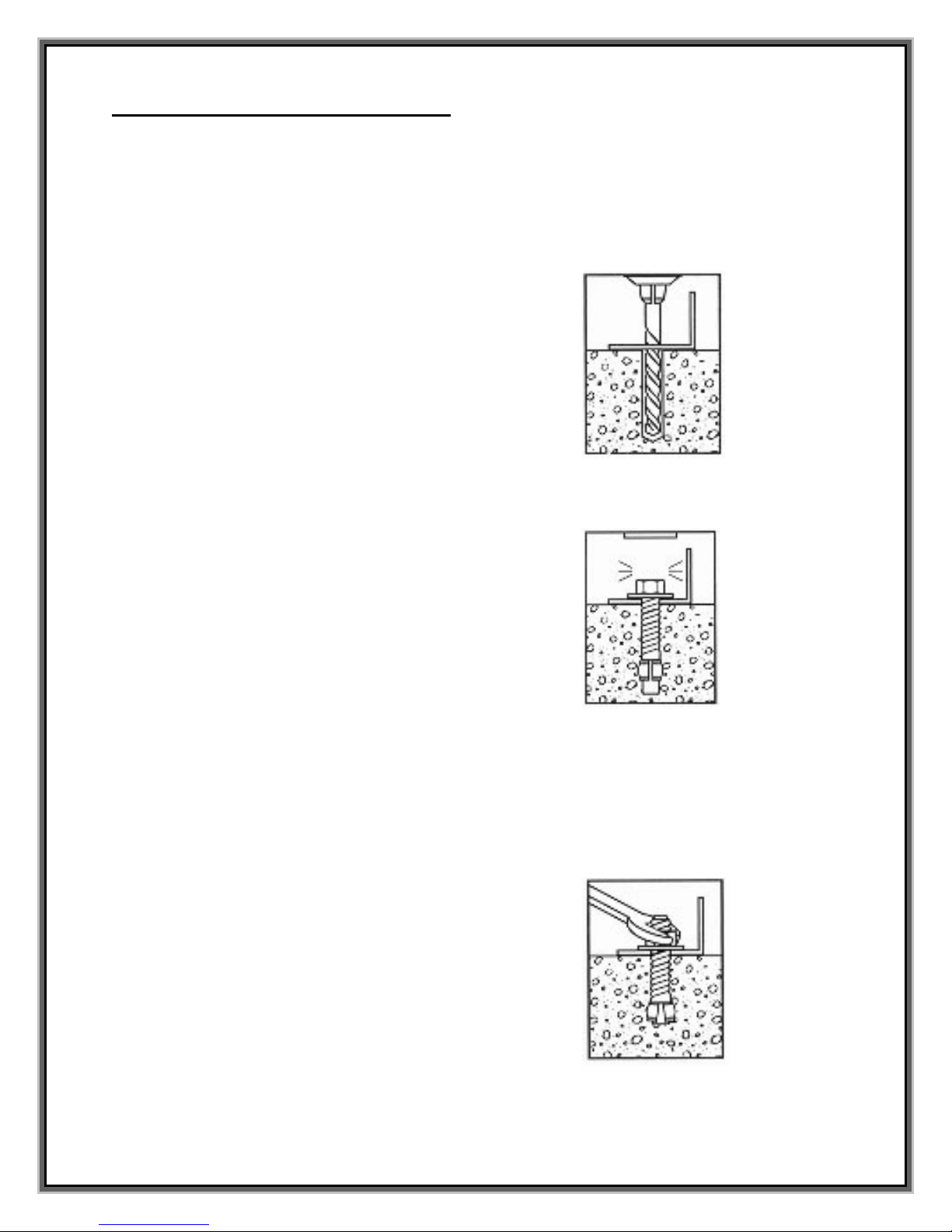
ON-DECK MOUNTING INSTRUCTIONS
1. Place the assembled slide on the deck relative to the pool wall. Ensure that the exit flume clears
any coping. Slide may be angled slightly providing all dimensions are maintained as noted in the
Manufacturer’s Placement Instructions noted in the following section.
2. With the slide in its proper location, center punch or otherwise mark through the (8) mounting holes
at the bottom of the ladder and pedestal so that a visible mark is apparent on the concrete.
3. Move the assembled slide aside to facilitate drilling of the
anchoring holes.
4. Using a power drill and a 1/2” concrete drill bit, drill the holes
to a depth of 4”. Use tape or a marking on the drill bit to
ensure that the hole for the anchor is drilled to the required
depth. Maintain drill hole straight and perpendicular for
proper holding strength of anchor stud.
5. Clear the holes of all debris. Assemble anchor with nut and
washer so that the top of the nut is flush with the top of the
anchor. Move the slide over the holes and insert the
anchors. Drive anchor through the slide mounting holes so
that nut and washer are flush with the surface material.
6. Ensure the slide ladder is plumb by placing a level on a ladder tread. If necessary, shims can be
provided by S.R. Smith to place beneath the base of the ladder to ensure it is plumb due to varying
deck slopes. Please call 1. 800.824.4387 if shims are needed.
7. Expand anchor by tightening nut 3 to 5 turns. Once anchor
is set remove nut and install a lock washer, item # (3), and
retighten nut to a torque of 25 ft.-lbs.

11
MANUFACTURER’S PLACEMENT INSTRUCTIONS
1. The critical dimensions for placement of the TURBOTWISTER
TM
are as shown in FIG.’S 8 and 9.
A. The slide exit runway surface shall not exceed twenty inches (20”) above the water surface as
shown in FIG. 8.
B. The slide shall be positioned so that all water flowing off the runway exit drops into the pool. The
recommended overhang is 4 inches.
C. The minimum depth of water below the exit lip of the slide shall be three feet (3’) and increase to
four feet six inches (4’-6”) at Pt. A, which is a distance of four feet six inches (4’-6”) from the exit
lip of the slide as shown in FIG. 8.
D. A minimum depth of four feet six inches (4’-6”) shall be maintained at a distance of nine feet (9’)
along the extended centerline of the slide from Pt. A. as shown in FIG. 8.
2. A minimum clearance area in front of the slide shall be maintained at all times as follows:
A. The minimum clearance distance on either side of the extended centerline of the slide runway
shall not be less than three feet six inches (3’-6”) at a point no less than
two feet six inches (2’-6”) from the exit lip of the slide and extending a
distance of thirteen feet six inches (13’-6”) in front of the slide as shown
in FIG. 9.
B. The minimum clearance area in front of a properly installed diving board
on an inground swimming pool is a minimum distance of three feet six
inches (3’-6”) on either side of the board’s centerline as shown in FIG.
10. Pt. C extends a minimum distance of “C” from the tip end of the
board as shown in FIG. 10. The width distance “W” on either side of Pt.
C is given in CHART 1 and shown in FIG. 10.
FIG. 8
FIG. 9
DECK/COPING SURFACE
3' MIN.
EXIT
RUNWAY SURFACE
PLUMBLINE
20" MAX.
WATER LEVEL
ENTRANCE
Pt.A
13'-6" MIN.
9' MIN. 4'-6"
4'-6" MIN.4'-6" MIN.

12
“C”
DIMENSION FOR BOARD
= AB + BC
“W”
DIMENSION FOR BOARD
= WIDTH AT PT.C
C. The minimum clearance area of a slide or diving board shall not intersect any coping or rope and
float line as shown in FIG. 11. The minimum clearance area of a slide or diving board may
intersect each other provided that they are not used simultaneously.
CHART 1
BOARD MINIMUM CLEARANCE AREA
POOL TYPE
“C” DIMENSION “W” DIMENSION
I 14’-6” 5’-0”
II 14’-6” 6’-0”
III 16’-6” 6’-0”
IV 18’-6” 7’-6”
V 21’-0” 7’-6”
See Article 5 contained in ANSI/NSPI-5 2003 STANDARD
FOR RESIDENTIAL INGROUND SWIMMING POOLS and
refer to FIGURE 3 and Table 1 for Minimum Water Envelope
Dimensions AB, BC and Width at Point C.
FIG. 11
FIG. 10

13
INSTALLED TURBOTWISTER
TM
STRUCTURAL & INSTALLATION
CHECKLIST
1. Inspect the runway for visible cracks or tears.
2. Inspect the slide for sharp edges, protrusions, cracks or tears.
3. Inspect all fasteners to make sure they are fully tightened.
4. Inspect the ladder for rigidity and attachment.
5. Measure the following dimensions and compare with the Manufacturer’s Placement Instructions
on pages 11 and 12.
•Measure the depth of water in front of the slide exit. (4’-6” min. depth at a distance of 4’-
6” from exit end of slide.)
•Measure the height of the slide runway exit above the water. (20” max.)
•Measure the distance between the slide centerline and the edge of other pool equipment.
6. Observe the position of the exit of the slide as shown in FIG.’S 8, 9 and 11 on pages 11 and 12.
IMPORTANT
PERSONALLY GIVE TO SLIDE OWNER THE TURBOTWISTER
TM
OWNER’S
MANUAL, THE WARRANTY CARD AND ANSWER ALL QUESTIONS.
Other manuals for TURBOTWISTER
2
Table of contents
Popular Accessories manuals by other brands

Air Creative
Air Creative Classic Line 925 installation guide

texet
texet PB2000 instruction manual

Girard Systems
Girard Systems GG750 Service and repair manual

Rogers
Rogers Glass Break Sensor installation guide

La Crosse Technology
La Crosse Technology TX12U instruction manual

BASETech
BASETech 1710064 operating instructions