S-Tech SV User manual

P a g e . 1 | 15
TECHNICAL MANUAL
Instructions for installation and commissioning of seismic
valves model: SV
English version

P a g e . 2 | 15
INDE
1.General information and warnings for installer staff (page.3)
2.Prescriptions before installation (pag.4)
3.Safety instruction (Pag.5/6)
4.Instructions for installation, use and maintenance of the valve SV (pag.7/8)
5.Commisioning and maintenance (page.9)
6.Reset and activation of the device (pag.10/11)
7.Information indicated on the product (pag. 12)
8.Declaration of conformity CE (pag. 13)
9.Warranty (pag. 14)
10. Contacts (pag. 15)

P a g e . 3 | 15
Before to proceed to installation, commissioning or
maintenance, operators must:
• Examine the safety provisions applicable to installation which they must operate;
• Obtain the necessary permits to operate when required;
• Adopt the necessary personal protection equipment.
• Ensure that the area in which they operate is equipped both with means of collective
protection provided and the necessary security details; in particular if
the gas used is flammable the surrounding area must be ATE classified.
•In particular, check if the area in which you work is classified for ATE purposes and
corresponding to the product marking (2G = Zone 1)
PRELIMMINARY CHECKS FOR PROPER OPERATION
It is advisable to execute a preliminary verify of product at the time of delivery for detect and report any damage
incurred during transport and handling. In the event of a claim you should contact our technical assistance office.
GENERAL PRODUCT INFORMATION:
-TECH is a trademark owned by Gas Broker srl used for the marking and distribution of seismic valves model V. The
use of gas valves with automatic seismic action with manual reset is recommended, and it is also, in some cases, a
legal obligation, to prevent damage caused by an earthquake from adding other damage due to fire or explosion
caused by the consequent gas leaks.
The valves have been designed to automatically intercept the gas in the event of an earthquake according to the
internationally recognized American standard A CE 25-16 and have been subjected to the CE marking according to
the following European directives:
DIRECTIVE 2014/34 / EU (ATEX) in force since 20/4/2016 concerning the approximation of the laws of the
Member tates relating to equipment and protective systems intended for use in potentially explosive
atmospheres.
DIRECTIVE 99/92 / EC OF THE EUROPEAN PARLIAMENT AND OF THE COUNCIL of 16 December 1999
relating to the minimum requirements for improving the protection of the safety and health of workers who
may be exposed to the risk of explosive atmospheres.
DIRECTIVE 2014/68 / EU (PED) implemented with Legislative Decree 26/2016 for the approximation of the
laws of the Member tates on pressure equipment.
For the purposes of preventing seismic risks and identifying seismic areas, the Presidency of the Council of Ministers
issued on 20 March 2003, ordinance N ° 3274, updated with OPCM 3519/06, which provides that they are used as
reference standards some technical guides attached to the ordinance, drawn up by experts in the sector.
ome data on seismic risk can also be obtained from the civil protection site:
https://rischi.protezionecivile.gov.it/it/sismico/attivita/classificazione-sismica
Once your seismic area has been identified, even if there is no legal obligation (... service systems above 50 m3 / h
must be equipped with valves for the automatic interruption of the gas supply...), therefore also for systems with a
flow rate of less than 50 m3 / h including domestic, it is recommended to install the seismic valve in order to avoid
further dangerous situations in the event of an earthquake.
V valves have sizes ranging from DN15 up to DN250 with two pressure classes 500mbar and 4bar as prescribed by
the Asce25-16 technical standard and can be installed vertically or horizontally.
For the European market, the product is distributed with the CE marking while for markets in the Americas the valves
are subjected to the C A (U + C) marking; both markings are evaluated by the third Notified Body for compliance
with the Axes 25-16 technical standard.

P a g e . 4 | 15
PRESCRIPTION BEFORE INSTALLATION
The device consists of a valve with a mechanical seismic actuator, with automatic intervention, with manual reset,
which can be installed, depending on the project, in a vertical or horizontal position. In its normal working position,
the valve is armed in the open position and closes automatically by releasing the shutter when the mechanical
seismic actuator detects stresses like those indicated in the Axes 25-16 technical standard.
The V valve is designed for installation upstream of the gas system that develops inside both civil and industrial
buildings or near the regulation and measurement units to protect them or, in any case, to protect the section of the
plant, utilities or equipment located downstream of the V seismic valve in the case of seismic events or catastrophic
damage that can stress the valve like the magnitude of an earthquake (accidental violent shocks, landslides, violent
floods, etc.).
Before proceeding with the assembly, it must be ensured that the V seismic valve to be installed is suitable for the
place in which it will be used both for the presence of an area classified as dangerous for explosion and for the
pressure rating of the piping.
The utmost care must be used during loading, unloading, transport and installation operations in order to safeguard
the integrity of all parts of the V valve.
V valves must always be used within the standard installation conditions provided by the manufacturer.
For the installation of the V valve, the environmental conditions must be taken into account to ensure correct
operation over time. The manual reset element of the valve, the bubble viewer that indicates the correct installation
position and the plate should be easily accessible to operators in charge of operation and maintenance.
Any subsidence / settlement of the ground, corrosion and other risks must be taken into account. The components
used for installation must be suitable for the pressures and temperatures that occur under normal operating
conditions as well as for pressures up to the declared Maximum Operating Pressure. For any arrangements inside
buildings, the fire protection names contained in EN 1775 must be respected.
The installation, use and maintenance of the V valve in a different way from that foreseen by the manufacturer (see
the standard installation conditions and the prescriptions given below) can jeopardize the protection method
adopted due to the risk of explosion (with very serious consequences for safety) and the annulment of the EC
declaration of conformity, thus invalidating the respective responsibilities on the part of the manufacturer.
The same consequence occurs if modifications of any kind are made to the valve or if it is modified or disassembled
having access to the internal parts without authorization or if it is used improperly that does not comply with what is
described in this manual.
However, the possibility of using the V valve in installation conditions other than those indicated is not excluded,
unless verified by the manufacturer, but in any case it can only take place with the specific written authorization of
the manufacturer.
Requirements for technical staff
Installation and maintenance must be carried out by suitably trained personnel with proven experience and in
compliance with the applicable European directives and local regulations and must be carried out by personnel with
the qualifications required by Italian law for installation and maintenance. of plants and equipment that use
combustible gas.
During these activities, personnel not strictly necessary must be removed and the work space must be appropriately
marked, which must highlight the dangerous conditions, prohibitions, behaviors and safety information in
accordance with current workplace safety regulations.

P a g e . 5 | 15
SAFETY INSTRUCTION
SV seismic valves must be used in compliance with the following requirements which are essential for protection
against the risk of explosion.
Before starting the installation, in agreement with the customer's safety managers, it must be ensured that there is
no explosive atmosphere in the area. This situation must be guaranteed for the entire duration of the installation and
blank testing operations until the valve is put into operation.
The V model seismic gas valve is a device whose safety is provided for use in hazardous areas classified as surface
for group IIB gas (propane, methane, etc…).
The ATE installation category is 2G (Zone 1, 2) and compliance with the EH R (Essential Health and afety
Requirements) of the ATEX Directive is guaranteed in accordance with EN I O 80079-36 and EN I O 80079-37
Electrostatic discharges
This device is also suitable for installation in a potentially explosive area in accordance with the previous paragraph. In
this area, the sparks produced by electrostatic discharges could generate explosions. Although during normal operation
there are no potential hazards on the appliance, during installation / maintenance activities we recommend the use of
dissipative footwear and a damp cloth (ρ%> 65%).
Equipotential bonding
Inside buildings, all metal parts that make up the installation of the seismic valve, if they can be the site of electrostatic
charges, must be tied and connected to a ground wire in accordance with EN 1775. Care should be taken to avoid
interactions between this equipotential bonding and a cathodic corrosion protection system.
Indications provided for marking
This device is designed to meet the protection requirements according to the marking affixed by the manufacturer:
II 2G Ex h IIB T4 Gb, the temperature range of use, environment and fluid, are between -23 ° / + 66 ° C.
Description of symbols relating to intrinsic safety
TÜV IT 22 ATE 029 AR Atex deposit certificate number
CE: product compliant with applicable European Directives
0918 identification code of Notification Body (TUV)
Etex brand: indicates a product compliant with installation in a hazardous area
II Gruup II: surface installation
2G Category 2 product (zone 1) for gases, fumes, vapors
Ex h Type of protection adopted
IIB Group of gases considered (propane, ethylene, natural gas)
T4 Temperature class
Tamb: -25°C ~ +66°C Temperature for the use of the valve within which the safety of use is
guaranteed
ATTENTION!
BEFORE PROCEEDING WITH THE INSTALLATION, IT IS RECOMMENDED TO CAREFULLY READ
AND CHECK THE FOLLOWING INSTRUCTIONS IN THIS MANUAL.

P a g e . 6 | 15
Installation near regulation and measurement groups
If the V valve is installed in the immediate vicinity of regulation and measurement groups and / or is incorporated in the
same protection cabin / cabinet, all the precautions and design and safety requirements provided for by the EN 12279
and EN 12186 standards must be respected. particularly for the phases of first start-up, normal operating conditions,
decommissioning and restarting of the system.
Requirements according to points 6.1, 6.2 and 6.3 of the EN 12186 standard
6.1 Gas pressure regulating stations must be designed, constructed, positioned, operated and maintained taking into
account the safety and environmental requirements of the applicable regulations.
During the initial planning phase of the station, careful consideration must be given to the configuration of the site,
the need for security of the site and the possible housing of the installation.
Locations susceptible to impact damage should be avoided, or adequate precautions must be taken to prevent them.
6.2 The area of the site must be adequate to house the equipment ……,… taking into consideration the safety
distance required by the regulations.
…… ..The need to provide emergency exits must be taken into consideration and, where appropriate, these must be
installed.
The extent of the hazardous areas must be determined ……… and taken into account when defining the site's battery
limits.
6.3 ite ecurity
The gas pressure regulation stations must be secured against the entry of unauthorized persons.
If using a site safety fence, the equipment should be placed far enough away from the fence to prevent outside
interference.
In an area subject to greater risk of interference, an adequate number of security inspections for the station or the
use of anti-intrusion devices must be considered.
Clearly visible signs prohibiting smoking and other sources of ignition must be displayed. The entrances to hazardous
areas must be marked according to national regulations.
igns indicating an emergency telephone number must be clearly displayed.

P a g e . 7 | 15
ISTRUCTION FOR INSTALLATION, USE AND MAINTENACE OF THE SEISMIC VALVE SV
The SV valve incorporates a bubble viewer as in the spirit levels, to indicate its correct positioning and
consequently its operation; if the valve is installed correctly, the bubble must be positioned in the center of the
viewer, present above the sensitive organ, as shown in the image below:
Further illustrative example:

P a g e . 8 | 15
During the installation you must perform the following operations:
•The installation must be carried out by adequately trained personnel;
•
Verify exactly the correspondence of data reported on the label with your
requirements
;
•Verify that the installation is carried out according to laws in force and
according to the rules of good practice in the use of LPG and Natural Gas;
•Make sure that the valve chosen is suitable for the maximum operating
pressure and for the classified area declared in the Atex marking;
•The mechanical installation must be made so that in subsequent operation
the V seismic valve itself is not subjected to vibrations, abnormal
temperatures, stray currents or currents due to cathodic protection devices;
•Check the available space, that the dimensions are adequate for the intended installation area depending on its
horizontal or vertical installation as they have different dimensions depending on the type and that the assembly
allows any maintenance of the product itself; (If the space is insufficient (meter mounted in a box or niche in the
wall) or it is not possible to interrupt the piping, the valve can be mounted anywhere on the line before entering
the house.
•Make sure that the upstream and downstream shut-off valves are closed;
•top the flow of gas by closing the inlet valve located before the meter;
•After checking the condition of the pipe, that it is not damaged by corrosion, (otherwise replaced) proceed by
cutting it to size and threading the ends;
•Before fixing it on the piping, carry out an intervention test by arming the valve (see instructions on page 9) in a
horizontal or vertical position according to the model and shaking it slowly
until the activation of the operation audible by the metallic noise
produced by the closing of the shutter;
•Make sure that the fluid passing through the valve is suitably filtered and
therefore cleaned, if necessary, install a suitable filter upstream of the
seismic valve capable of retaining any impurities present in the fluid
passage;
•Check that the upstream and downstream pipes are aligned and centered
correctly, fixed integrally with the wall by means of special wall fixing
collars, making sure that they are able to support the weight of the
seismic valve without transmitting bending-torsional stresses to the valve
body itself;
•Check that there is parallelism between the product connections with
the pipes before and after the seismic valve in such a way as to make the
pipe / valve assembly integral with the wall where it is installed, so that the stresses of the wall in the event of
an earthquake are also transmitted to the valve;
•Check that the pipe has been cleaned of any impurities and that it does not contain dirt, welding residues, slag
and paint residues;
•• Check the correct position of the valve by making sure that the bubble indicator in the upper part of the
sensitive element of the valve shows the bubble in the center (this indicates that the ball inside it is perfectly
seated in the seat of the sensitive element and the product can function properly);
•Make sure the seismic valve is installed on the line with the arrow on the body in the same direction as the gas
flow.

P a g e . 9 | 15
COMMISIONING
For installation on the methane gas distribution network, the risk of formation of explosive mixtures (gas / air) inside
the pipes must also be considered. After installation, check that the inlet and outlet on-off valves, any by-pass and
the relief valve are all closed. Before proceeding with commissioning, it is recommended to check the external
tightness of the system, checking for any gas leaks / leaks. In the event of a gas leak, using a soapy solution, bubbles
or swellings will form. Although the devices are delivered prepared from the factory, it is possible that these values
may undergo possible deviations during transport (due to vibrations, etc.), it is therefore advisable to check the
settings according to the procedures listed below.
During commissioning, the risks associated with any discharges into the atmosphere of flammable or noxious gases
from sources other than the valve itself must be assessed.
During commissioning, the following steps must be carried out:
It is recommended to operate the opening and closing valves very slowly because too
rapid maneuvers could damage the seismic valve.
1. Commissioning must be carried out by suitably trained personnel.
2. After all safety checks, slowly open the upstream shut-off valve until pressure
stabilization is achieved;
3. After completing the hydraulic connections, carry out the required tests to check the
tightness of the discontinuity points of the gas circuit.
4. Once the product installation is complete, proceed with the reset. ( ee page 9 for reset
instructions).
5. Once the seismic valve has been armed, replace the pin covering the reset stem
correctly screwed backwards on the body of the device. (In this way the reset stem of
the device is protected from deterioration of the rubber seals due to the deposit of
dust, water and / or other corrosive agents, extending the useful life of the device).
6. lowly open the downstream on-off valve until pressure stabilization is reached and
carry out the safety checks relating to the valve outlet seal;
7. Having checked that there are no gas leaks, the valve remains in operation armed for its purpose.
8. It is of fundamental importance that the valve remains mounted correctly with the bubble viewer in the correct
position, verifying over time any deviations due to subsidence of the ground.
9. If the valve is installed improperly, it could cause the failure or intentional or unjustified interruption of the
gas supply service
.
MAINTENACE
A specific periodic maintenance of the device is not necessary if correctly installed and if corrosive gases are not
used.

P a g e . 10 | 15
RESET AND DEVICE ACTIVATION
Please inform the competent authorities in case the device is activated following an earthquake.
Before proceeding with the reset, you must check that there are no gas leaks.
Procedure for resetting, see the images below
:

P a g e . 11 | 15
-Figure 1 shows how the product will be delivered (seismic valve and pin in the same packaging but separate).
-Figure 2 shows how the pin is screwed into the stem to proceed with the reset.
-Figure 3 shows how the reset is activated by pulling the pin screwed onto the reset stem.
-Figure 4 shows the direction to reposition the pin.
-
Figure 5 demonstrates how the pin must be repositioned correctly in order to protect the device In this way, the reset
stem of the device is protected from deterioration of the rubber seals due to the deposit of dust, water and / or other
corrosive agents, prolonging the useful life of the device
.
GENERAL INFORMATION INDICATED IN THE PRODUCT
The plate shows
• the identification data of the single valve (code, connections, year of production);
• the data relating to the parameters for use in an area classified for Atex purposes and their symbols;
• reports information about the installation position and the pressure and temperature limits;
• the CE marking and the identification number of the Notified Body;
• name or trademark identification of the manufacturer.
Example of label:
P a g e . 12 | 15
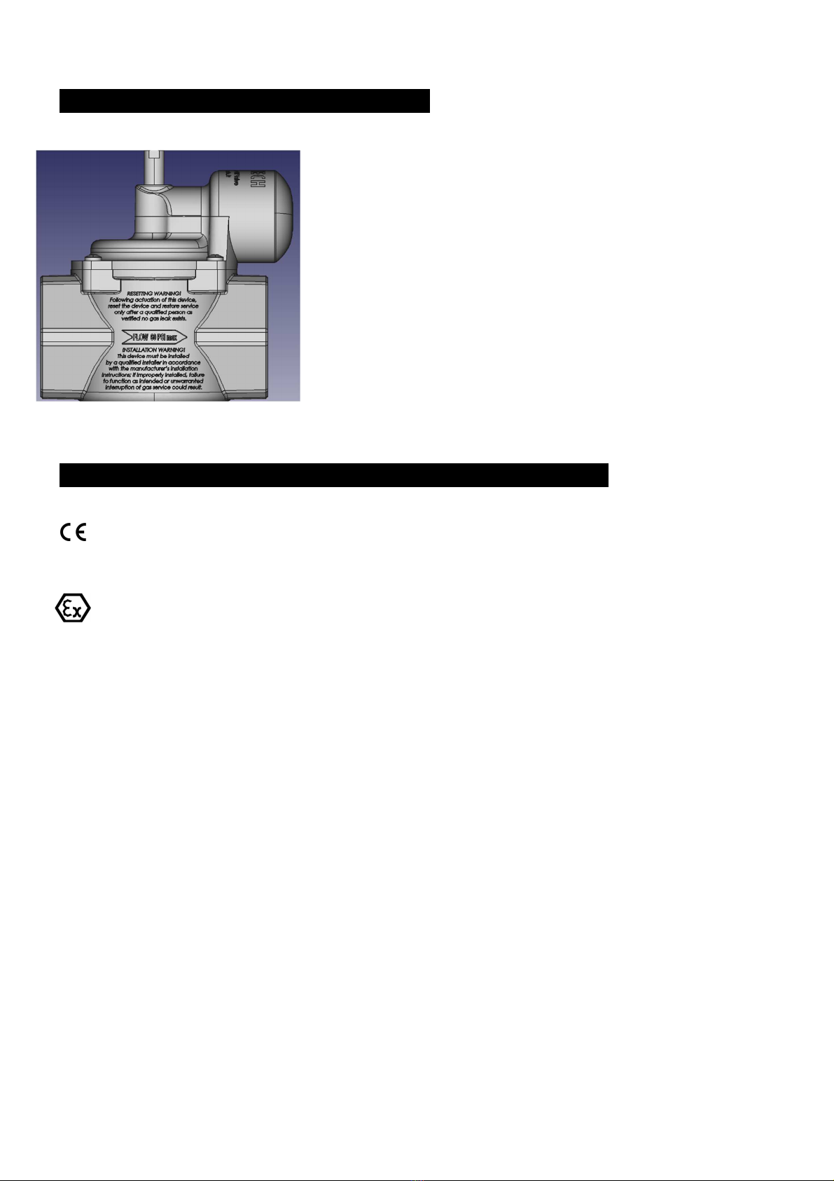
WARNINGS / INDICATIONS ON THE PRODUCT
ATTENTION! This device must be installed by a qualified technician according to the
regulations in force; if installed improperly, it could cause non-functioning such as
intentional or unjustified interruption of the gas supply service.
FLOW / ARROW = the seismic valve must be installed respecting the flow direction
indicated by the line with the arrow on the body, paying attention to the maximum
operating pressure.
Notice for recovery:
ATTENTION! Following activation of the device, it can only be reset after a qualified
technician has checked that there are no gas leaks.
LIST OF SYMBOLS USED IN THE PRODUCT AND IN THE CERTIFICATES
= compliance with applicable European Directives
0918 = Notification Body (TUV) identification code
= indicates a product compliant with installation in a hazardous area, for further Atex indications
check page 5
TS: -25°C ~ +66°C = Temperature range within which compliance and intrinsic safety is guaranteed
S.N.= erial number
DN = size connections
P. Max = Maximum working pressure
Position = Working position (that can be horizontal and vertical)
YEAR = production year
It is possible to consult the technical data of the valve in the body of the product itself,
and in the packaging label.

P a g e . 13 | 15
E AMPLE OF DECLARATION OF CONFORMITY

P a g e . 14 | 15
WARRANTY AND COMPLAINTS
-TECH / Gas Broker rl guarantees the conformity of the products supplied, guaranteeing that they correspond in
quality and type to what is established in the order confirmation and that they are free from defects that could
make them unsuitable for their intended use, on condition that correct installation has been carried out according
to the instructions in this manual and that corrosive gases are not used.
The V valve is maintenance-free and for no reason must it be disassembled by accessing the internal parts; the
assembly of the screws on the valve body is done in such a way that there is evidence of any disassembly, in
the case of attempts to disassemble the warranty automatically lapses.
-TECH makes no further warranties for this product
Validity of the guarantee: 3 years, starting from the date of purchase of the product.
The buyer is required to verify the correspondence between the products indicated in the transport document and
the products delivered and any complaints must be made by the Buyer within a short timeframe from the moment
in which the products arrive at the place of destination and in any case, under penalty forfeiture, no later than 15
days from that moment.
The warranty for defects is limited only to product defects resulting from design, material or construction defects
attributable to Gas Broker .r.l., and does not apply in the event that the Purchaser cannot prove that he has made
a correct use and installation by qualified personnel, proper storage of the products and not having modified or
repaired them without the seller's consent.
Any complaints must be made in writing and must indicate in detail the defects or non-conformities contested. Any
return must be previously authorized by Gas Broker srl. Following a regular complaint by the Buyer, made pursuant
to this article, Gas Broker s.r.l., at its choice, may:
supply free of charge, ex works, to the Buyer products of the same type and quality as those found to be defective
or not conforming to what has been agreed;
credit the Buyer a sum of money equal to the value of the products found to be defective or non-compliant.
If it is verified that the complaint is unfounded or the product is damaged and / or installed not in accordance with
the provisions of this manual, the Buyer will be required to compensate Gas Broker s.r.l. all costs incurred for the
assessment including, by way of example, the analysis of the complaint, control, testing and inspection.
The warranty starts from the date of purchase of the product; to obtain the warranty service if the product is
malfunctioning, Gas Broker srl must be notified within the warranty coverage period, presenting the relative
purchase invoice.
Limitation of Liability
The responsibility of Gas Broker s.r.l. is limited only to the value of the product supplied and according to the
warranty conditions specified above with the exclusion of any liability and claims for compensation for any damage
that may arise to people or things.
In any case, notwithstanding the provisions of articles 1578 et seq. c.c., Gas Broker s.r.l. is not liable for direct,
indirect or otherwise suffered by the buyer or third parties due to the use or non-use of the products supplied.
Under no circumstances will Gas Broker srl be liable for any incidental, special or consequential damages,
personal injury, property damage, damage due to non-use, business interruption, loss of profits or loss of
goodwill, costs associated with the replacement of the seismic valve, removal or installation costs.

P a g e . 15 | 15
This manual is subject to copyright and intellectual property laws, the terms of which must be observed and
followed. The information given in this manual could contain technical inaccuracies or typographical errors.
The information contained therein may be changed or updated without notice, just as Gas Broker srl may
make improvements and / or modifications to the products and / or manuals described at any time without
notice.
Contacts
GAS BROKER srl - S-TECH
Via Villa del Bosco 18,
35037 – Teolo (PD) – Italy
Phone: +39 0495460876
Mobile/WhatsApp: +39 3428630227
Technical assistance: tecnico@s-tech.it
www.s-tech.it
it is a trade mark of Gas Broker srl
The following manual is subject to the intellectual property of Gas Broker srl and cannot be reproduced or copied.
Rev 18 07 2022
S-TECH / Gas Broker Srl reserves the right to make changes and updates to these
instruction manuals without prior notice.
Table of contents
Popular Control Unit manuals by other brands

Acrel
Acrel ASL100 Series instructions

Pilz
Pilz mc1p coated operating instructions

Carel
Carel pGD Touch Series quick start guide

Staubli
Staubli CombiTac direqt Assembly instructions

Leroy-Somer
Leroy-Somer R 725A Connection and Adjustments

VAT
VAT 61228-KAGG-0002 Installation, operating, & maintenance instructions

Speck
Speck UL50/1000Dr operating instructions

ELCOS
ELCOS CAM-335 user manual

CommScope
CommScope CMOD installation instructions

Victaulic
Victaulic FireLock 758-LPA Series Installation, Maintenance, & Testing Manual

KLINGER
KLINGER INTEC K210-FS Assembly and Repair Instructions

Nibe
Nibe SMO 20 Installer manual


