Speck UL50/1000Dr User manual

D1958 0917S
BETRIEBSANLEITUNG
OPERATING INSTRUCTIONS
UNLOADER - VENTIL UL50/1000Dr
UNLOADER VALVE
Leistungsbereich – Performance
Type Betriebsdruck
von bis Q
max. Best.-Nr. Model Operating
Pressure max. Flow Rate
max. Code No.
UL50/1000Dr
M24x1.5 AG 50 – 1000 bar 5-50 l/min 00.6671 UL50/1000Dr
M24x1.5 (M) 50 – 1000 bar 5-50 l/min 00.6671
UL50/1000Dr
M26x1.5 IG 50 – 1000 bar 5-50 l/min 00.6701 UL50/1000Dr
M26x1.5 (F) 50 – 1000 bar 5-50 l/min 00.6701
Max. Betriebsdruck 1000 bar
Mindestdurchflußmenge 5 l/min
Max. Wassertemperatur 60°C
Max. Operating Pressure 1000 bar
Min
imum Flow Rate 5 l/min
Water Temperature max. 60°C
Instandsetzung, Einstellung
Service and Adjustment
Instandsetzungs- und Einstellarbeiten dürfen nur vom Fachperso-
nal durchgeführt werden! Werkseitig wird der Verstellweg des
Handrades von null auf Max
-Betriebsdruck durch kontern der Mu
t-
ter (33) gegen das Handrad (32) eingestellt. Beide Teile sind ge-
gen Verstellung versiegelt. Für Lagerung und Transport werden
die Ventile entspannt.
Servicing and adjustment are only to be carried out by qualified
persons. The valves are detensioned for transport and storage
purposes. The operating pressure within the scope of zero to max.
pressure is set at our works via the hand wheel and secured by fix-
ing nut (33) against the hand wheel (32). Both parts are sealed
against readjustment.
Einbau in das Gerät
Assembly into the Unit
Das Ventil wird an den Anschlussstutzen (Eingang 11, Ausgang 27)
angeschlossen. Die Anschlussstutzen sind mit 135Nm in das
G
e-
häuse geschraubt. Damit die gehäuseseitige Verschraubung des
Anschlussstutzens nicht überlastet wird, muss bei der Mont
a
ge der
Schläuche an die Anschlussstutzen (11,27) an den Sechskanten
gegen gehalten werden.
Der HD-
Schlauch muss kurz hinter dem
UL
-Ven
til an einer Halterung abgefangen werden, damit er keine
zusätzliche Kraft auf den Anschlussstutzen (27) ausübt.
Aus Siche
r-
heitsgründen werden die Anschlußstutzen (11
/ 27) durch die A
n-
schlußsicherung zusätzlich vor einem Herausreißen aus dem Ge-
häuse gesic
hert(nur bei 00.6671).. Die Anschlußsicherung (41A
-
41D) muss immer am Ventil angebracht we
rden.
Bei der Montage der Bypassleitung an den Bypassventilstopfen
(13) muss ebenfalls an dem Sechskant gegen gehalten werden.
The connecting branches (inlet 11, outlet 27) are screwed into
the valve casing at 135Nm. To avoid these branches being
over tensioned on the valve casing side, the hexagons must be
counter held when fitting the respective hose to its co
nnecting
branch (11,27).
The HP hose must be fixed with a separate clamp to the base frame
downstream of the valve to avoid any additional force on the co
n-
necting branch (27).
The rupture guard (41A
-
41D) also protects connecting branches (11
and 27) against breaking off the casing (only on 00.6671) and must
alw
ays be fitted to the valve due to safety reasons.
The hexagon must be counter held when fitting the b
ypass line
to the bypass valve plug (13).
Druckeinstellung:
To Adjust Pressure
Soll das UL auf einen niedrigeren Betriebsdruck fixiert werden, ist
folgendermaßen zu verfahren:
If the UL is to be set at a low operating pressure, proceed as follows:
Bei laufender Pumpe und geöffneter Pistole (sind mehrere Pistolen
vorhanden, alle Pistolen öffnen) wird das Federpaket mit dem
Handrad (32) vorgespannt, bis
der gewünschte Betriebsdruck e
r-
reicht ist bzw. kein Wasser mehr auf der Bypassseite ausströmt.
Mutter (33) lösen, bis zur Federführung (3) schrauben. Handrad
nachdrehen und mit der Sechskantmutter (33) in der Position kon-
tern. Ist die Düsenöffnung genau auf Fördermenge und Druck der
Pumpe abgestimmt, so darf bei Erreichen des Betriebsdruckes kein
Wasser durch den Bypass abströmen.
with the pump running and the spray gun open (if more than one
gun is used, all guns must to be open), the spring pack is tensioned
by turning the hand wheel (32) until the required pressure is reached
or until no more water flows through the bypass. Screw nut (33) to
spring guide (3). Then screw down hand wheel and lock in position
with hexagon nut (33). If the nozzle hole corresponds exactly to the
flow rate and pressure of the pump, no water should run through the
bypass after full operating pressure has been reached.
Ist die Düsenöffnung zu klein, so dass bei Erreichen
des maximalen Pumpendruckes nicht die gesamte Fö
rdermeng
e
über die Düse abströmen kann, darf das Ventil keinesfalls über
den maximalen Betriebsdruck der Pumpe eingestellt werden. Der
Bypass muss dann teilgeöffnet bleiben. Es ist jedoch empfehlens-
wert, in diesem Fall geeignete Düsen ei
nzusetzen.
Das zusätzlich vorgeschriebene Sicherheitsventil zwischen Pumpe
und UL
-Ventil muss immer höher eingestellt sein als das UL-
Ventil.
Auch die Druckspitzen der Pumpe dürfen das Sicherheitsventil
nicht auslösen. Ein Auslösen des Sicherheitsventiles führt zu
Schaltstörungen des UL-Ventiles.
If, after reaching max. pump pressure, the com-
plete flow cannot go through the nozzle because the hole is too
small, on no account is the unloader valve to be adjusted above
the max. pump operating pressure. The bypass must then r
e-
main pa
rtially open. In such cases it is always best to use cor-
rectly s
ized nozzles.
The additionally required safety valve between the pump and
unloader valve must always be set higher than the unloader
valve. Pressure peaks from the pump must not active the s
af
ety
valve. Safety valve activation will cause the unloader to switch
irregularly.

D1958 0917S
Reparatur / Instandsetzung:
Fangblende demontieren! Lösen der beiden
Sechskantmuttern (Bild 1)
Repair- and Service instructions
Disassemble visor catch! Loosen the two hex nuts
(Photo 1)
(Bild 1 / Photo 1) (Bild 2 / Photo 2) (Bild 3 / Photo 3)
Innensechskantschrauben (31) lösen (Bild2), Flansch (3A),
Federführung (3) mit Handrad (32) und Gewindestift (34),
sowie Lagerteile (36) mit Tellerfederpaket (35) nach oben
abnehmen (Bild3 / Bild4 / Bild5).
Remove hexagon socket screws (31) (Photo 2), pull flange
(3A), spring guide (3) together with hand wheel (32) and
threaded screw (34) along with bearing parts (36) and plate
spring pack (35) up and off (Photo 3 / Photo 4 / Photo 5).
(Bild 4 / Photo 4) (Bild 5 / Photo 5) (Bild 6 / Photo 6)
Bypassgehäuse (2) mit Bypassventilkörper (21) nach oben
abheben (Bild 6). Zentrierscheibe (25) und Dichtungen aus
dem Gehäuse (1) entnehmen. Bypassventilkörper (21) aus
dem Bypassgehäuse (2) herausziehen (Bild 6). Oberfläche
in der Bohrung des Bypassgehäuses und am Bypassventil-
körper (21) auf Beschädigungen prüfen (Bild 7). Besonders
die Dichtkante in der Öffnung unten am Bypassventilkörper
(zum Kolben) muss frei von jeglichen Beschädigungen sein
(Bild 7). O-Ring (22, 24, 26) erneuern und vor dem Zusam-
menbau leicht einfetten. Zentrierscheibe (25) mit Drehrille
nach oben einlegen.
Lift bypass casing (2) together with bypass valvdy (21) up
and off (Photo 6). Take centring disc (25) and seals out of
casing (1). Pull bypass valve body (21) out of the bypass cas-
ing (2) (Photo 6). Check the bore surface in the bypass cas-
ing and on the bypass valve body (21) for damage (Photo 7).
The sealing edge on the opening of the bypass valve body
(towards the piston) must be free of all damage (Photo 7).
Replace O-rings (22, 24 26). Coat new ones lightly with
grease before fitting. Fit centring disc (25) with the groove
side facing up

D1958 0917S
(Bild 7 / Photo 7) (Bild 8 / Photo 8) (Bild 9 / Photo 9)
Gehäuse im Schraubstock drehen.
Innensechskantschrauben (5) lösen (Bild 8), Deckel (4) ab-
nehmen (Bild 9) und Zentrierhülse (4A) aus dem Gehäuse
ziehen (Bild 10 / 11). O-Ring (22) und Stützring(23) (Bild
11a) überprüfen und ggf. erneuern.
Kolben (10) aus dem Gehäuse herausziehen (Bild 12).
Oberflächen am Kolben, hier besonders im Bereich der
Dichtungslauffläche und an der oberen Dichtfläche (zum
Bypassventilkörper) (Bild 13), als auch im Gehäuse prüfen
und Ablagerungen vorsichtig entfernen (abgenutztes
Schmirgelleinen!). Bohrungen im Kolben und im Gehäuse
auf freien Durchgang überprüfen. O-Ringe (6,8) und Stütz-
ringe (7,9) erneuern und vor Zusammenbau leicht fetten
Turn casing.
Remove hexagon socket screws (5) (Photo 8), take off cover
(4) (Photo 9) and pull centring sleeve (4A) out of the casing
(Photo 10 / 11). Examine O-rings (22) and support ring (23)
and replace where necessary (Photo 11a). Take piston (10)
out of the casing (Photo 12)
. Examine piston surface,
particularly the seal contact areas and the top sealing area
(towards the bypass valve body) (Photo 13). Also examine
surfaces in the casing and carefully remove any deposits (old
emery cloth grain). Check that bores in the piston and casing
are clean and unobstructed. Replace O-rings (6, 8) and
support rings (7, 9). Coat new ones lightly with grease before
fitting.
(Bild 10 / Photo 10) (Bild 11 / Photo 11) (Bild 11a / Photo 11a) (Bild 12 / Photo 12) (Bild 13 / Photo 13)
Die Drossel (18, 17) im Anschlussstutzen (27)
bzw. im Bypassventilstopfen (13) ist durch die Feder (20,
15) vorgespannt und kann plötzlich herausspringen. Verlet-
zungsgefahr (Bild 16).
Anschlussstutzen (27) herausschrauben (Bild 14), Drossel
(18) mit einem kleinen Schraubendreher durch Hebeln in
den seitlichen Schlitzen des Anschlussstutzen (27) heraus-
lösen (Bild 16). Oberflächen von Ventilkegel (19), Drossel
(18) prüfen, ggf. ersetzen (Bild 17). Teile wieder in An-
schlussstutzen einpressen (Bild 18). Dichtkantenring (22A)
mit Silikonfett in der Nut von (18) fixieren (Bild 19). Neuen
O-Ring (28) leicht fetten (Bild 19). Anschlussstutzen (27)
mit 135Nm anziehen (Bild 20 / 21).
The restrictors (18, 17) in the connecting branch
(27) and bypass valve plug (13) are tensioned by springs (20,
15) and can suddenly jump out. Beware of this danger (Photo
16).
Screw out connecting branch (27) (Photo 14). Using a screw-
driver, lever out restrictor (18) over the side slits in the connect-
ing branch (27) (Photo 16). Examine surfaces of valve cone
(19) and restrictor (18) and replace if necessary (Photo 17).
Press the parts into the connecting branch (Photo 18). Position
the seal edge ring (22A) in groove (18) using silicon grease
(Photo 19). Grease the new O-ring (28) lightly(Photo 19).
Tighten connecting branch (27) at 135 Nm (Photo 20 /21).
(Bild 14 / Photo14) (Bild 15 / Photo 15) (Bild 16 / Photo 16) (Bild 17 / Photo 17)
D1958 0917S
(Bild 18 / Photo 18) (Bild 19 / Photo 19) (Bild 20 / Photo 20) (Bild 21 / Photo 21)
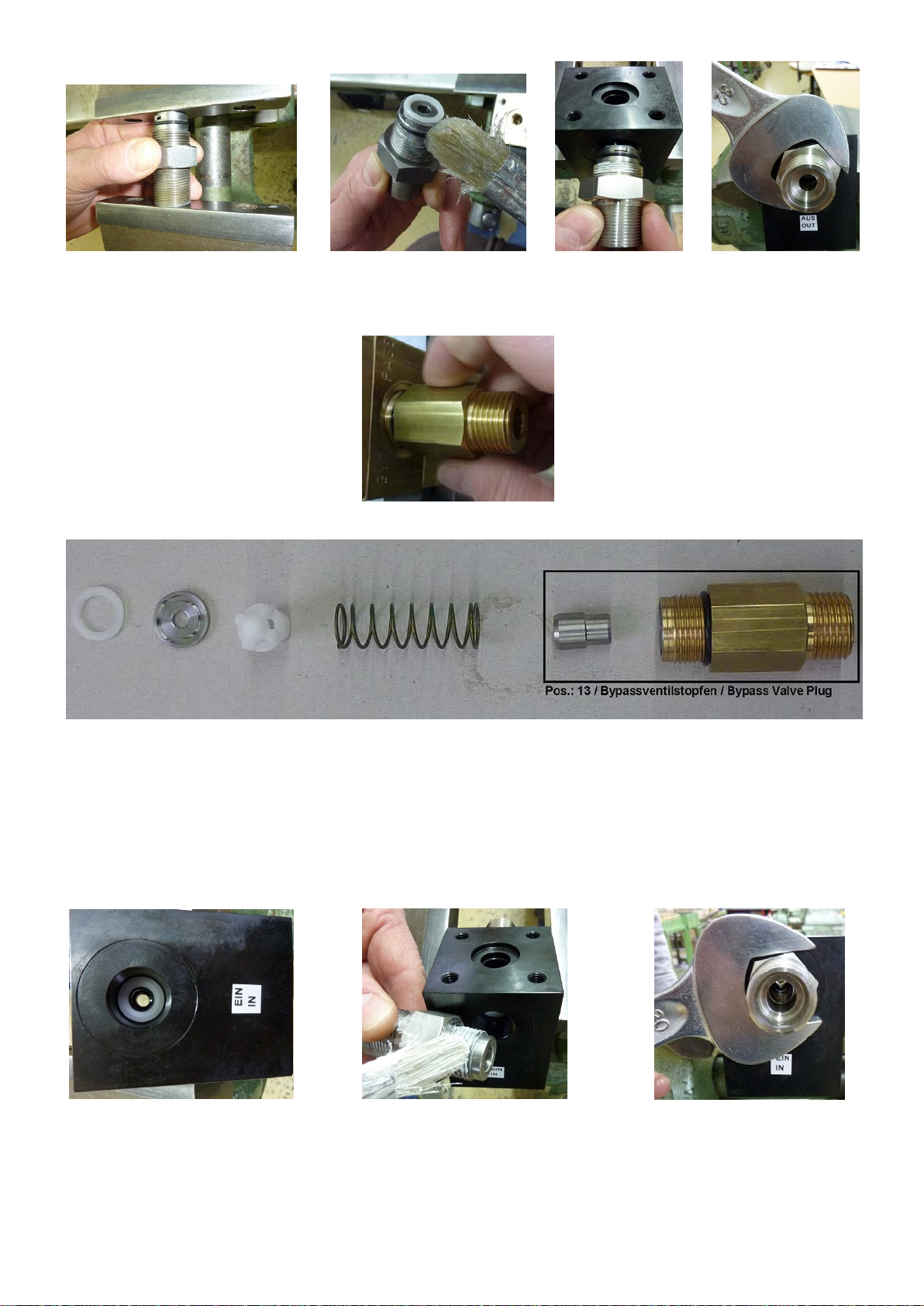
Bypassventilstopfen (13) herausschrauben (Bild 22). Ober-
flächen überprüfen (Bild 24). Restliche Vorgehensweise wie
bei (27).
Screw out bypass valve plug (13) (Photo 22). Examine sur-
faces (Photo 24). Continue as described for (27).
(Bild 22 / Photo 22)
(Bild 24 / Photo 24)
Zusammenbau:
Assembly:
Dichtkantenring (22A) mit Silikonfett in der Nut von (18)
fixieren (Bild 19). Neuen O-Ring (28) leicht fetten (Bild 19).
Anschlussstutzen (27) mit 135Nm anziehen (Bild 20 / 21).
Position the seal edge ring (22A) in groove (18) using silicon
grease (Photo 19). Grease the new O-ring (28) lightly (Photo
19). Tighten connecting branch (27) at 135 Nm (Photo 20
/21).
(Bild 25 / Photo 25) (Bild 26 / Photo 26) (Bild 27 / Photo 27)
Dichtkantenring (12) ins Gehäuse (1) (Bild 25) einlegen.
Anschlussstopfen Eingang (11) mit Silikonfett einschmieren
(Bild 26) und einschrauben und festziehen (Bild 27).
Border seal ring (12) into the casing (1) (Photo 25). Input port
plugs (11) lubricate with silicone grease (Photo 26) and screw
and tighten (Photo 27).

D1958 0917S
(Bild 28 / Photo 28) (Bild 29 / Photo 29) (Bild 30 / Photo 30) (Bild 31 / Photo 31)
Kolbenstange (10) mit Teflon-Montagefett einfetten (Bild 28)
und in das Gehäuse
(1) vorsichtig einführen und auf
Leichtgängigkeit achten (Bild 29). Stützring (9) und O-Ring
(8) in Zentrierhülse (4A) einlegen und mit Silikonfett
einfetten (Bild 30). Sowie äußerer Stützring (7) und O-Ring
(8) montieren und mit Silikonfett einfetten. Kompletter
Stützring vorsichtig auf Kolbenstange auffädeln und in die
Bohrung des Gehäuses (1) eindrücken (Bild31).
Lubricate the piston rod (10) with teflon grease (Photo 28)
and fit it into the casing (1) carefully (Photo 29) and check if it
works smoothly. Assembly Support ring (9) and O-ring (8) in
the centering sleeve (4A) and lubricate with silicone grease
(Photo 30). The outer support ring (7) and O-ring (8) need
also silicone grease. Put the support ring carefully on the
piston rod and push it into the bore of the housing (1) (Photo
31).
(Bild 32 / Photo 32) (Bild 33 / Photo 33) (Bild 34 / Photo 34) (Bild 35 / Photo 35)
Deckel(4) auf das Gehäuse (1) und der Zentrierhülse (4A)
setzen (Bild 32) und ausrichten (Bild 33). Schrauben (5) mit
Montagfett einfetten (Bild 34) und montieren (Bild 35).
Put the cover (4) on the housing (1) and the sleeve (4A)
(Photo 32/33) and align the cover(4) (Photo 33). Screws (5)
lubricate with grease (Photo 34) and assemble the screws
(Photo 35).
(Bild 36 / Photo 36) (Bild 37 / Photo 37) (Bild 38 / Photo 38) (Bild 39 / Photo 39)
Das bis dahin montierte Gehäuse (1) wird umgedreht, damit
die offene Seite nach oben zeigt (Bild 36). Der O-Ring (22)
und der Stützring (23) wird nun in die Bohrung eingelegt
(Bild 37) und mit Silikonfett gefettet (Bild 38). Die
Zentrierscheibe(25) wird in das Gehäuse(1) eingelegt (Bild
39).
The mounted housing (1) must be inverted so that the open
side is facing up (Photo 36). The O-ring (22) and the support
ring (23) inserted into the bore (Photo 37) and lubricated with
silicone grease (Photo 38). The centering disc (25) is inserted
into the housing (1) (Photo 39).

D1958 0917S
(Bild 40 / Photo 40) (Bild 41 / Photo 41) (Bild 42 / Photo 42) (Bild 43 / Photo 43)
Bypassventilkörper (21) und O-Ring
(24) mit Silikonfett
einfetten (Bild 40/41). Bypassventilkörper
(21) ins die
Zentrierscheibe (25) montieren (Bild 41). Bypassgehäuse
(2) auf Gehäuse (1) aufsetzen und ausrichten (Bild 42).
Lagerteil (36) mit Tef
lonfett fetten und auf
Bypassventilkörper (21) aufsetzten (Bild 43).
Bypass Valve Body (21) and O-Ring
(24) lubricate with
silicone grease (Photo 40/41). Put the Bypass Casing (2) on
the casing (1) and align them (Photo 42). The Bearing Part
(36) must be lubricate with Teflon grease and put the bearing
part (36) on the Bypass Valve Body (21) (Photo 43).
(Bild 44 / Photo 44) (Bild 45 / Photo 45) (Bild 46 / Photo 46)
Tellerfedernpaket (35) mit Lagerteil
(36) auf unteres
Lagerteil (36) (Bild 43/44) aufsetzen. Federführung (3) mit
Gewindestift (34), Handrad (32) und Flansch (3A) über die
Tellerfedern auf das Gehäuse aufsetzen (Bild 45) und
miteinander verschrauben (Bild 46
). Schrauben sollten
immer diagonal angezogen werden.
Plate spring assembly (35) with the bearing part (36) on the
lower bearing part (36) (Photo 43/44) onto. Put the spring
guide (3) with threaded stud (34), hand wheel (32) and flange
(3A) of the disc springs on the housing (Photo 45) and screw
together (Photo 46). Screws should be tightened always
diagonally.
(Bild 47 / Photo 47) (Bild 48 / Photo 48)
Zum Schluß muß die Anschlußsicherung (41) (Bild 47)
montiert werden (Bild 48).
Finally, the rupture guard (41) (Photo 47) must be installed
(Photo 48).
SPECK - KOLBENPUMPENFABRIK
Otto Speck GmbH & Co. KG · Postfach 1240 · D-82523 Geretsried
Tel. (08171) 62930 · Telefax (08171) 629399
Table of contents
Other Speck Control Unit manuals


