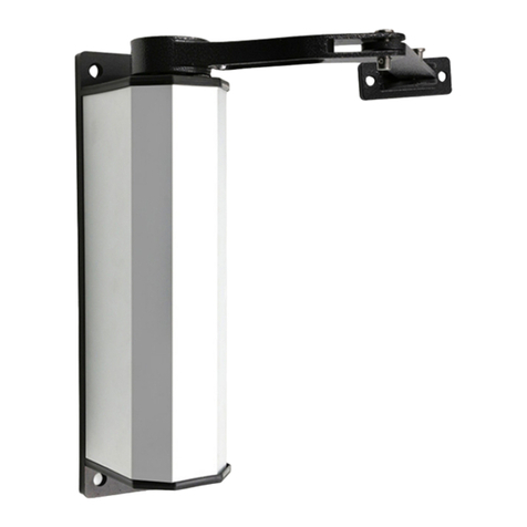
S4A ED100 User manual

ED100
Intelligent Automatic Flat Door system

Catalog
1. Technical parameter
2. Description of accessories
3. Mechanical installation
3.1 Installation example
3.2 Baseboard installation
3.3 Arm installation
3.4 Push arm installation
3.5 Driver system installation
3.6 Hood installation
3.7 Connection of drive system and pull arm
3.8 Driver system and push arm connection
4. Electrical connection
5. Parameter adjustment
6. Quality Assurance Certificate / Qualification Certificate
1
2
3 - 9
3
4 - 5
6
7 - 8
9
9
10
10
11 - 12
13 - 14
15

Technical parameter
Power supply: 200V~240V
Opening time: 3~7s/90°
Opening and holding time: 1~30s
Temperature: -20°C~55°C
Protection level: IP12D
Product weight: 6.5Kg
Product volume: 515x95x90mm
mm = Door width
kg = Door weight
Optimum scope
Limit range
1200
1000
2000
mm
80 100 140 200
kg

Description of accessories
Power cord hole Sensor equilibrium hole
Floor Hood
Power Connection Seat Motor Microcomputer Controller
Driving Device Output shaft Transformer
Pull arm (and push arm choose one) Push arm (choose one from pull arm)

Mechanical installation
3.1 Installation example
Pull- arm mounting: Suitable for door wing opening inward (drive system inside)
Push Arm Installation: Suitable for door wing opening outward (drive system inside)

Mechanical installation
3.2 Baseboard installation
Pull-arm mounting
Power Supply Line Equivalent Entry
φ20Sensor Line Equivalent Entry
Power Supply Line Equivalent Entry
The floor is fastened to the door
frame with eight countersunk wood
screws according to the size shown
(for steel structure, M6*15 inner
hexagonal countersunk head bolts) The floor is fastened to the door
frame with eight countersunk wood
screws according to the size shown
(for steel structure, M6*15 inner
hexagonal countersunk head bolts)
Installation on the right side of automatic door
Left Installation of Automatic Door

Mechanical installation
3.2 Baseboard installation
Push Arm Installation
Power Supply Line Equivalent Entry
φ20Sensor Line Equivalent Entry
Power Supply Line Equivalent Entry
The floor is fastened to the door
frame with eight countersunk wood
screws according to the size shown
(for steel structure, M6*15 inner
hexagonal countersunk head bolts)
The floor is fastened to the door
frame with eight countersunk wood
screws according to the size shown
(for steel structure, M6*15 inner
hexagonal countersunk head bolts)
Installation on the right side of automatic door
Left Installation of Automatic Door

3.3 Pull-arm mounting
The fixed seat of the pull
arm is fastened to the door
wing as shown.
Move the limit block to
adjust the opening angle
(the left time limit block is
on the left side)
Installation on the right side of automatic door
Mechanical installation

3.4 Push Arm Installation
The push arm fixing seat is fastened
to the door wing with two round head
wood screws according to the size shown
(for steel doors, M6*15 cross head screw is used).
According to the different depth L of the door
frame, the length of the push arm can be
adjusted by loosening three clamping bolts,
so that the angle between the push arm and
the door body is 90 degrees as shown in the figure.
Installation on the right
side of automatic door
Mechanical installation

Mechanical installation
3.4 Push Arm Installation
Limited block
Adjust limit block to graphic position in U-shaped hole

Mechanical installation
3.5 Driver system installation
Install the drive system as shown in
the illustration on the installed base
plate,with eight hexagon socket heads
screwed
Hood installation
How the hood is opened

Mechanical installation
3.7 Drive system and pull arm connection
3.8 Drive system and push arm connection
Drive shaft extension

Electrical connections
Power cord connection
Motor, transformer connection
Insurance tube 3A
External power cord 220V
Transformer 18V
Motor eight core wire
Controller
Controller
When the factory is shipped, the transformer two- core cable,
the motor eight-core cable and the controller are connected.
Entrance guard+power supply
Lock the door every time
Remote control lock Entrance guard
Electric lock +
Emergency power supply +
COM
Double door interlock (in)
COM
Double door interlock (out)
Electric lock +
Emergency power supply +
COM
+12V
0
COM
Open the door for collision/ start
Crashproof when closing the door
Entrance guard signal
Entrance guard power supply +
Entrance guard power supply -
Entrance guard signal
Electric lock +
Emergency power supply +
COM
Double door interlock (in)
COM
Double door interlock (out)
Double door synchronization (in)
COM
Double door synchronization (out)
Remote learning button
Opening speed
Door opening angle
Closing speed
Closing buffer angle
Hold open time
Reserved function
K1 Opening direction selection
K2 Master driven door selection
K3 Choose PUSH arm or PULL arm
K4 Tightness selection
Sensor power supply
Sensor power supply
Sensor signal
Sensor signal
+12V
0V
COM
Entrance guard signal
Open. the door for
collision/ start
Crashproof when
closing the door

Electrical connections
Double door synchronization
Double door synchronization (in)
COM
Double door synchronization (out)
Double door synchronization (in)
COM
Double door synchronization (out)
door A controller door B controller
In the double - opening door, the first opening and the second closing are set as the active ones, and the rear opening
is first set as the driven door, the active door K2 is set, and the driven door K2 is placed.
Double door interlock
Double door interlock (in)
COM
Double door interlock (out)
Double door interlock (in)
COM
Double door interlock (out)
door A controller door B controller
Sensor, access control and active door controller connection
Note: When two doors share one sensor or the same source, the double door may open normally. At this point, change the
two signal lines of the sensor on one of the controllers to restore normal operation.

Parameter adjustment
1. Remote learning button
2. Opening speed
3. Buffer angle of opening door
4. Closing speed
5. Buffer angle of closing door
6. Hold open time
7. Reserved function key
Clockwise speed is getting faster
Increased clockwise angle
Clockwise speed is getting faster
Increased clockwise angle
Time is longer in clockwise direction
About 21 seconds in 3/4 position
About 7 seconds at 1/4 position About 14 seconds in 1/2 position
Switch setting (K) : After setting, power off, restart is effective
K1: When the power is turned on, in the initial state, the door moves to the correct position in the direction of closing
the door, and if it moves in the direction of opening the door, the switch position is changed.
K2: When the double door is synchronized, the active door is placed and the driven door is placed (on)
K3: Choose PUSH arm or PULL arm
K4: The door is opened and the forbidden force is placed (on)
Electric lock +
Emergency power supply +
COM
Double door interlock (in)
COM
Double door interlock (out)
Double door synchronization (in)
COM
Double door synchronization (out)
Remote learning button
Opening speed
Door opening angle
Closing speed
Closing buffer angle
Hold open time
Reserved function
K1 Opening direction selection
K2 Master driven door selection
K3 Choose PUSH arm or PULL arm
K4 Tightness selection
Sensor power supply
Sensor power supply
Sensor signal
Sensor signal
+12V
0V
COM
Entrance guard signal
Open. the door for
collision/ start
Crashproof when
closing the door

Parameter adjustment
remote control
Remote learning button
Controller and controller pair code description
Normally closed
automatic
Normally open
Point move
1. Empty: Press and hold the. Remote Learning Key" button to
know that you can't hear the buzzer sound and release the button.
2. Pair code: Press the“Remote Learning Key" button and the
buzzer will sound. At this time,press any button on the remote
control, and the buzzer will beep three times, indicating that the
code is successful. The buzzer will beep when using the remote
control
3. Note: When using the remote control, the buzzer will beep twice,
indicating that the remote control and the controller are not
successfully coded. Please repeat item 2.
Press the "inching button" button, the door switch once
Electric lock +
Emergency power supply +
COM
Double door interlock (in)
COM
Double door interlock (out)
Double door synchronization (in)
COM
Double door synchronization (out)
Remote learning button
Opening speed
Door opening angle
Closing speed
Closing buffer angle
Hold open time
Reserved function
K1 Opening direction selection
K2 Master driven door selection
K3 Choose PUSH arm or PULL arm
K4 Tightness selection
Sensor power supply
Sensor power supply
Sensor signal
Sensor signal
+12V
0V
COM
Entrance guard signal
Open. the door for
collision/ start
Crashproof when
closing the door

Product Quality Assurance / Certificate
1. Under normal conditions of use, due to defects in the manufacture of the product
itself, free after- sales service can be obtained during the quality assurance period.
2. if there is a problem, please contact our company.
3. In the following cases, after- sales service is provided in the form of paid
maintenance even if the product is in the quality assurance period.
Malfunctions caused by inadvertent or unsuitable installation, repair,
and modification by the user; failures caused by the user not following
the items specified in the instruction manual
4. Please show the quality guarantee and purchase invoice
when maintenance is required.
5. Since the company does not reissue the quality guarantee,
one machine and one card, please keep it in a safe place.
Certificate
Product name
modell
Manufacturing model
inspector
Manufacturing date
Intelligent Automatic Door System
Product name Int
modell
SER.NO
Purchase date
Guarantee period
User address
username
Guarantee period
One year
telephone number
year month date
Intelligens automatikus ajtórendszer
Note: 1. The construction shop should provide customers with one -year warranty
and after-sales service, that is, the construction shop should be stamped. :
2. The wearing parts. are not covered by the warranty
Consumer consultation
China Branch
year month date year month date
Table of contents
Other S4A Door Opening System manuals
Popular Door Opening System manuals by other brands

B&D
B&D Auto-Lock Kit installation instructions

Command access
Command access SLP-UL-M-KIT installation instructions

Assa Abloy
Assa Abloy SW200 Installation and service manual

Bohle
Bohle Santos instruction manual

Dorma
Dorma COMFORTDRIVE Moveo Original Operating Instruction Manual

Dormakaba
Dormakaba G-SR EMR Series Fixing instructions