1
Chapter
ChapterChapter
Chapter 1:
1:1:
1: Product
ProductProduct
Product introduction.-----------------------------2
introduction.-----------------------------2introduction.-----------------------------2
introduction.-----------------------------2
1.1
1.11.1
1.1 Workflow-----------------------------------------------2
Workflow-----------------------------------------------2Workflow-----------------------------------------------2
Workflow-----------------------------------------------2
1.2
1.21.2
1.2 Product
ProductProduct
Product Characteristics--------------------------------
Characteristics--------------------------------Characteristics--------------------------------
Characteristics--------------------------------3
33
3
1.3
1.31.3
1.3 Main
MainMain
Main Technical
TechnicalTechnical
Technical Parameters-------------------------
Parameters-------------------------Parameters-------------------------
Parameters-------------------------3
33
3
Chapter
ChapterChapter
Chapter 2
22
2 :
::
: Installation----------------------------------
Installation----------------------------------Installation----------------------------------
Installation----------------------------------4
44
4
2.1
2.12.1
2.1 Installation
InstallationInstallation
Installation of
ofof
of mechanical
mechanicalmechanical
mechanical part
partpart
part of
ofof
of door
doordoor
door opener------
opener------opener------
opener------
2.2
2.22.2
2.2 Connection
ConnectionConnection
Connection of
ofof
of electrical
electricalelectrical
electrical part
partpart
part of
ofof
of door
doordoor
door opener
openeropener
opener ---------
------------------
---------8
88
8
Chapter
ChapterChapter
Chapter 3:
3:3:
3: Parameter
ParameterParameter
Parameter Setting
SettingSetting
Setting and
andand
and State
StateState
State Display
DisplayDisplay
Display ----------
--------------------
----------11
1111
11
3.1
3.13.1
3.1 Parameter
ParameterParameter
Parameter Setting---------------------------------------
Setting---------------------------------------Setting---------------------------------------
Setting---------------------------------------11
1111
11
3.2
3.23.2
3.2 State
StateState
State Display
DisplayDisplay
Display Description-------------------------------
Description-------------------------------Description-------------------------------
Description-------------------------------14
1414
14
3.3
3.33.3
3.3 Error
ErrorError
Error Alarm-------------------------------------------1
Alarm-------------------------------------------1Alarm-------------------------------------------1
Alarm-------------------------------------------14
44
4
Chapter
ChapterChapter
Chapter 4
44
4:
::
: Debugging-------------------------------------1
Debugging-------------------------------------1Debugging-------------------------------------1
Debugging-------------------------------------14
44
4
4.1
4.14.1
4.1 Closing
ClosingClosing
Closing Position
PositionPosition
Position Learning----------------------------1
Learning----------------------------1Learning----------------------------1
Learning----------------------------14
44
4
4.2
4.24.2
4.2 Opening
OpeningOpening
Opening Debugging-------------------------------------1
Debugging-------------------------------------1Debugging-------------------------------------1
Debugging-------------------------------------1
4.3
4.34.3
4.3 Closing
ClosingClosing
Closing Debugging-------------------------------------1
Debugging-------------------------------------1Debugging-------------------------------------1
Debugging-------------------------------------1
4.4
4.44.4
4.4 Other
OtherOther
Other Debugging---------------------------------------1
Debugging---------------------------------------1Debugging---------------------------------------1
Debugging---------------------------------------16
66
6
Chapter
ChapterChapter
Chapter
:
::
: Common
CommonCommon
Common Troubles
TroublesTroubles
Troubles and
andand
and Removal---------------------1
Removal---------------------1Removal---------------------1
Removal---------------------16
66
6
Parking
ParkingParking
Parking List-----------------------------------------------1
List-----------------------------------------------1List-----------------------------------------------1
List-----------------------------------------------18
88
8
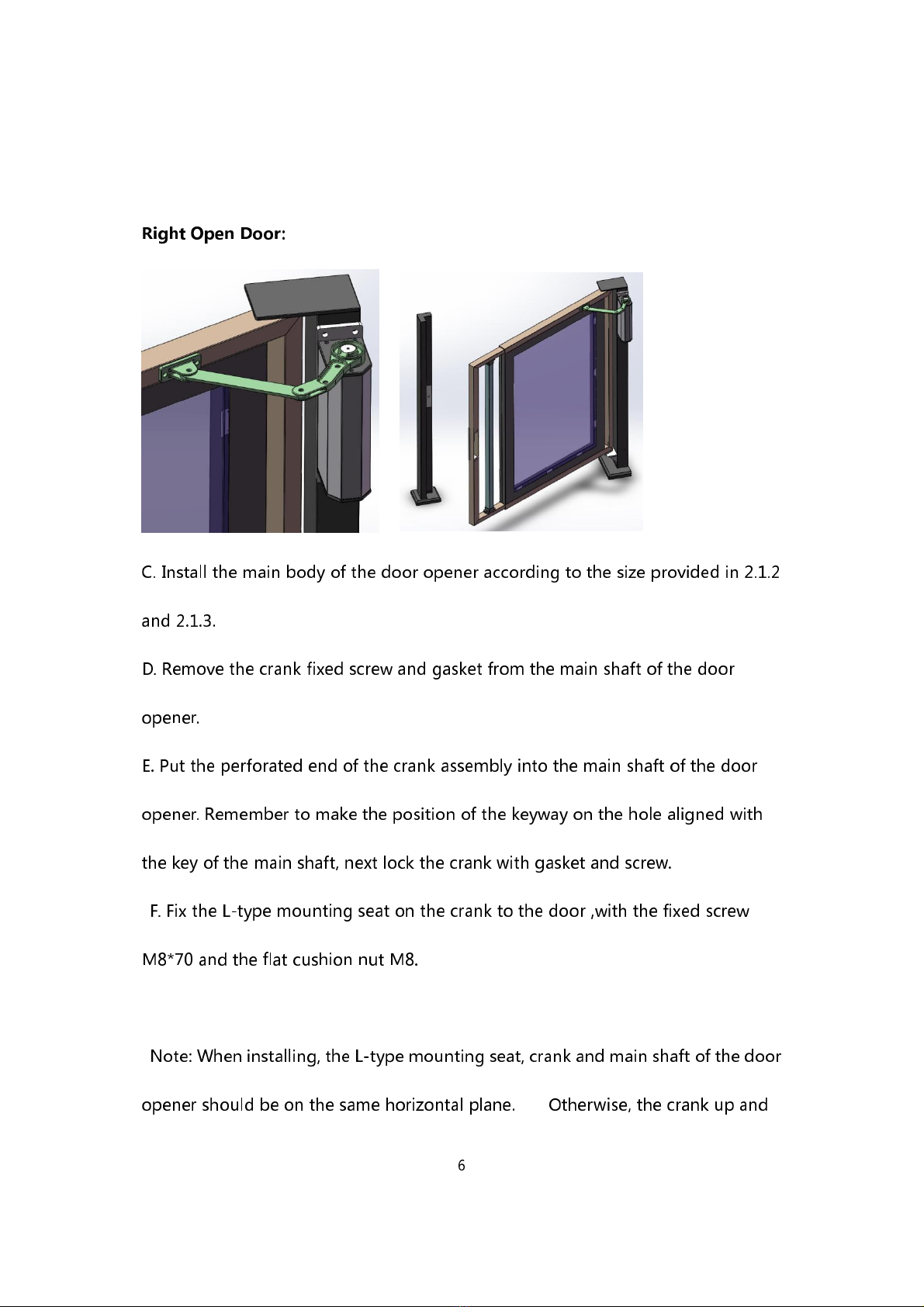
RS-140 Side-mounted
Flat Door
Opener